


How to size plumbing water pipes using fixture units. Plumbing codes use various methods to determine the size of the water piping feeding a building. One of those methods is to use Fixture Units. To figure water supply fixture units, you need to calculate the demand load that plumbing fixtures will place on a water supply system. Here are the 14 steps required to size domestic water mains and distribution piping along with how to determine fixture units and the volume of water required.
If you prefer to watch the video of this presentation than scroll to the bottom or click on this link. How to Size Plumbing Water Pipes using Fixture Units
Step #1 – Figuring Total Water Supply Fixture Units (WSFU’s)
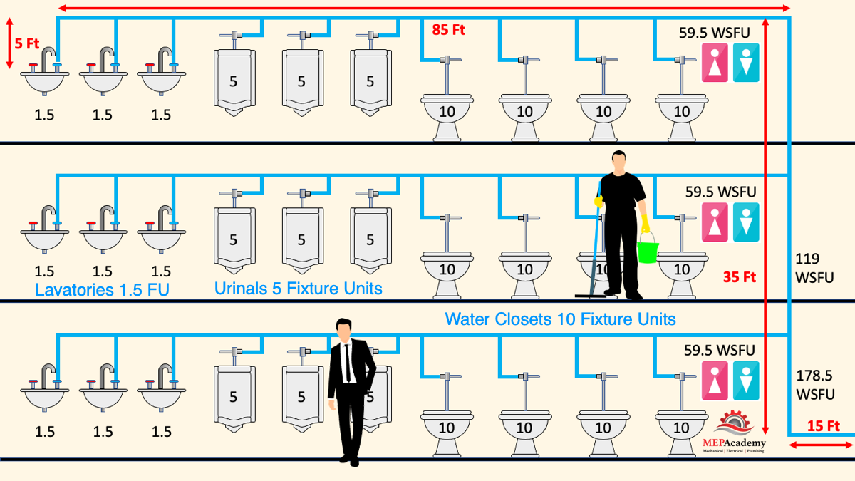
Identify the different types of plumbing fixtures that will be connected to the water supply system. Examples of common fixtures include toilets, sinks, bathtubs, showers, dishwashers, and washing machines. We’ll use a 3-story office building for our example. Here we show that each floor has four water closets, three urinals, and three lavatories.
- Determine the water supply fixture unit value of each type of fixture. Water supply fixture unit (WSFU) is a measure of the flow rate of water through a specific fixture. The WSFU of a fixture can be found in the plumbing code or by consulting a plumbing engineer. Here we show several different codes and the various tables they use for fixture unit values.
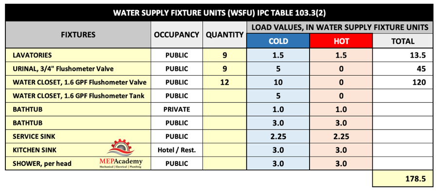
Each code will have a procedure for calculating the required flow rates based on the type and quantity of fixtures. Here we use the 2021 International Plumbing Code Table E103.3(2) for our example. The table shows that a public “Lavatory” has 1.5 fixture units, and a public “Urinal with a 3/4” flushometer valve” has 5 fixture units, and a public “Water Closet with flushometer valve” has 10 fixture units.
- Multiply the WSFU of each fixture by the number of fixtures of that type. This calculation will give you the total fixture units (WSFUs) for each fixture type.
For our example, there are three lavatories per floor, times three floors, which equals a total of 9 lavatories and based on 1.5 WSFU each, there would be a total of 13.5 fixture units for the lavatories.
There are also a total of 9 urinals with a value of 5 fixture units each. The total fixture units for all the urinals are 9 times 5 = 45. Then there are 4 water closets per floor times three floors, for a total of 12 water closets. The WSFU for a water closet with a flushometer valve is 10, which would give us 12 x 10 = 120 fixture units.
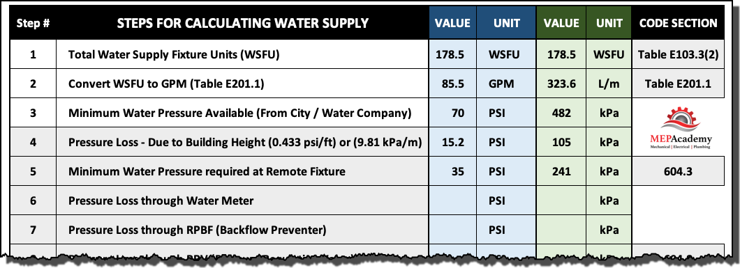
- Add up the WSFUs for all fixtures in the building or plumbing system to get the total WSFUs for that system. This will include adding up the total fixture units for each branch and riser. What we haven’t considered is any water flow demands for cooling towers, RO systems, Process Equipment, or landscaping. The plumbing engineer will need to work with the other trades to determine their needs for water. In our example we have a total of 13.5 WSFU’s for lavatories, 45 for urinals and 120 fixture units for water closets, for a total of 178.5 fixture units.
Step #2 – Determine the Water Flow (GPM) or (L/m)
Determining the water flow involves finding the total Water Supply Fixture Units in the very left column of IPC table 103.3(3), then moving along that row to the intersection of the demand column for “Supply Systems for Flushometer Valves”. The Total Fixture units are close enough to 180 so the use of this row is fine. This gives us a water flow of 85.5 GPM or 323.6 liters per minute.
Checkout these Plumbing Fixtures here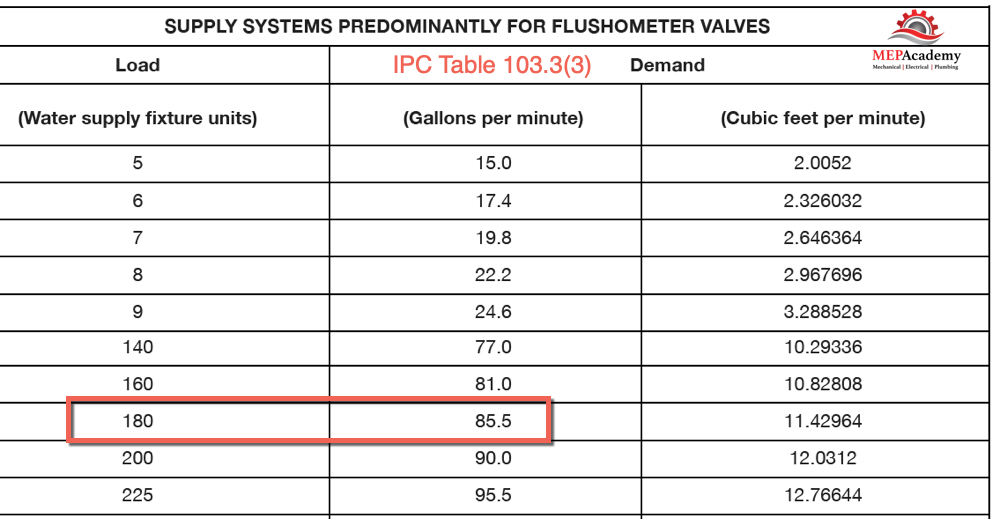
Step #3 – Obtain Minimum Daily Static Pressure Available
The available static pressure in psi or kPa at the water meter or source of water supply is provided by the City or local water authority. The minimum pressure is used in the calculations to ensure that during peak water usage season, pressure is available to operate the most demanding fixture.
Peak water usage usually occurs in summer when landscaping systems are maximized, and water-based cooling systems are utilized at their peak. It is essential that sufficient water pressure be available to overcome all the plumbing water system losses due to friction and elevation so that plumbing fixtures operate properly. For our example we’ll use 70 psi or 482 kPa.
Step #4 – Pressure Loss due to Building Height
To get the flow of water needed for the building there needs to be enough pressure left over after subtracting for all of the losses that occur due to various reasons, the first is the height of the building. Water exerts a pressure of 0.433 pounds per square inch for every 1 foot in height, or 9.81 kPa per meter.
The pressure coming from the city will be reduced by the loss occurred from this column of water sitting in the pipe risers feeding the building. In our example (see image above) the building is three stories high and has a 35 foot (10.6m) riser. To determine the loss of pressure from this column of water the following equation is used.
Riser Height in Feet (Meters) x Pressure loss per Foot (Meter)
35 Feet x 0.433 = 15.2 psi or
10.6 meters x 9.81 kPa = 105 kPa
Step #5 – Minimum Pressure required at Remote Fixture
This is to ensure that the fixture has enough pressure to operate properly. Each fixture requires different amounts of pressure to operate, so it’s important to pick the remote fixture that requires the greatest pressure to produce a flow.
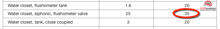
Using IPC table 604.3 the siphonic water closet with a flushometer valve needs 35 psi or 241 kPa for proper operation.
Checkout these Plumbing Fixtures hereStep #6 – Pressure loss through water meter
The friction loss or pressure loss through the water meter can be found from the manufacturer of the water meter. In our example we’ll use 6 psi or 41 kPa for the pressure loss through the meter.
Step #7 – Pressure loss through Backflow Preventer
The use of a reduced pressure backflow assembly (RPZ) is to prevent dirty water from reversing flow and contaminating the clean water supply. If required then the pressure drop needs to be included in the calculation for total pressure loss. In our example the pressure drop is 4 psi or 28 kPa.
Step #8 – Pressure loss through Pressure Regulating Valve
The IPC restricts excessive water pressure by requiring a pressure regulating valve when the pressure exceeds 80 psi (552 kPa). The reason is to reduce the incident of water hammer, reduce the excessive loss of water from pressure relief valves, and for the protection of equipment and fixtures. Since the maximum water supply in our example is less than this, there is no need for a PRV.
Step #9 – Total Pressure required for Operation
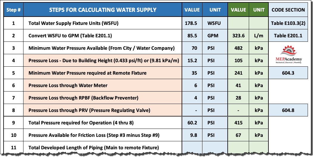
Add up all the pressure losses and the required minimum water pressure at a remote fixture with the highest requirements. Adding Steps #4 through #8 in our example equals 60.2 psi or (415 kPa). This is the total pressure required for proper operation, but not including the required pressure drop caused by the water flowing through the pipe and fittings.
Step #10 – Pressure available for Friction Loss
Subtract all the losses in Step #9 from the minimum available pressure in Step #3. If the available pressure is 70 psi or 482 kPa, then our calculation looks like this. 70 psi – 60.2 psi = 9.8 psi, or 482 kPa – 415 kPa = 67 kPa, this is the amount of pressure left over for the resistance to flow that is needed to move the required GPM or LPM to the most remote fixture.
Step #11 & 12 – Total Developed length of Piping
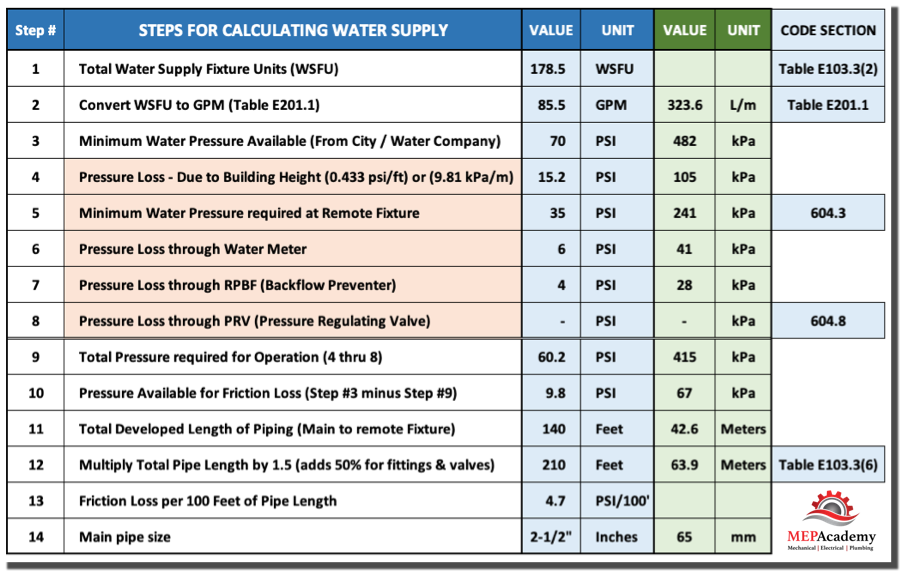
This is the developed length of the water piping between the water source and the most remote fixture times 1.5 to account for pressure loss through fittings and valves. Fittings and valves add 50% to your total length, but this could vary based on design. In the example here there is a total of 140 feet or 42.6 meters from the water source to the most remote fixture. The calculation would be 140 feet x 1.5 = 210 feet, or 42.6 meters x 1.5 = 63.9 meters of total developed length.
If you know the exact amount of fittings and valves then table E103.3(6) in the IPC could be used to determine the equivalent length for each size and type of fitting or valve.
Step #13 – Determine the Friction Loss per 100 Feet
This calculation determines the leftover pressure in the system that can be used to overcome the pressure loss due to friction in the pipes and fittings. Step #10 shows that there is 9.8 PSI or 67 kPa for friction loss.
The calculation would be (9.8 psi/210feet) x 100 = 4.7 psi/100 feet
Step #14 – Determine Size of Water Service Pipe
This is where the size of the main is determined using the information that we have put together so far.
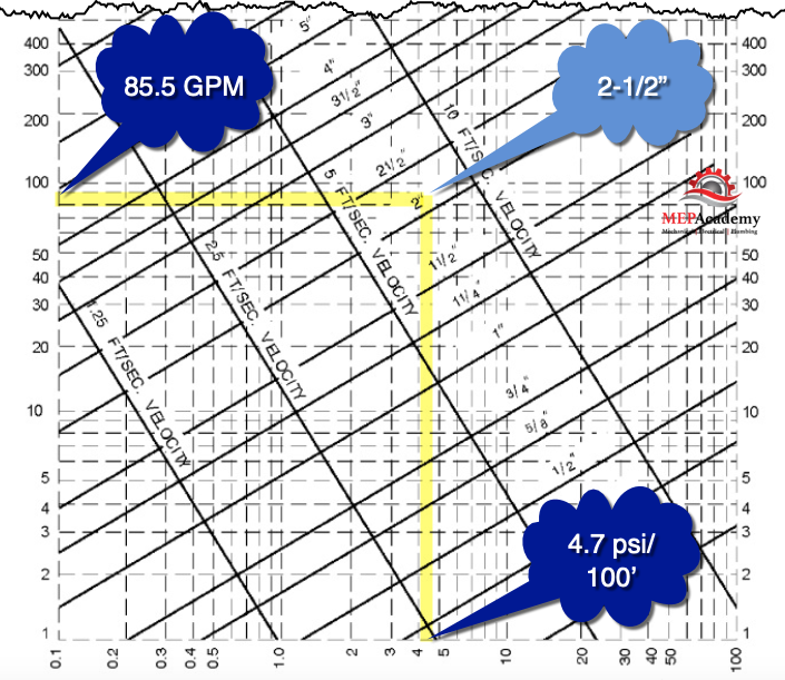
Using Figure 103.3(3) we enter the total GPM of 85.5 and our allowable pressure drop of 4.7 psi/100 feet and they intersect just above the 2” pipe line, so to be safe we’ll specify a 2-1/2” or 65mm pipe.
If we found out through our analysis that there wasn’t enough water pressure from the city to overcome all of the pressure losses and provide the minimum required pressure at the most remote plumbing fixture, then a booster pump would be considered.
