


Chapter #6 – Sheet Metal Joints
Rectangular Duct Joints
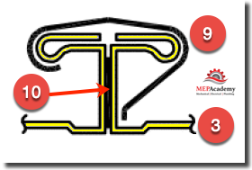
TDC – Transverse Duct Connector (SMACNA T-25A)
This traverse duct connector is fabricated from the same piece of metal as the duct (#3), and has a gasket (#10) inserted between the two joints of duct or fitting and is locked in place by a cleat (#9). Each corner will be bolted together. Watch the videos below to get a better sense of how this joint is assembled.
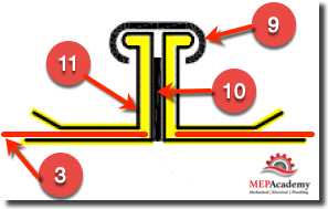
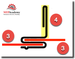
Ductmate Duct Connectors (Slip on Flange)
The Ductmate duct connector is a proprietary connector manufactured by Ductmate Industries. One of the differences between this joint and the TDC joint above is that this is a slip on flange (#11) that is not fabricated from the piece of ductwork (#3) but is attached (slipped on) and secured to the raw end of the duct or fitting. This joint also requires a gasket (#10) between the flanges and cleats (#9) to fasten the two joints together. Watch the video below to get a better understanding of this proprietary joint.
Watch the following video for a better understanding of what Ductmate offers.
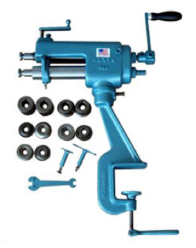
Duct Flange Rollformer Machine
This machine will make a slip-on flange to make duct joints. A fabrication shop that has this machine will be able to make their own flange instead of having to buy a proprietary flange like that manufactured by Ductmate.
The following video shows a demonstration of how the attached duct connector is assembled onto the end of a piece of ductwork.
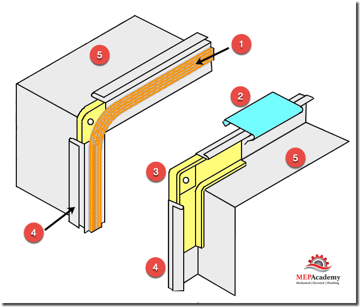
The pieces that make up the TDC or Ductmate joint is comprised of the Flange (#4) on the end of the duct (#5) or fitting, the Gasket (#1) that provides an air tight seal, the Clip or Cleat (#2) that locks the two pieces together and the corner pieces (#3) that bolt together at each corner.
To ensure a proper sealing of flanged joints the use of gaskets with bolted corner pieces will make a tight fit that reduces the chances of leakage. The gasket is a continuous length of approved material with a minimum of 16 gauge corner pieces and 3/8” bolts. The clips are used to lock together the two adjoining pieces of duct and are a minimum of 6 inches in length.
In lieu of clips, screws can be installed at 6” maximum intervals starting at a maximum of 1” inch from the corners. Clips are to be spaced at a maximum of 15” inches on center for 3” static pressure and less, and at 12” centers for 4” static pressure and above.
Watch this video on how to install Cleats/Clips.
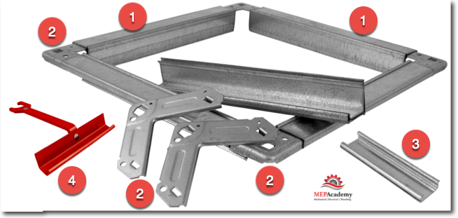
The sheet metal fabrication shop has several options when making a rectangular flanged connection. One is to use have the flange an integral piece make from the duct, or to add a proprietary flange (#1) on to the raw end of the duct such as the below from Hardcast, a Carlisle Company.
The flange (#1) has a piece for each side of the duct or fitting, and four corner pieces (#2). Cleats (#3) locks two adjoining sections of ductwork with each other or a fitting by using the Cleat Installing Tool (#4). Watch the video above to see how the cleat is attached.
TDC Corner Pieces
The corner of each section of duct will require a corner piece that allows separate sections of duct to be bolted together at their corners. The machine in the video below can do this automatically, otherwise they will be installed manually.
S & Drive Joint
Here is another method of attaching ductwork and fittings together using an Slip & Drive connector. This requires two (2) Slips and two (2) Drives for each connection.
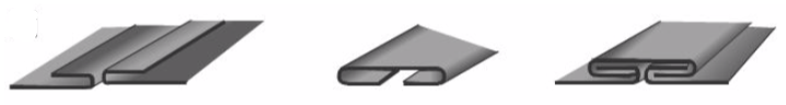
#1 in the below image is the Drive portion that gets driven at the joint.
This joint can be used at any length when exposed to 2 inch static pressure and less, and up to 36 inches in length for 3 inch static pressure and less, or 30 inch maximum length for ducts exposed to 4 inches of static pressure. Not approved for any duct static pressure over 4 inches. In the image below you have the Drive Slip (#1) that gets driven down at the joint ends (#2) of the two pieces being attached together.
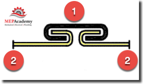
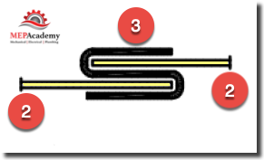
And the S-Slip (#3) shown below holds the two pieces of duct (#2) in place on the other ends of the duct, so that you end up with two Drive-Slips and two S-Slips.
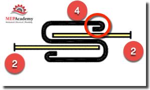
There is another version of the S-Slip called a Hemmed S-Slip because as you can see circled in red below the Hemmed S-Slip (#4) has a hem at each end.
Watch the video below to see how the Slip and Drive is attached to the end of a piece of ductwork.
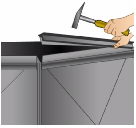
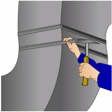
This next video shows how easy this joint really is. As you will see, the sheet metal fabrication shop worker attaches two “S” slips to the end of two sections of ducts before pushing them together, then hammering the drives on each side to lock the two pieces together.
Watch the video below to see how a manual Drive Cleat/Slip is made in the shop. There are automated drive cleat machines that would produce these faster.
Below is an automatic cleat bender that is powered by a pneumatic operator.
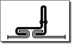
Standing Drive Slip
Standing Drive Slip is similar to S and Drive except for the additional material and strength gained by a perpendicular extension of the Drive joint. This joint can also be reinforced with a bar for additional strength. This joint can be used at any length when exposed to 2 inch static pressure and less, and up to 36 inches in length for 3 inch static pressure and less, or 30 inch maximum length for ducts exposed to 4 inches of static pressure. Not approved for any duct static pressure over 4 inches.
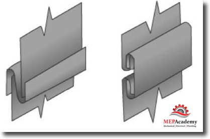
Reinforced S-Slip
This joint uses a reinforced drive slip (#1) by using a 16 gauge angle (#2) that stands 1 inch in height. The angle slips within the drive section and is fasten in place with screws. This reinforced S-Slip is good on ductwork fabricated up to a maximum of 2” static pressure. The two sections of adjoining ductwork is shown by reference in the image below as (#3).
Standing S
The Standing S joint is similar to the reinforced S-Slip, except that the standing portion (#4) is fabricated from the same metal piece as the S connector. Below you can see that the two adjoining duct sections (#3) shown in red are inserted into the “S” section.
Watch this video to see how a standing “S” lock is made.
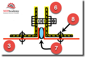
Companion Angles
This is another way to reinforce the strength of the joint by adding companion angles (#6) on each end of a duct or fitting with a gasket (#7) between them. The companion angles can be attached to the duct or fitting by rivets (#8), screws or by tack welding, while the companion angles are secured together with bolts.
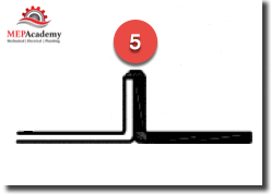
Welded Joints
Welded joints (#5) are attached by methods of welding various material types together. Most commonly welded in the HVAC industry would be Galvanized, Stainless Steel or Black Iron. This will necessitate having heavier gauge fittings and ductwork, as lighter gauges can’t handle the temperature of the welding process.
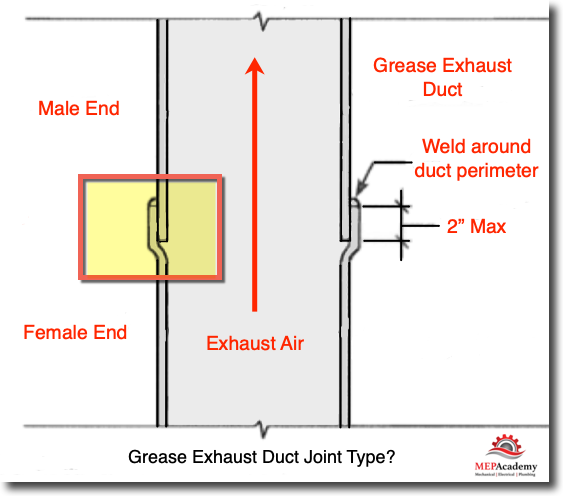
Black iron grease ductwork is a typically used for grease ducts. Two sections of ducts or a duct and a fitting are brought together and welded where their flanges meet. There are other methods of joining in welding, but the flanged joint is commonly used.
Bell Type Joint
The Bell type joint is also approved for use by the IMC (International Mechanical Code). The choice to use a particular joint is based on your sheet metal shop fabrication standards within the code approved methods. (See chapter on Grease Exhaust Systems for additional information)
Joint Length
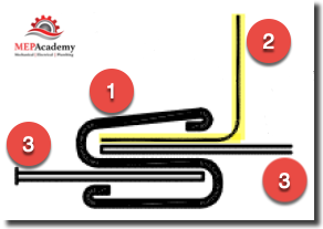
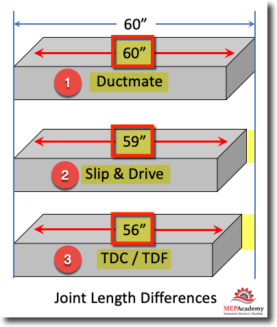
The length of the duct will vary depending on which joint you use to fabricate your ductwork. As shown in the image below, the use of Ductmate (#1) a proprietary duct joint doesn’t require roll-forming as opposed to the other two joint types.
Remember Ductmate (#1) gets slipped onto the raw end of the duct, while the TDC/TDF (#3) flange is roll-formed from the same piece of sheet metal that the duct is made from. Since Slip & Drive (#2) and the TDC/TDF Flange (#3) are made from the same material as the duct, this cause the overall length to be shorter than one that made for the use of Ductmate.
Ductmate Joint Duct Length = 60”
Slip & Drive Joint Duct Length = 59”
TDC/TDF Joint Duct Length = 56”
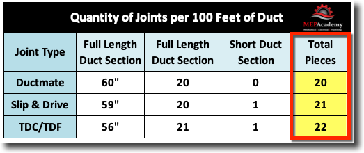
What this means is that for every 100 feet for each type of joint there will be varying amounts of duct sections as shown below. There will be a quantity of 20 Ductmate pieces, 21 sections of Slip & Drive, and 22 sections of TDC/TDF joints. This is a great difference, but we want to make sure you understand that the roll-formers use some of the end of the duct to make the joints for TDC/TDF and the Slip and Drive joints.
Round Duct Joints
Flanged Round Duct Joints
There are various methods of attaching round duct and fittings together. Here is a proprietary system by Ductmate® called “Spiralmate”. The duct can come with the flanges already attached from the fabrication shop or can be field installed. Care must be taken not to damage the flange in transit or disturb the sealant that sits in the groove of the flange. If the sealant becomes damaged then more will need to be applied to ensure a proper seal when assembled onto the end of a duct or fitting.
Here is another manufacture of a flanged round joint; the Spiral Pipe E-Z Flange System.
And with this next video you can see how the roll former turns the end of a round duct until it is 90 perpendicular to its length thereby preventing the flange from slipping off, and allowing the two mating pieces to be clamped together.
Sheet Metal Combination Rotary
Preparing sheet metal for a wired edge, turning a burr, beading, and crimping are probably the most difficult of sheet metal forming operations to perform. Crimping the ends of round duct and fittings reduces the circumferences enough to allow the end to slip into its opposing duct or fitting.
This combination rotary is used for beading and crimping which in larger fabrication shops are produced by separate pieces of equipment.
Most low pressure round fittings will either have a crimped end or be coupling sized as shown below.
Crimped Ends
Crimped ends reduce the overall diameter just slightly so that the fitting or duct can slip into the next piece.
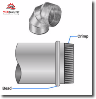
Round Couplings
Couplings slip inside the ends of two round ducts to be joined together and then sheet metal screws are fastened to hold it in place. Couplings could be required at a certain size such as connections 18” and larger. The shaded area in the image below is the coupling which has a beaded center so that each section of round ductwork slips over the coupling the same distance.
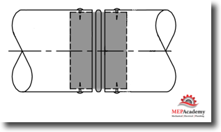
Slip/Coupling Joint
Spiral duct can slip over the end of a fitting that is made coupling size, so that crimping isn’t required. The spiral duct will slip over the fitting until it hits a beaded section preventing it from going any further. The fitting has a bead similar to the one shown at the center of the coupling above.
Welded Connections
The requirement for a welded duct connection can be found for kitchen grease exhaust systems or some industrial processes and laboratory exhaust systems. Some of the more commonly welded duct materials are galvanized steel, stainless steel and black iron. Joints are often butt welded or flanged.
Often welded kitchen exhaust systems will use stainless steel where exposed to view and black iron for the hidden duct to the grease exhaust fan. Grease exhaust ducts need cleanout doors every so often as required by code for access for cleaning. (See chapter on Grease Exhaust Systems)
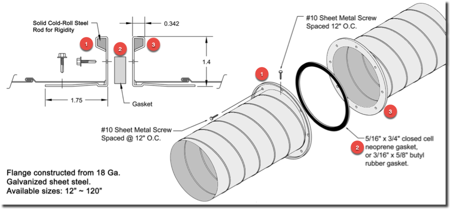
DuraFlange This is a proprietary system that uses light weight flanges that are inserted into the ends of ducts and fittings in order to join two pieces together with a neoprene or butyl gasket between them. Screws are then placed every 6 inches around the perimeter to fasten the DuraFlange to the end of the duct or fitting. This is a three piece joint, with two flanges (#1 & #3) and a gasket (#2).
Watch the video below to see how this flange works.
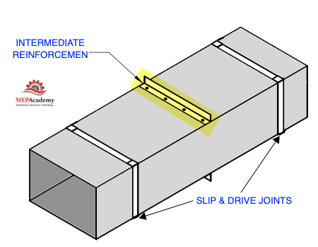
Rectangular Duct reinforcement
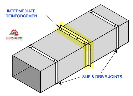
Intermediate reinforcement goes between the joints to strengthen the section of duct of fitting. The construction standards, like those established by SMACNA will dictate where and when reinforcement is required. The reinforcement could be top and bottom or on all four sides.
Also, reinforcement can be around all four sides as shown below.
Tie Rods
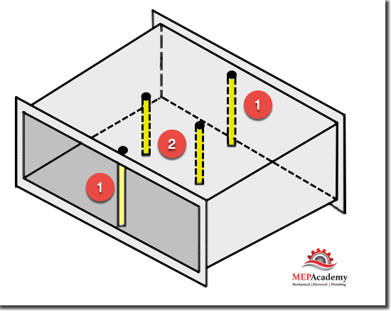
Another method of reinforcing ductwork and fittings is with the use of Tie-Rods. Reinforcement can be at the joint (JTR) or mid-way (MPT) between the joints. You can see by looking at the image below that you can have Joint Tie Rods (#1) or Mid Panel Tie Rods (#2) for additional strengthening of the duct section. The Tie-Rods are shown in yellow, with one at each end (#1) of the duct section and two mid-way (#2) between the joint ends.
EMT or solid rods are used for Tie-rods. Steel rods in sizes 1/4” & 5/16” are used or 1/2” to 1-1/4” EMT based on static pressure and distance to Mid Panel Tie Rod from joint. If the steel rod exceeds 3 feet in length, then a 3/8” steel rod must be used for added stability and strength.
Mid Panel Tie Rods
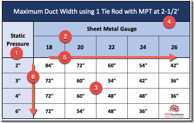
The Static Press (#1), Sheet Metal Gauge (#2) and Mid Panel Tie Rod Distance (#4) will effect the Maximum Duct Width (#3) that can use a single toe rod for reinforcement when using a Mid Panel Tie Rod distance of 2-1/2’ (#4). As the table shows with the Red Arrow (#5) as the gauge of the duct gets thinner the maximum duct width (#3) decreases, and as the Static Pressure (#1) increases, the Maximum Duct Width (#3) decreases as shown by the red arrow (#6) although not as dramatically as with the reduction in sheet thickness.
Relationship Between Width, Gauge and Reinforcement
Duct Width (#1), Thickness (gauge)(#2), Reinforcement Spacing (#3) and Reinforcement size (#4) all relate to each other and changing one usually affects the others. When you increase the Duct Width (#1) this can increase the Sheet Thickness (#2), Reinforcement Spacing (#3) & Reinforcement Sizing (#4). Likewise when you change anyone of the other items it can have an inverse relationship to the others, such as if you increase the reinforcement spacing (#3) you might be able to reduce the Duct Thickness (#2).
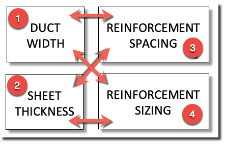
Just remember that these factors are all related. Your Sheet Metal Fabricator will usually have a set of Duct Construction Standards that they use in most situation and only make adjustments in special situations.
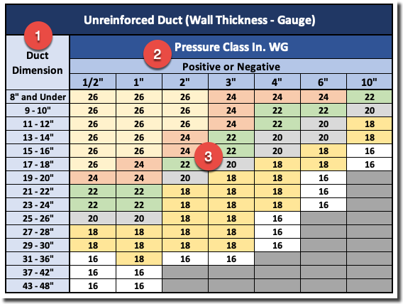
Unreinforced Ductwork
Ductwork can be built without any additional reinforcement if it remains within SMACNA’s Table 2-47 “Unreinforced Duct (Wall Thickness)”. As can be seen in the image below, as the pressure class increases (#2), so does the thickness or gauge (#3) of the duct. The same applies to the dimension of the duct, so that as the duct gets larger, the thickness of the metal increases. In summary, if the pressure or the duct dimension increases, then the thickness of the material will also increase according to the below chart.
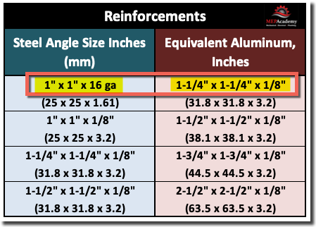
Aluminum and Reinforcement
Aluminum doesn’t have the same strength and rigidity as Galvanized steel for the same gauge or thickness. Any construction using aluminum would require an increase in the thickness of the metal and reinforcement in order to match the equivalent in strength and rigidity of that of galvanized steel. For example a 1” x 1” x 16ga Steel Angle would require a 1-1/4” x 1-1/4” x 1/8” aluminum angle to be similar in strength and rigidity (see reinforcement table below). Aluminum is 6061-T Strength.
Round Duct Reinforcement
Just like rectangular duct, round duct will require reinforcement under certain conditions. As can be seen in SMACNA Table 3-10 below, the requirements for stiffeners is based on duct size (#1) and stiffener spacing (#2). This table is for 2” Negative Pressure Spiral duct. The process would be that you would look up the size (#1) of the spiral duct required per the projects engineered drawings and then decide which stiffener spacing (#2) the duct will be fabricated at. This will determine the required gage or thickness of the metal and the reinforcement or stiffener type.
As example if we look at 54” spiral duct as shown on row #3 we can see our options are as follows starting with the Unstiffened Column #4. Here are your options;
54” Spiral
Unstiffened Gage = 16 gage, Stiffener = NR (Not Required)
Stiffener Spacing = Every 20 Feet, Gage Required = 22 gage, Stiffener Required = “B”
Stiffener Spacing = Every 12 Feet, Gage Required = 24 gage, Stiffener Required = “B”
Stiffener Spacing = Every 10 Feet, Gage Required = 24 gage, Stiffener Required = “A”
Stiffener Spacing = Every 6 Feet, Gage Required = 26 gage, Stiffener Required = “A”
Stiffener Spacing = Every 5 Feet, Gage Required = 28 gage, Stiffener Required = “A”
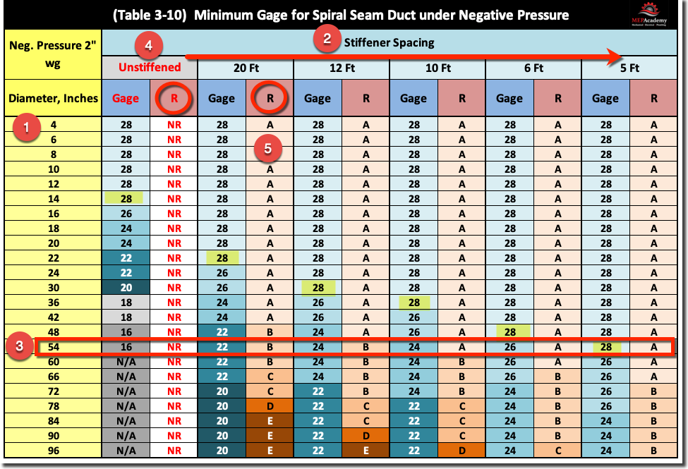
As you can see from the example above, as you increase the stiffener spacing (#2), you can reduce the thickness of the material, this is because the stiffener adds strength and rigidity to the duct allowing for a thinner material. Using an Unreinforced duct requires 16 gage material, while installing a stiffener every 5 feet allows you to use a much thinner and cheaper 28 gage duct.
The fabrication shop has to determine what their standard fabrication preference is and the cost for the various options based on stiffener spacing.
Now let’s look at chapter #8 on how to figure shop fabrication productivity.
Chapter #1 – Introduction to Sheet Shop Fabrication
Chapter #2 – Sheet Metal Materials
Chapter #3 – Sheet Metal Coil Line
Chapter #4 – Plasma Cutting Table
Chapter #5 – Spiral Machine
Chapter #6 – Sheet Metal Seams
Chapter #7 – Sheet Metal Joints
Chapter #8 – Sheet Metal Casings and Plenums
Chapter #9 – Sheet Metal Shop Fabrication Productivity
