


Chapter #3 – Sheet Metal Coil Line
Those fabrication shops that have invested in a coil line will find it less labor intensive to fabricate straight pieces of ductwork.
Sheet metal coil lines are available with many optional pieces of equipment that can be added on to perform an additional function on the path to creating a fully sectional piece of ductwork.
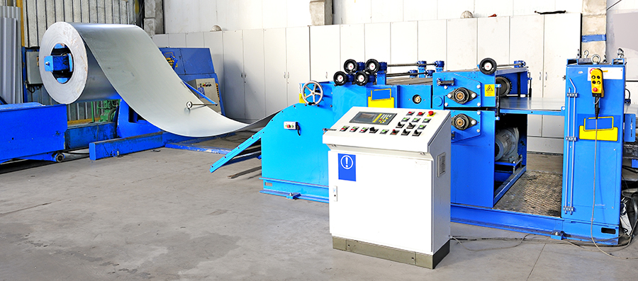
The full capabilities of the coil line begins where several rolls of differing gauges of metal are housed in large heavy rolls and end where the sheet metal is bent. Between the beginning and end are various pieces of fabrication equipment that perform special functions in the process of making a piece of duct for the HVAC industry.
Standard coil widths include 48” and 60”, which can make anywhere from a 4 foot to a 5 foot long piece of duct. Also, as an option are coil widths of 72” for a duct length of 6 feet, minus flange allocation. Gauges will range from 16ga to 30ga.
Remember when watching some of the shop fabrication videos below that fabrication shops are very noisy at times when the equipment and workers are in full operation, as they are working with sheet metal.
This first video will animate the total process. We recommend that once you finish this chapter that you watch this video again to identify all the steps you are going to learn about in this chapter.
Sheet Metal Coil Line
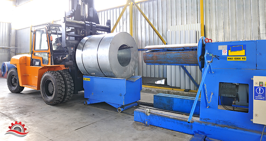
The below image shows that a forklift is being used to load the sheet metal coil onto a coil machine. These coils are very heavy and require machinery or an overhead crane system to load them onto the coil line equipment.
The coil line process steps are outlined below and are covered in greater detail later in this course.
- SHEET METAL COILS – Choose which coil width and gauge of sheet metal is required for the project.
- STRAIGHTENER/LEVELER – The process of straightening the sheet metal.
- BEADER – This stiffens the metal by putting a bead down the sheet metal
- NOTCHER – The notcher will cut out (notch) small portion of the duct at its edge where it will be bent
- SHEAR – This is when the sheet metal gets cut at the perfect point.
- SEAMERS – This machine installs the Snaplock or Pittsburgh seam along its length at the point where it will attach to the other side. One seam will be a female seam and the other male for a perfect fit.
- JOINT (Rollformer) – The metal has its end roll formed to create the ends of the duct that will join up to another piece of duct or a fitting.
- LINER – If required liner will be added.
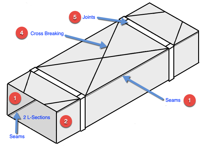
- BREAK – This is the final step in the automated coil line. This last piece of the coil line will bend the sheet metal into either an L-Section (2-sided), U-Section (3-sided) or Full-Wrap (4-sided)
Watch the video below and see if you can identify the various coil line steps in the process of forming a section of duct.
We begin with the coil of a particular width and gauge, which gets fed into the straightener. The purpose of the straightener/leveler is to remove the metals tendency to want to remain curled up as it was within the coil from the manufacture. After this it goes through the beader, which puts several beads across the sheet metal to stiffen it in its finished form.
Then the metal gets notched at the points where the metal will be bend so as to allow for and easy bend along its longitudinal length. The next section will shear the duct, cutting it at the perfect point along its length. The seaming section is next where it will have a female seam on one side and a male seam installed on the other by their respective seamers, such as a Snaplock or Pittsburgh seam.
Then the metal goes through the roll former, which creates the joint end of the sheet metal duct, such as TDC, Drive Slip or completely raw for the attachment of a proprietary joint such as Ductmate. Next liner will be added if the specifications call for the duct to have internal liner. The automatic duct liner feeds from a coil of liner material while applying a liner adhesive to the sheet metal and then automatically pins the liner to the sheet metal.
And finally the metal is bent using the break to create an L-Section (2-sided), U-Section (3-sided) or Full wrap (4-sided) section. The brake is a heavy duty hydraulic sheet metal bending machine that will fold your duct in preparation for assembling.
Step # 1 – Sheet Metal Coil Line
Galvanized steel is defined as a carbon steel sheet coated with zinc on both sides. Hot Dipped Galvanized for the HVAC industry is usually specified to be coated either as G-90 or G60. The coating indicates the amount of zinc applied to each side of the carbon steel. The most common gages used are from 16 ga through 26 ga. The use of the lighter gages are not as common in commercial construction as it is in residential construction.
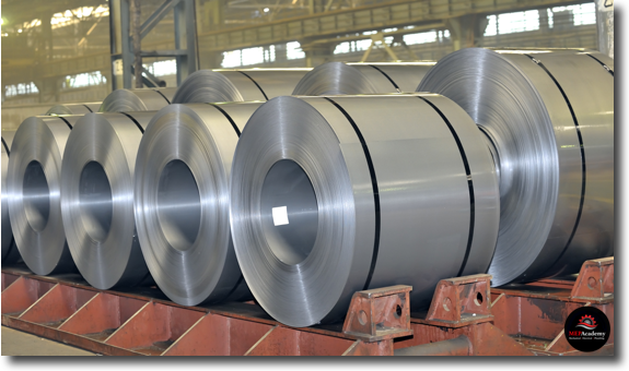
The most common width of the coils used in the HVAC industry is 36”, 48”, 60” and 72”, with the 60” width coil being the preferred width. The Wider the coil, the less joints you will need, as a 60” wide coil can make a 5 foot section of duct using Ductmate connectors, as opposed to only a 3’ foot section with a 36” coil width.
For example if you had 90 feet of straight duct, it would require;
- 30 pieces of 36” (3 foot) sections of duct 3’ x 30 = 90’
- 18 pieces of 60” (5 foot) sections of duct 5’ x 18 = 90’
It’s better to handle fewer pieces, in addition, the more pieces you have, the more it cost for gaskets, corner pieces and clips because you have 12 additional joints to make.
The coils are loaded onto the automated coil line using a forklift or overhead crane.
Step # 3 – Beading
The ductwork is Beaded or Cross Broken (#4) to provide strength across its surface area. Duct beading is the preferred method. The duct is run through a bead machine that puts a ridge or dimple across it transverse width every 12” or so. This will help reduce sagging of the metal.
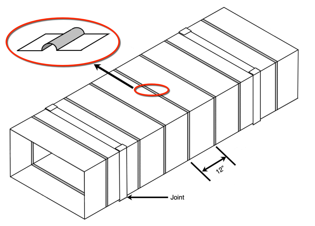
The purpose of cross-breaking or beading ductwork is to provide support for large spans of ductwork. For ducts that are 19” and greater in width and 10 Ft2 of unbraced panel area will require cross-breaking or beading. This requirement is for duct classifications of 3” static pressure and down and 20 gauge or less thickness. Ducts built to 4” static pressure or greater don’t require cross-breaking or beading as the increased thickness and reinforcement requirements provide the added support benefit. Beading is spaced every 12” apart, running parallel with the joint of duct, but direction of bead can be random on fittings.
Step # 4 – Notcher
The machine will notch the duct at the points where they need to be folded. The below image shows a four sided piece of sheet metal ductwork notched (#1) at the points that it will be bent by the Brake. The yellow highlight shows the line of folding (#2) that will happen with the brake in order to make the four sided piece of duct. Notching is how sheet metal is allowed to go through the roll forming machine where the joint is made.
The notching allows the roll-formed edge (#4), such as a TDC/TDF or S & Drive the ability to avoid the interference from bending at the corners. There is no way to bend the metal after its been through the joint (#4) making process without having the corners notched (#1). Ductmate doesn’t require notching as it isn’t put through the roll former, as it is an added flange that gets put on after the duct is assembled.
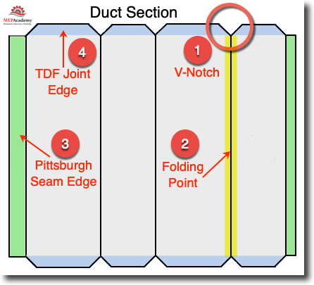
The depth of the notch is determined by which joint type will be applied to the end, such as TDC or S and Drive. TDC requires a deeper notch then S&D (S & Drive). There are different types of notching but they all have the same goal in mind.
Step # 5 – Sheet Metal Shear
Another piece of shop fabrication equipment is the shear, which comes in various forms, from automatic to manual. The fully completed coil line uses an automatic shear. The shear cuts the sheet metal at the point needed to give the proper width of duct.
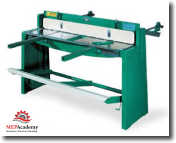
There are also hand held electric shears. Shown below is a manual stand-alone foot operated shear. Once the metal is position in the machine you push down with your foot on the long bar that near knee height.
Below are two videos, the first one is a short demonstration of a foot shear, the second is a longer video of the many steps in making a piece of sheet metal and the various tools used in marking and measuring.
This next video is a little over 8 minutes, but gives a good overview of the process of cutting a piece of sheet metal with a foot operated shear.
Step #6 – Sheet Metal Seams
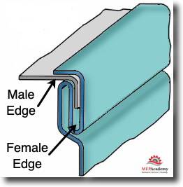
Seams are created along the longitudinal length of the duct or fitting to fasten one section to another, as opposed to joints that connect one length of duct section to another, or a joint of duct to a fitting. Seams seal to make one section of duct or a fitting.
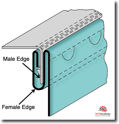
The longitudinal seam will be either Snap Lock or Pittsburgh Lock and is formed on a machine that will roll form the flat edges into one with a female and the other with a male end.
Pittsburgh seams are used on increased pressures, above those acceptable for Snap Lock.
The video below is a little grainy, but you can see that the rollers will bend the flat edge of the sheet metal, each successive roller bending the metal a little more until it reaches the shape required by the last roller. These machine is a stand-alone piece of equipment which in a complete coil line would be part of the automated process.
Step #7 – Roll Forming Machines
Depending on the seam type, the flat metal cut by the Coil Line or Plasma cutter will get put through the roll former to form a Snap Lock Seam or a Pittsburgh Seam. These are the two most common seams, so they are the ones we will be using through-out this training program. The seam takes two pieces of metal and locks them securely together. The seam runs longitudinal and the joint runs transverse.
Step #8 – Liner
Duct is often provided with internal liner for mostly acoustical reason and for its thermal properties for air ducts installed outdoors where wrapping duct is not practical because of the cost. The video below is of a portable pinspotter machine that is not part of the automated coil line, but will show you how liner pins are fasten to the duct to hold the liner in place.
In an automated coil line with a liner station, the metal will be sprayed with adhesive before the liner is applied, followed by the pins. In non-automated systems there will be a table area where the metal will be sprayed with adhesive before the liner is attached to the interior of the duct or fitting.
In the below video you will see several methods used in the coil line process for attaching liner to the duct, in addition you will see another manual method of attaching the pins that hold the liner in place.
Step #9 – Duct Break
Before the sections of duct can be assembled they need to be bent to form an “L-Shape”, “U-shape” or 4-sided single piece which comprises the duct. The break is a machine that is used to bend sheet metal. The metal is inserted to a point where the bend is required and then the machine automatically activates the break to bend the metal.
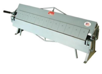
Some shops still use a manual hand break (shown above) where the operator pulls a lever which causes the machine to bend the metal. With this portion complete you now have two “L” sections, or a “U-Shaped” section that will match up along a male and female companion seam. For smaller ducts it might be possible to make the duct section out of a single piece. The seam gets knocked together either as a snap lock or Pittsburgh seam as described previously.
Watch this video to see how metal is bent using a brake. These types of brakes go by various names such as Box Brake, Finger Brake or Pan Brake. Notice how the shop worker inserts the notched section of the flat metal into the machines notch guide to position it correctly for where the fold will occur.
Duct Reinforcement
Reinforcement provides for the strengthening of the ductwork under certain conditions as dictated by the construction standards. The construction standards are driven by many factors including the pressure class, the size of the duct or fitting, the length of the duct and the local code adopted construction standards table.
Reinforcement can be accomplished by adding angles, channels, and Condu-locks with EMT. There are various other methods depending on the construction standards that provide jurisdiction over the project location. The standard could be an adoption of the SMACNA standards or the jurisdictions own version of something similar.
Coil Line Feeding a Plasma Cutter
Instead of having the coil line feed a sheet metal duct making process, it can feed lengths of coil duct onto a plasma cutter. This avoids having to purchase flat sheet stock and material handle each piece onto the plasma cutter. Watch the video below to see how a coil line machine can feed a plasma cutter to save time and money.
A Simplified Coil Line
In the below video you can hear the loud notching of the metal as the machine punches (notches) out at the point where the duct will be bent and or cut. The coil line machine cuts the section while creating a longitudinal seam, the point at where the duct sections will attach. The machine provides all aspect of the duct section, including straightening, beading, notching, joint formation, cutting, seams and bending.
The only thing the machine doesn’t do is the final banging together the single or two piece sections of duct along the seam. It also doesn’t install the corners pieces where the sections are bolted together.
Duct Assembling
Ductwork can be made into one, two or four pieces. One piece duct or full wrap duct is fabricated with one continuous piece of sheet metal and is limited in size by the fabrication equipment. As the duct gets larger and larger, more pieces will be required to make the duct. Two pieces (aka “L” sections, half sections, knocked down) are easier to ship, but more costly for the field labor, as they have to assemble the sections before installing.
Check what an “L” Section looks like coming off an automated break.
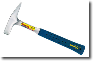
The Pittsburgh seams are knocked together with a Tinner’s Hammer or an automated tool that accomplishes the same thing, that is to bend over the seam to lock the sections together.
Coil Line (Fast Time Lapse Video)
This next video shows a shop worker knocking together sections of duct, installing the corner pieces and using an automatic Pittsburgh seamer to bend over the seam and lock the sections in place.
Now that you have an idea of what happens from the coil line to the end product, see if you can identify some of the following steps in this sped up video of a coil line. You’ll notice that when the sheet metal first appears in the video it has already been straighten, beaded and notched.
The next step you will see is the application of the male and female seams which is done under the white/beige colored metal boxes that protect the roll formers. Then it moves down to the roll formers that put the joints on each end, before finishing by being bent. Replay the video until you notice each of the steps being performed.
One more quick video from coil line to end product.
And one more that shows you a 4-sided, one piece wrap.
Making Square to Rounds
Making a square to round requires that you make small bends along the length of the square to round to form the shape. Fabrication shops use various pieces of equipment such as the break to make these small creases incrementally along its length to make the square to round. This can be done faster with this NAMCOR Striker machine. See the video below to get an understanding of how the machine makes a square to round.
Now let’s look at chapter #4 to see how using a Plasma Cutter can save on material waste and labor.
- Chapter #1 – Introduction to Sheet Shop Fabrication
- Chapter #2 – Sheet Metal Materials
- Chapter #3 – Sheet Metal Coil Line
- Chapter #4 – Plasma Cutting Table
- Chapter #5 – Spiral Machine
- Chapter #6 – Sheet Metal Seams
- Chapter #7 – Sheet Metal Joints
- Chapter #8 – Sheet Metal Shop Fabrication Productivity
- Chapter #9 – Casings and Plenums
