


 Overrides: Risks, Failures, and Best Practices")


In this article we’ll discuss the three different pumping methods used in a central plant for the distribution of chilled water. This includes primary variable flow, primary/secondary with distributed pumping, and primary/secondary variable flow with tertiary pumping. There are many other pumping configurations, but in this article we’ll cover the first three.
If you prefer to watch the video of this presentation, than scroll to the bottom.
Primary Variable Flow Chilled Water Pumping
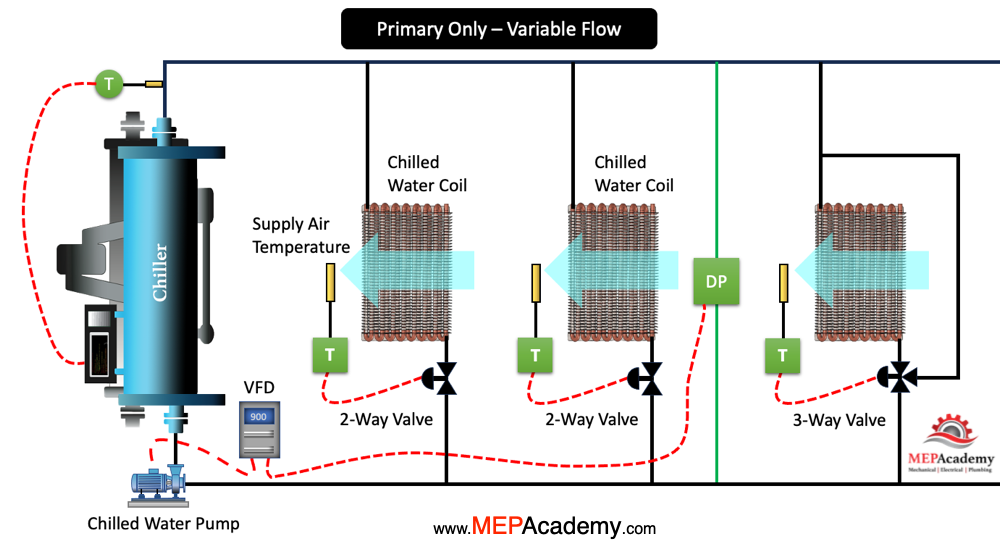
In a primary-only variable flow chilled water system, the operation is centered around using only primary pumps to circulate chilled water through the entire system. The key feature of this system is the variation of flow rates in response to the cooling load. This provides a more energy-efficient operation. Here’s an overview of how the primary-only variable flow chilled water system pumping arrangement typically works:
Chillers
Chilled water is generated by one or more chillers in the system. There is a chilled water temperature sensor in the chilled water supply pipe leaving the chiller. The chiller cools the water to the desired chilled water supply temperature before it is sent to the cooling coils.
The 3-way valve ensures that the chiller receives the minimum flow required by the chiller manufacturer. The 3-way valve bypasses the coil when the demand for cooling is reduced at this coil. This provides the chiller with a minimum amount of flow. There are better ways to do this that we’ll cover in another video.
The chilled water is then distributed to the various cooling loads, such as air handling units (AHUs), fan coil units (FCUs), or other cooling devices in the building. The chilled water is distributed using variable speed pumps.
Primary Chilled Water Pumps
The system relies on one or more primary chilled water pumps to circulate water through the chillers and the entire distribution system. These pumps are typically equipped with variable frequency drives (VFDs). The VFD’s adjust the pump speed and flow rates based on the demand. VFDs on the primary pumps allow for the adjustment of the pump speed to match the varying cooling load. Lower pump speeds during periods of lower demand contribute to energy savings. The demand is determined by a differential pressure sensor installed at a remote location.
Differential Pressure Sensor
The cooling coils have supply air temperature sensors that control the amount of chilled water flowing through the control valves. As demand in the space reduces, the 2-way valves modulate toward the closed position. This causes an increase in pressure within the chilled water system. This increase in pressure is sensed by the differential pressure sensor and is communicated to the VFD. The VFD then slows down the speed of the pump, which reduces the amount of chilled water circulated throughout the system.
Energy Efficiency
The system’s energy efficiency is enhanced by avoiding the need for secondary pumps and the associated energy consumption in a primary-secondary system. The variable flow nature ensures that the system operates at optimal conditions, minimizing energy wastage.
Dynamic Control in Central Plant
The system continuously adapts to changes in the cooling load. This provides dynamic control and improved efficiency over traditional constant flow systems.
This primary-only variable flow chilled water system offers a flexible and energy-efficient solution by adjusting the flow rates in the primary loop based on real-time cooling demand. It’s particularly suitable for applications where load variability is a significant factor.
Primary/Secondary with distributed Pumping
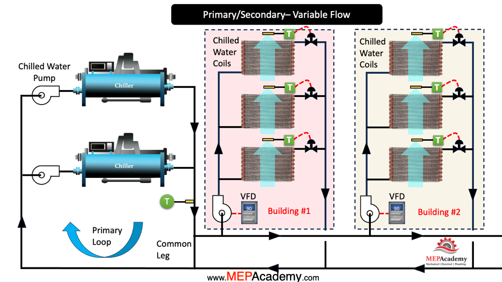
In a primary/secondary variable flow chilled water system with a distributed pumping arrangement, the operation involves two separate loops. There is a primary loop and a secondary loop. This design is often employed in larger and more complex chilled water systems, including more than one building. Here’s an overview of how the system typically operates:
Primary Chilled Water Pumps in Central Plant
One or more primary pumps circulate chilled water through the chillers and the primary loop. In this design there is a pump dedicated for each chiller. A common leg connects the primary and secondary loops.
Secondary Chilled Water Pumps
The secondary pumps are outside the central plant and into the buildings, bringing them closer to the cooling coils. The pumps provide the pressure required to bring the water from the common leg through their most remote coil and back to the common leg. These pumps will also operate using VFD’s to match the load of the coils they serve.
Energy Efficiency in Chilled Water Central Plant
The primary/secondary design allows for more precise control over the distribution of chilled water to the loads. This avoids over pressurizing the secondary loop which can occur when the secondary pumps are located within the central plant.
By separating the loops, the system can adapt to changes in the secondary loop without affecting the primary loop. Thereby contributing to overall energy efficiency.
Distributed pumping offers redundancy and flexibility, allowing for continued operation even if one secondary pump is offline for maintenance or repair.
This primary/secondary variable flow chilled water system with a distributed pumping arrangement is a robust solution for larger commercial buildings. This allows for precise control, energy efficiency, and redundancy are critical considerations.
Primary/Secondary Variable Flow with Tertiary Pumping
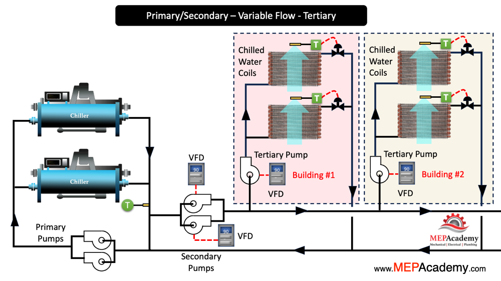
In a primary/secondary variable flow chilled water system with tertiary pumping, the operation involves three separate loops. There is a primary loop, a secondary loop, and a tertiary loop. This design is employed in large and complex chilled water systems to optimize control and enhance energy efficiency. The primary and secondary pumps can be located in the central plant, thereby allowing the tertiary pumps to be located in the individual buildings where the cooling coils are located. Here’s an overview of how the system typically chilled water pumping operates in this system:
Chilled Water Pumping
Primary chilled water pumps circulate chilled water through the chillers and the primary loop within the central plant.
Secondary chilled water pumps in the central plant circulate chilled water through the secondary loop. The secondary pumps respond to fluctuations in the cooling load requirements within the system using VFD’s.
Tertiary pumps circulate chilled water through the tertiary loop within each building. Tertiary pumping loops are dedicated to specific loads or areas that have unique cooling requirements. You might find this system on the campus of your local University which has a central plant and buildings distributed throughout the campus.
These pumps are provided with VFD’s to regulate the flow based on the specific needs of the tertiary loads within the building.
Variable Frequency Drives (VFDs):
Primary, secondary, and tertiary pumps are typically equipped with variable frequency drives (VFDs) to adjust pump speed and flow rates based on real-time demand. This flexibility ensures that the system operates efficiently under varying conditions.
Energy Efficiency in Central Plant
The primary/secondary/tertiary design allows for precise control over the distribution of chilled water to different types of loads with varying cooling requirements. By separating the loops, the system can adapt to changes in each loop without affecting the others, as a result it contributes to overall energy efficiency.
Dynamic Control and Redundancy
The system provides dynamic control, adapting to changes in the cooling load in real time for each loop. The inclusion of a tertiary loop offers additional redundancy and flexibility for meeting specific cooling needs.
This configuration provides a high level of control and efficiency, making it suitable for large and diverse commercial buildings with complex cooling demands.