Essential Tools for Every Refrigeration Technician: A Comprehensive Review
Are you intrigued by the inner workings of refrigeration systems and the vital role they play in our everyday lives? Whether you’re an aspiring refrigeration technician or a seasoned pro, understanding the tools of the trade is essential.
In this comprehensive review, we delve into the top tools that every refrigeration mechanic should have in their arsenal. These tools are not mere conveniences; they are the very instruments that empower technicians to diagnose, repair, and maintain refrigeration systems efficiently and effectively.
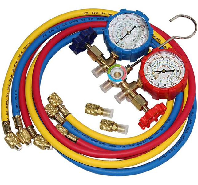
1. Manifold Gauge Set: Refrigeration mechanics rely on manifold gauge sets to simultaneously measure high and low side pressures in refrigeration systems. These sets are like the eyes of the technician, providing critical insights into the system’s condition. By providing real-time data, refrigerant gauges are essential for diagnosing issues and ensuring optimal system performance.
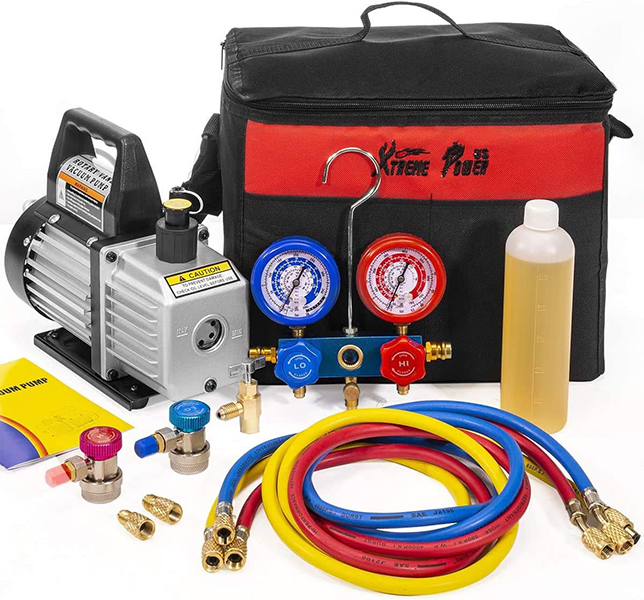
2. Vacuum Pump: A vacuum pump may seem unassuming, but its role is monumental. It evacuates air and moisture from refrigeration systems before the introduction of refrigerant, ensuring that the system operates efficiently without unwanted contaminants.
3. Leak Detection Tools: Finding elusive refrigerant leaks is a challenge without the right tools. Leak detection tools, including electronic detectors and bubble solutions, play a crucial role in environmental protection and system efficiency by pinpointing these leaks.
4. Digital Multimeter: An HVACR technician’s electrical diagnostic prowess relies heavily on a digital multimeter. This tool measures voltage, current, and resistance in electrical components, making it indispensable for troubleshooting electrical issues.
5. Pipe Cutters and Flaring Tools: Copper pipes are the lifeblood of many refrigeration systems, and pipe cutters and flaring tools ensure these essential components are accurately cut and shaped for the job.
6. Pipe Benders: The importance of smooth, kink-free bends in copper pipes cannot be overstated. Pipe benders are the secret to achieving these precise bends without compromising the integrity of the pipe.
7. Thermometers and Thermocouples: When it comes to temperature measurement, accuracy is key. Thermometers and thermocouples help technicians monitor temperatures at various points in the system, assisting in both diagnostics and cooling optimization.
8. Tubing Tools: Properly preparing tubing for installation is a fundamental step in any refrigeration project. Tubing tools, such as deburrers and reamers, ensure that tubing is ready for action.
9. Hex Key Set: Hexagonal screws and bolts are commonplace in refrigeration systems. A set of hex keys is a technician’s trusty companion for swiftly disassembling and reassembling components.
10. Oil Pump and Oil Injector: Lubricating oil is the lifeblood of compressors. Oil pumps and injectors ensure that the compressor functions optimally by delivering the right amount of lubrication.
11. Torque Wrench: Precision matters in refrigeration systems. Torque wrenches guarantee that bolts and nuts are tightened to precise specifications, safeguarding components and maintaining proper seals.
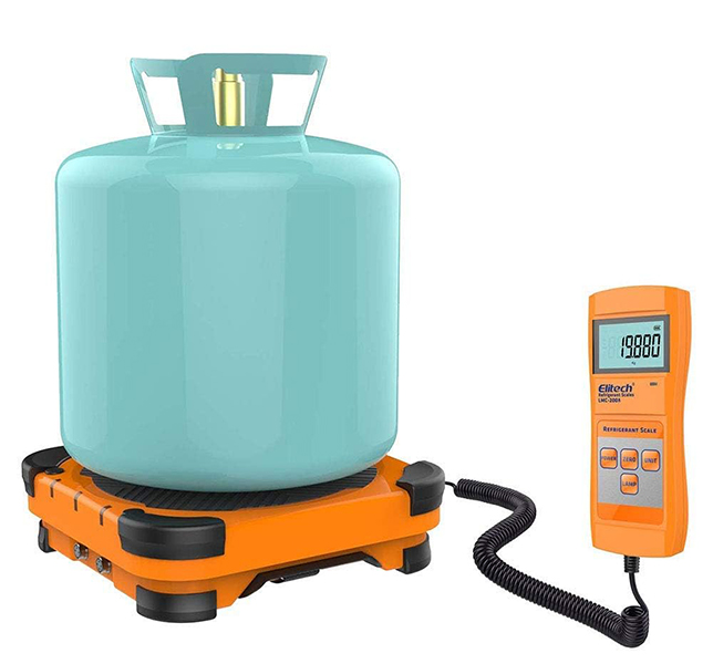
12. Digital Scale: In the intricate world of refrigeration, precision is paramount. This is where a digital scale steps in as a silent but indispensable partner for refrigeration mechanics. Why? Because refrigerants, lubricants, and various chemicals must be added to systems with meticulous accuracy.
A digital scale ensures that the right quantities are added, helping maintain the system’s efficiency, performance, and, perhaps most importantly, the environment. It’s not just about getting the job done; it’s about getting it done right, and that’s where the digital scale shines. So, let’s weigh in on the importance of this often-overlooked tool in the refrigeration technician’s toolkit.
These tools are the cornerstone of any refrigeration technician’s toolkit. Stay tuned as we dive deeper into each of these essential instruments, unveiling the art and science behind their usage, and why they’re indispensable for refrigeration technicians around the globe.
In this article we’ll answer a question that we get all the time. What filter, if any, can filter out the SARS-CoV-2 virus which leads to COVID-19, the disease? We’ll show you how efficient the different air filters are at filtering out various items for asthma and allergy sufferers, and the virus that leads to COVID-19.
If you prefer to watch the Video of this presentation, then scroll to the bottom or click on the following link. Air Filters vs COVID-19
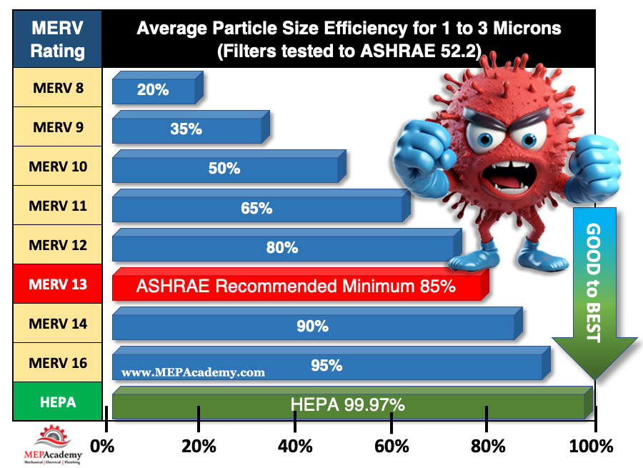
The ability of an air filter to remove microorganism, dust, pollen, dust mites, mold spores, pet dander, bacteria and viruses is indicated by a numerical value. This number, which is indicated as a MERV rating, states the filter’s efficiency at removing various sizes of these items. We’ll show you which filters, if any, work the best to protect you from these potentially harmful organisms.
MERV Rating
Minimum Efficiency Reporting Values, or MERVs, indicate the filter’s ability to capture larger particles, those 0.3 microns and larger. The higher the numerical rating, the greater the air filter is at removing particles from the air stream. A MERV-13 is better than a MERV-11 filter at removing particles, but how good are they against bacteria and a very small virus that leads to COVID-19.
Virus and Bacteria Removal
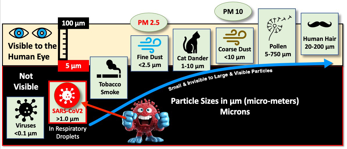
According to ASHRAE, research has shown that the particle size of the SARS-CoV-2 virus that leads to COVID-19 is around 0.1 microns. This is much smaller than what may be picked up by these air filters. As this chart shows, the virus lives in the invisible region, while others like dust, cat dander and human hair are visible to the human eye.
Sizes of various items shown in Microns. Invisible items in black area on chart, including the SARS-CoV-2 Virus.
Luckily, the SARS-CoV-2 virus doesn’t travel through the air own its own. It rides on respiratory droplets and droplet nuclei (dried respiratory droplets) that are predominately 1 micron in size and larger. These filters have various efficiencies at capturing the viruses that are in the 1-to-3-micron range according to ASHRAE.
The SARS-CoV-2 virus riding a respiratory droplet in the 1 to 3 micron range
ASHRAE
As the chart shows, ASHRAE recommends using a minimum of a MERV 13 filter, which is at least 85% efficient at capturing particles in the 1 to 3-micron size range. A MERV 14 filter is at least 90% efficient at capturing those same particles. High-efficiency particulate air (HEPA) filters are even more efficient at filtering human-generated infectious aerosols.
MERV Rating and Air Filter Efficiency for Particle sizes 1 to 3 microns in size
By definition, a HEPA air filter must be at least 99.97% efficient at capturing particles 0.3 micron in size. This 0.3-micron particle approximates the most penetrating particle size (MPPS) through the filter. HEPA filters are even more efficient at capturing particles larger AND smaller than the MPPS. Thus, HEPA air filters are more than 99.97% efficient at capturing airborne viral particles associated with SARS-CoV-2 which leads to COVID-19.
HEPA filters can capture and trap microorganisms, including viruses and bacteria, helping to reduce the risk of respiratory infections. So, if possible, use the highest MERV rated air filter with your system, or get a portable HEPA air filter for your room or office. HEPA filters are the most efficient at capturing small microorganisms like the SARS-CoV-2 virus.
Where are HEPA Filters used?
HEPA air filters are used in residential, commercial, and industrial facilities. In homes there are portable types that can be moved from room to room, and others that can be installed in a central air conditioning system serving the whole house.
HEPA air filters are also used along with ULPA filters in cleanrooms, labs, and other spaces requiring a very clean environment.
Asthma and Allergy Management
For individuals with asthma, HEPA filters help reduce asthma triggers like airborne irritants and respiratory allergens. According to the Asthma and Allergy Foundation of America (AAFA), nearly 26 million people have asthma in the United States. There are 4.8 million children under the age of 18, and nearly 21 million adults suffering from asthma. On average, 10 people in the unites States die every day from asthma. A total of 3,517 deaths in 2021.
According to the AAFA over 100 million people each year in the United States experience various types of allergies. Allergies are the sixth leading cause of chronic illness in the U.S. HEPA filters are highly effective at removing allergens such as pollen, dust mites, and pet dander, providing relief to allergy sufferers.
Editorial Process:
Some of the links in this article may be affiliate links, which can provide compensation to the MEPAcademy at no cost to you if you decide to purchase. Our reviews and articles are made by an industry professional experienced in the engineering and construction of commercial buildings.
Are you paying too much for your HVAC equipment? How do you know if the quote you received for your equipment is a fair price? Do you have a method of comparing what you have paid for various HVAC equipment with what is being quoted currently?
Keeping track of the cost of HVAC Equipment allows you to quickly provide budgets and check the cost of equipment before you purchase. This database allows you to easily keep track of the most common HVAC equipment.
HVAC Equipment Cost Database
Using an HVAC Equipment cost database will save you a lot of money by avoiding the costly mistake of paying too much for equipment.
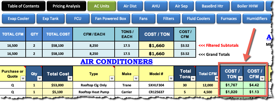
Air Conditioners in Historical Pricing HVAC Equipment Database
The HVAC Equipment Cost database keeps track of all your equipment quotes or purchases for easy reference and parametric checks, such as cost per ton ($/Ton), cost per CFM ($/CFM)
For an HVAC Piping Estimators the need for quick budgets for the installation of piping is best handled with a spreadsheet of different material types and sizes. Having an estimating software program can make this process a lot easier, as the material pricing is always up to date and can be entered into the spreadsheet quickly. You can get a copy of this spreadsheet to help you price piping fast and efficiently.
HVAC Piping Unit Pricing Calculator
HVAC PIPING UNIT PRICING
Often the requirements of the RFP or bidding instructions will call for the price per foot to install piping beyond that which is required by the contract drawings. Such pricing maybe used for change-orders. Having these numbers available and updated often also gives you a quick reference for budgeting projects. It’s good to know when doing job site comparisons of different piping options or during discussions with engineering, what the cost is for the various piping sizes and types of materials.
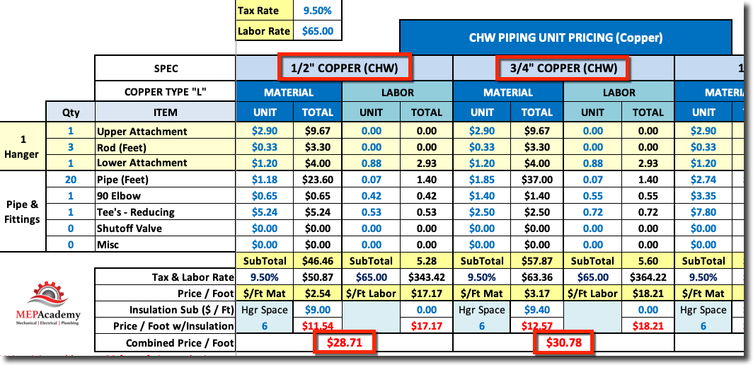
HVAC Piping Unit Pricing Calculator for Copper and Carbon Steel from 1/2″ to 14″
COST PER FOOT
The cost per foot for the installation of piping needs to include fittings and hangers prorated into the value. It’s best to look at a standard length of pipe and then figure that you will have a Tee and 90 degree elbow in that length.
So for example, using twenty feet of copper water pipe with a Tee and 90 degree elbow plus the hangers to build a unit price would represent a field condition of a fitting every ten feet.
For higher density projects like Hospitals you could put more fittings in your unit pricing. Total those cost up and then divide by 20 to derive at a cost per foot for that particular size and material type.
20 feet of pipe + 2 Fittings + 3 Hangers / 20 = Cost per Foot
If the piping is insulated, you can also put the values in for insulation.
The Estimating Wizard provides two spreadsheets for tracking unit pricing, one for HVAC Piping and the other for Plumbing piping. Get a copy and start tracking your cost per foot, or be prepared to give a quick budget based on your knowledge from your spreadsheet of unit prices. Watch the video below to see how quick and easy it is to track the cost per foot for various sizes and material types.
MEP Academy HVAC Piping Unit Pricing Spreadsheet
The MEP Academy provides a spreadsheet that makes calculating unit pricing simple. The spreadsheet is available by following this link, HVAC Piping Unit Pricing Spreadsheet
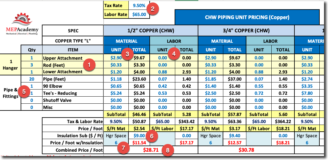
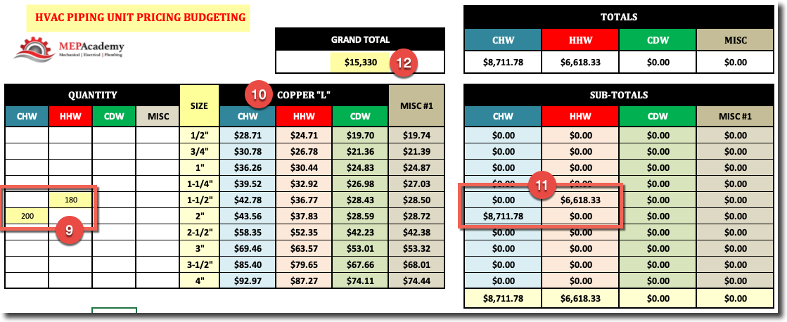
HVAC Piping Unit Pricing Calculator Example
In the screenshot above there is a place for you to build your hanger requirements (#1), and a place to put your tax rate and hourly labor rate (#2).
For each size of pipe and material type you would insert the unit cost for Material (#3) and Labor (#4).
Under item (#5) you would build your typical run of pipe and enter the quantity of fittings you might expect for the type of building and system. You would add whatever you think will be required for every so many feet of pipe. In the example above we are showing that for every 20 feet of pipe you will have 1 Elbow and 1 Reducing Tee.
Under item (#6) you would add the cost per lineal foot for insulation if required. You could also look at insulation as a separate value and leave the pipe bare.
Line item (#7) is where you indicate the hanger spacing, and for each hanger you defined under item (#1) you will get the quantity as defined by the linear feet in item (#5) divided by your hanger spacing, which will affect your cost.
Line item (#8) is the calculated cost per linear foot of piping for that size and material type of pipe.
Summary Sheet
After you have all your unit pricing information inputted into the spreadsheet, all you have to do to get a budget for installing piping is to enter the quantity of piping (#9) for each size and material type (#10). The system will automatically calculate the cost (#11) to install that run of piping based on your unit pricing data. The total cost will be shown at the top of the spreadsheet (#12).
The proper sizing and layout of condensate drain lines is important for the protection of property and for the proper functioning of the air conditioning equipment.
If you prefer to watch our YouTube version of this presentation, scroll to the bottom.
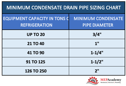
Condensate Drain Pipe Sizing
The size required for the condensate pipe is dictated by the local code. Enclosed you will find the requirements for many local codes, but be sure to check your code for your local requirements. If the outlet size of the equipment’s condensate drain is larger than what’s shown in this chart then your required to use the larger outlet size.
Minimum Condensate Drain Pipe Sizing Chart
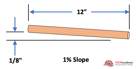
Slope to be at least 1/8” per foot or 1 percent, that is for every 12” horizontally there must be at least an 1/8” drop vertically.
Condensate drain piping to slope a minimum of 1/8″ per every 12″ horizontal
Attics or Furred Spaces
If the Air Conditioner is suspended above an inaccessible ceiling, such as a gypsum board ceiling or attic space then you will need to provide a means for protecting the building elements from the overflow of the primary drain and for indicating that there is a leak.
Also, drain pans that are poorly drained can cause water to stay in the pan risking the possibility of algae and bacteria growth. Below are some possible solutions, but as always check your local code for the approved method.
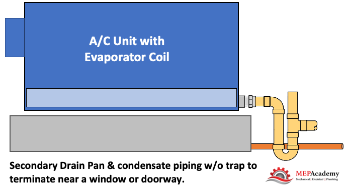
Option 1 – Secondary drain pan with drain piping. This would hang below the Air Conditioning unit in case the A/C units primary pan overflowed. Also, there is a requirement to provide secondary drain piping to a point of termination that would provide notification to the occupants that there is a leak, such as terminating above a window or doorway.
Option 1 – Secondary drain pan with piping terminating in observable location
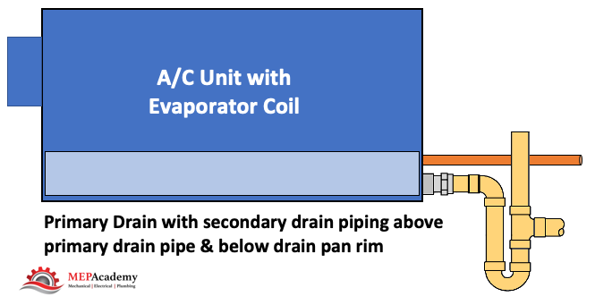
Option 2 – An additional drain pipe connection that sits above the primary drain connection and whereby the secondary drain piping terminates in a location to alert the occupants of the clogged primary drain.
Option 2 – Secondary drain piping connection to primary drain pan
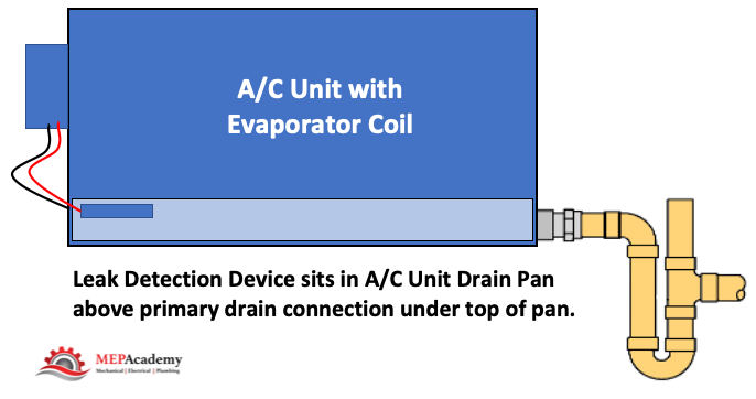
Option 3 – Leak detection device that automatically shuts down the Air Conditioner if the primary drain becomes clogged.
Option 3 – Primary drain with leak detection device
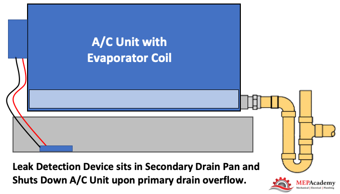
Option 4 – Secondary drain pan with leak detection, located beneath the coil that shuts down the unit upon a leak.
Option 4 – Secondary drain pan with leak detection
The additional drain pan or drain pan connection shall be provided with a drain pipe that will determinate in an observable area, such as in front a window or above a doorway, and be of a size not less than 3/4”. Secondary drain pan shall not be less than 1-1/2” in height and extend 3” wider on each side of the coil or AC unit.
Secondary drain piping terminating above window. Pipe doesn’t have to be visible as shown.
Drain Termination
Where can and can’t you terminate the air conditioners condensate drain piping? There are several options where you can terminate the condensate drain line;
Indirect Drain
Condensate Pump to Indirect Drain
Drywell
Leach pits
Landscaped areas that are properly designed to handle the volume of condensate
To Properly designed stormwater treatment systems.
Indirect Drain
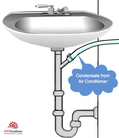
Lavatory tailpiece in the same tenant space as the air conditioner
Laundry standpipe
Janitors Sink
Inlet of Bathtub Overflow – Must be accessible
Collect and send to cooling tower (See description below)
Cooling Coil condensate to sink tailpiece.
The connection to a plumbing fixtures tailpiece has to be made within the same tenant space as the air conditioner cooling coil that is generating the condensate.
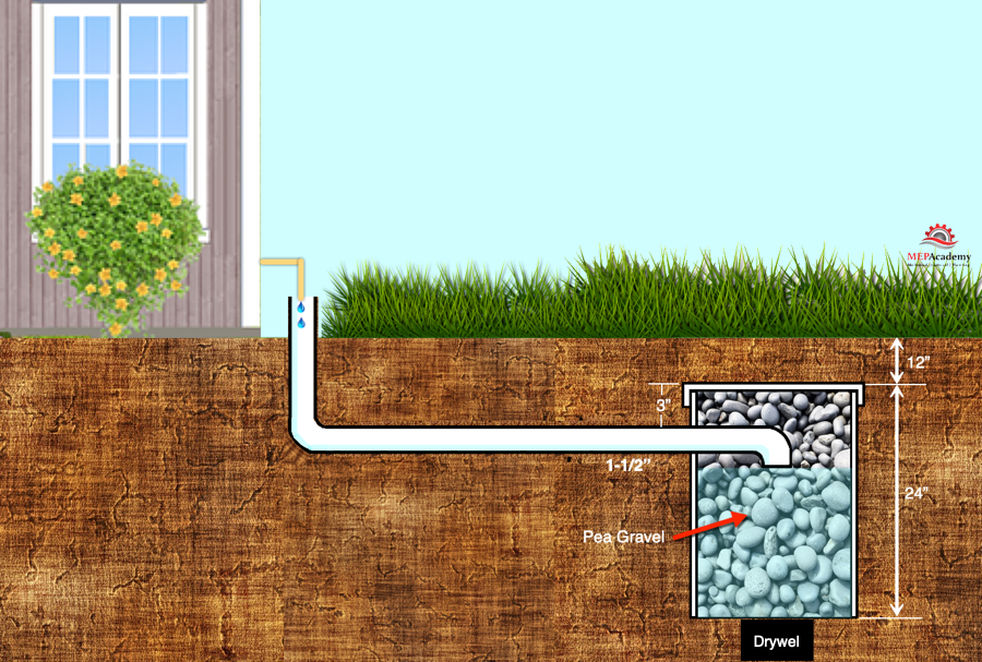
Drywell
A drywell can be used for the termination of your air conditioners condensate drain. Check your local code for the specifics, but generally it includes some or all of the following depending on whether it’s for residential or a commercial project:
A minimum size hole, such as 2 foot by 2 foot by 3 feet deep, or a round hole such as 12” diameter by 3 feet deep.
A minimum of 6” of soil or concrete shall provide cover above the rocks
Some form of barrier between the soil and the top of the drywell where the rock begins, such as building paper or plastic
Drywell to be filled with gravel or crushed rock, often with a stated minimum size rock such as 1 inch diameter
The termination of the condensate drain pipe shall connect indirectly to the drywell drain pipe.
The drywell drain pipe to be a minimum of 1-1/2” PVC or other approved material.
Drywell to be at least three feet away from the building structure or any footings.
Drywall for Air Conditioner Cooling Coil Condensate
There are various methods of providing drywells depending on the local code. There are prefabricated drywells that can be used and ones that are made by using a large diameter piece of PVC pipe or similar material.
Some codes will require you to collect the condensate from cooling coil drain pans and return it to the cooling tower if the equipment is served by a cooling tower and the total combined capacity of the HVAC cooling coils exceeds a certain amount like 65,000 btu/hr.
This is a water conservation measure, and there are some exceptions to this requirement, such as if the total capacity of the AC Equipment cooling coils are less than 10% of the total capacity of the cooling tower, or if the location of those AC Cooling coils are in a remote location, far from the tower.
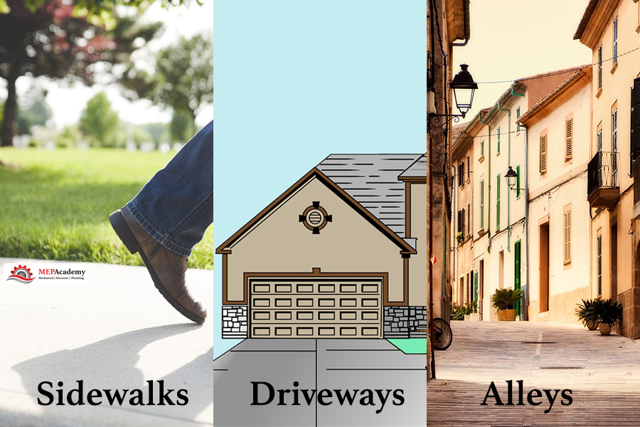
Some locations where you can’t terminate condensate;
Public ways
Sidewalks
Driveways
Alleys
No termination of condensate on public area ways
Excluded from Code Requirements
Excluded from these codes are non-condensing type of equipment like radiant cooling panels that are designed to prevent condensate from occurring by keeping the temperature of the chilled water above the dew point temperature/vapor pressure of the surrounding air. These are system designed to operate in sensible cooling only modes.
Piping Material
The material types that can be used for condensate drain piping varies by jurisdiction but the most commonly cited materials are:
Copper
PVC – DWV
CPVC
ABS – DWV
Polyethylene
Galvanized steel
Cast iron.
Also the use of short radius 90-degree elbows are often prohibited. You can normally use standard fittings until you reach a certain size at which point you might be required to use drainage pattern fittings (DWV)
Traps
Traps are to be installed as required per the manufactures recommendation. No traps are required on the secondary drain pan, this is to allow immediate notification that the primary drain has failed.
Cleanouts
Cleanouts are required in case of plugged drain pipes. Provide as required to prevent the need to cut drain pipes for unplugging. Some of the following maybe used for cleanouts if approved by your local code authority;
Plugged tees
Union connections
Short clamped hoses at the unit (see image above)
When you have more than one air conditioning unit condensate tied to a main condensate pipe, then every change of direction shall have some method of cleanout. Check your local code as this maybe a requirement for even a single air conditioners condensate piping.
Condensate Pumps
Condensate pumps can be used to elevate the condensate vertically to a point where it will then discharge into a code approved gravity sloping condensate drain line. The condensate pump should be interlocked with the Air Conditioning Unit to prevent its operations if the condensate pump is inoperable.
Please remember that code requirements are always changing, so check for the most current code in your area at the time of design and installation. Or ask an inspector for the current installation practice.
Having an MEP Academy Estimating Spreadsheet that automates portions of your estimates, will save you valuable time that could be used to make more sales. All aspects of the cost of furnishing and installing an HVAC and/or a Plumbing system is contained in one spreadsheet made specifically for the MEP industry. For plumbing only see below.
For a Plumbing only Spreadsheet, use this Commercial & Residential Version. Plumbing Only. For a simple Residential HVAC & Plumbing Spreadsheet. Residential version.
Dashboard
The Main Dashboard provides you with all the information you need to make a quick decision on whether to make further adjustments, or if one of the metrics looks out of place based on historical data. The Dashboard gives you a quick overview of all that is going on within the Estimating Spreadsheet.
Estimating Dashboard within the MEP Academy Estimating Spreadsheet
Your MEP Academy Estimating Spreadsheet needs to be able to handle rental equipment, general conditions, subcontractors, piping and plumbing takeoffs, sheet metal, labor rate tables with crew mix capabilities, , and a bid summary. Each sheet in the estimating spreadsheet automatically calculates the values you enter, showing you a new total bid amount.
Will cover portions of the MEP AcademyEstimating Spreadsheet starting at the back of the Excel spreadsheet and working our way toward the front summary page last.
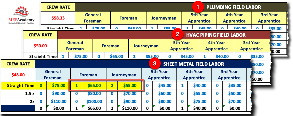
Choose your crew mix based on the level of experience and the different pay scales based on each project. Pick any combination and quantity of tradesman based on the requirements of the project.
Labor Rates and Crew Size within the MEP Academy Estimating Spreadsheet
There is a separate crew labor rate for HVAC Piping Shop & Field, Sheet Metal Shop & Field, and Plumbing.
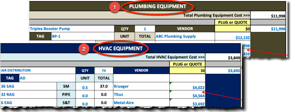
Enter the project equipment price and labor to rig the HVAC and Plumbing equipment into place. Compare supplier pricing easily side by side. The MEP Academy Estimating Spreadsheet automatically selects the lowest bidder but lets you override that decision.
HVAC Equipment page within the Estimating SpreadsheetHVAC & Plumbing Equipment Sheets
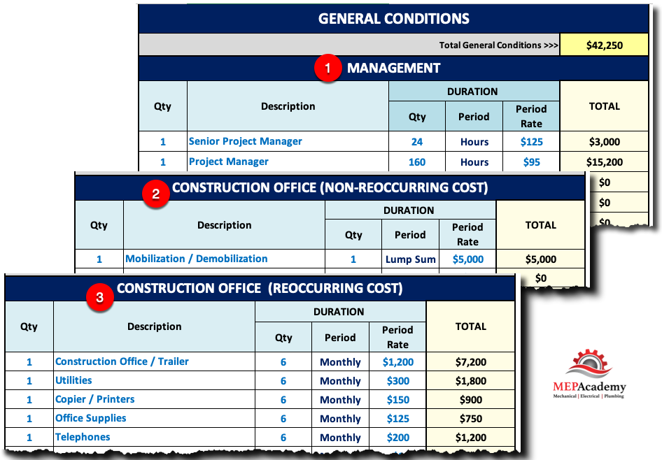
Do you need a jobsite trailer or onsite management? Enter the quantity and level of the staff required to run the project, whether one person or dozens. Set the quantity and duration of each general condition, along with the rate. General Conditions is broken down into three sections as follows: #1 – Management, #2 – Construction Office (Non-Reoccurring Expenses), and #3 – Construction Office (Reoccurring Expenses).
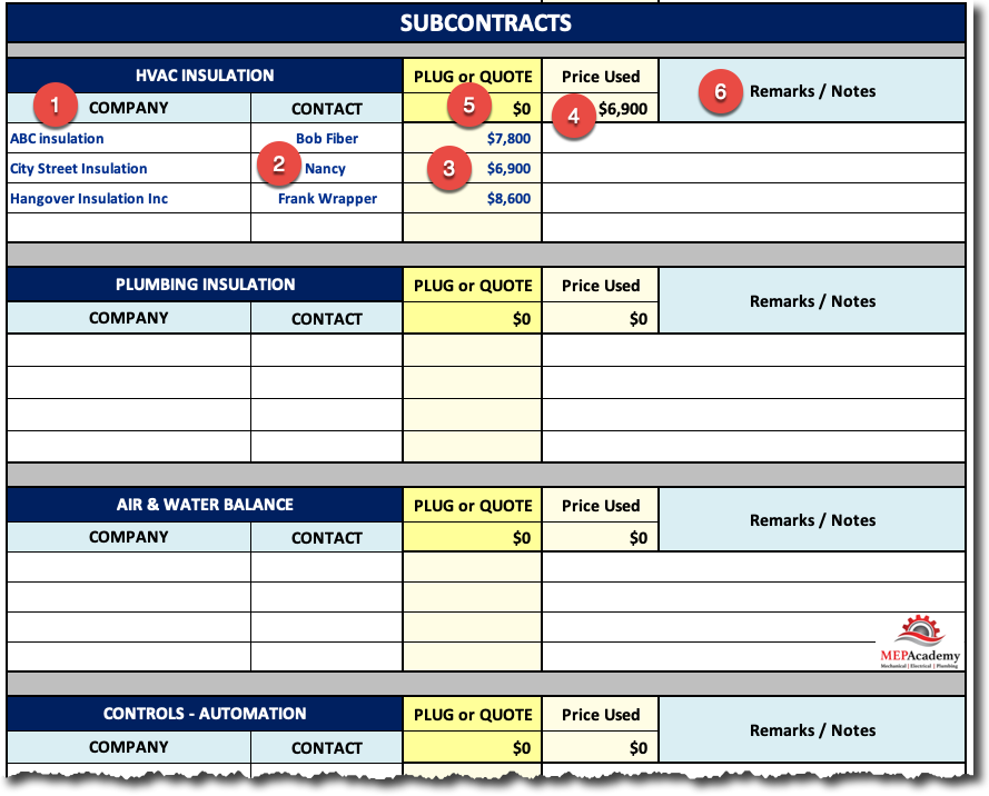
HVAC & Plumbing contractors often subcontract out for Air & Water Balance, Sheet Metal & Piping Insulation, Water Treatment, Building Automation, Excavation and other specialty trades that they don’t self-perform. This spreadsheet was made especially for the HVAC & Plumbing contractor and their most often used subcontractors.
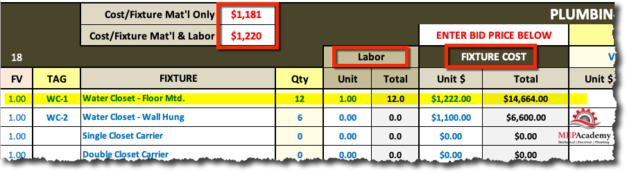
For those contractors that do plumbing the following Plumbing Fixture sheet will give you a place to record your vendors quotes and the labor it takes to install each type of fixture. What is also revealed is the overall cost per fixture.
Plumbing Fixtures page within the Estimating Spreadsheet
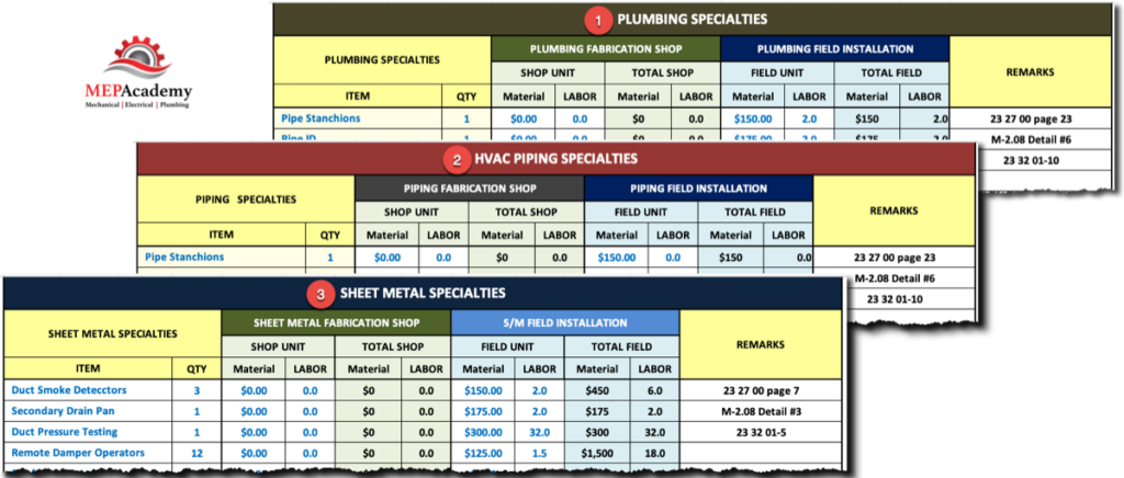
Each trade has a specialty sheet for those items that aren’t considered equipment or a fixture, but for which there is a cost impact. The MEP Academy Estimating Spreadsheet includes Sheet Metal, HVAC Piping & Plumbing Specialty sheets.
HVAC and Plumbing Specialty Pages within the Estimating SpreadsheetSpecialty Sheets in Estimate Spreadsheet
Material & Labor Summary Sheets
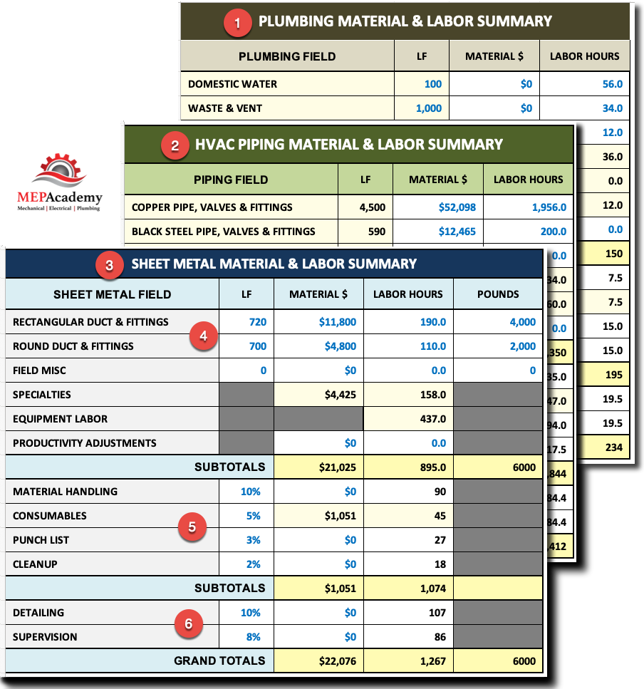
You will find a Sheet Metal, HVAC Piping & Plumbing material & labor summary sheets where all of the other specialty sheets are summarized for your review and last minute edits. Each sheet will be divided between field & shop fabrication work. The first section covers the field installation items.
Sheet Metal Material and Labor Summary – Estimating Spreadsheet
Each of the field labor summary sheets contain a row to add for the following
Material Handling
Consumables
Punch List
Cleanup
Detailing
Supervision
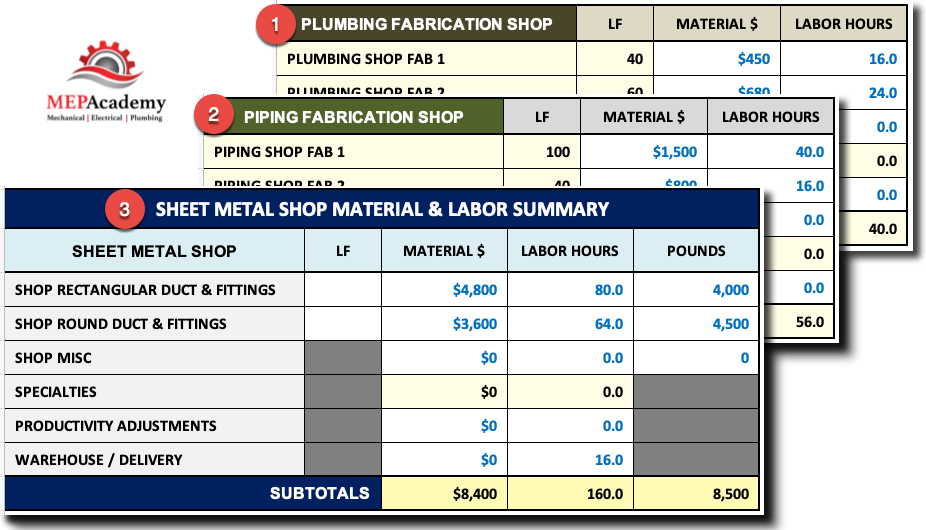
Shop Fabrication Summary Section
For those of you that have a fabrication shop, there is a section to add material and labor.
Shop Fabrication Summary
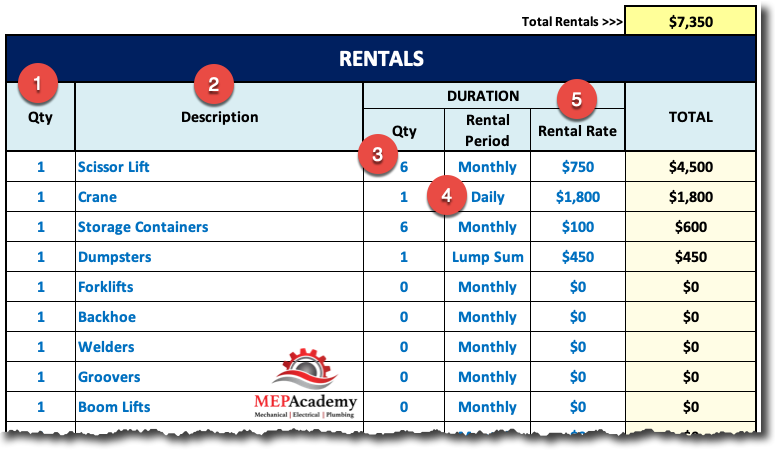
Rentals
For those HVAC air conditioning and Plumbing projects that require a crane, fork lift, scissor lift or any other equipment that you don’t own but will be required on the project. Having a spreadsheet that maintains a list of the most common equipment you normally rent along with their rental rate will save you time and money while avoiding having to call for pricing on every job.
Rental Sheet in Estimating Spreadsheet
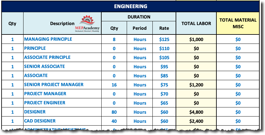
Engineering
If you do your own design then you should have a sheet of each of the personnel responsible for spending time on the engineering task. If you’re doing design/build work, but don’t do the engineering yourself, but hire a third party, then you should add some engineering review time. It’s your responsibility to manage your third-party engineer to make sure they design within your cost parameters.
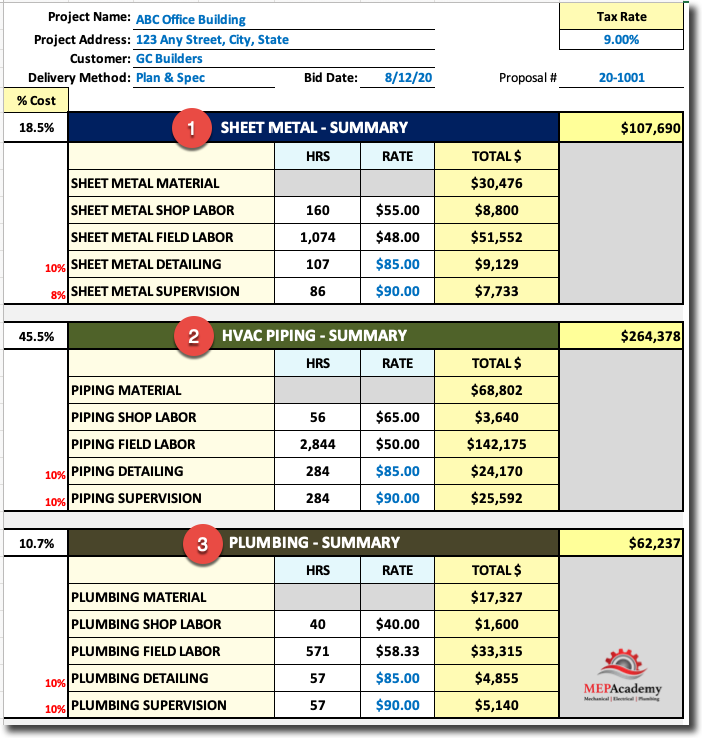
All of your estimates are summarized on the last tab of the MEP Academy Estimating Spreadsheet for easy review. You can quickly scan each of the categories to see where all the project cost has shown up. There is the labor and material summary for HVAC Sheet Metal, HVAC Piping, and Plumbing and another section for Subcontractors, General Conditions, Rentals, etc.
Estimating Spreadsheet Summary PageMEP Academy Estimating Spreadsheet Summary
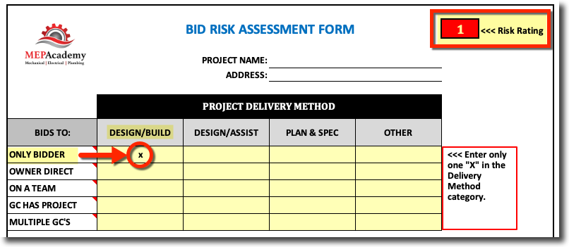
The MEP Academy Estimating Spreadsheet contains a bid risk assessment form that rates the success of winning any particular project that you are contemplating pursuing. The risk assessment form will help you determine if the project is worth bidding based on a set of questions that rate your answers.
Bid Risk Assessment
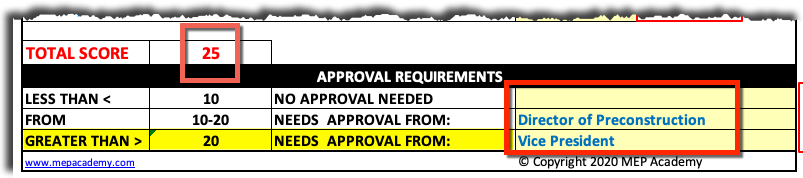
The answers to these questions will give you a score from which you can use to see how the project rates on a scale of risk and reward. The total risk assessment score will also inform you which level of approval is required within your company depending on how you rate your risk values as the example shown below. The total score is 25, which according to this contractor would require the Vice President to sign-off on the project or approve the decision to pursue bidding on the project.
The MEP Academy Estimating Spreadsheet is used to gather all the information for estimating a project, putting it into a format where you can make quick adjustments and decisions while the spreadsheet gives you an immediate update on the price.
Purchase this spreadsheet at its currently reduced price of ONLY $245.00, which usually sells for $599.00
Watch the YouTube video below to see the MEP Academy Estimating Spreadsheet in action.
Artificial intelligence is changing data centers faster than any technological shift in decades. As AI processors become more powerful, they consume more electricity and generate unprecedented amounts of heat. That heat must be removed efficiently, or the servers will overheat, throttle performance, or even fail.
For years, data centers have relied on sophisticated air-cooling systems to keep servers operating within safe temperature limits. Cold air is delivered to the front of server racks, server fans pull that air across processors and memory, and the heated air is exhausted into a hot aisle where mechanical cooling systems remove the heat from the building.
This approach has served the industry remarkably well.
However, today’s AI servers are creating a new engineering challenge.
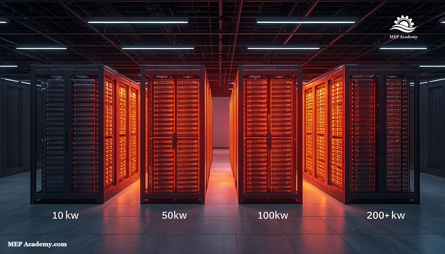
Modern AI racks can consume well over 100 kilowatts of power, and some next-generation deployments are approaching or exceeding 200 kilowatts per rack. At these power densities, simply moving more air through the data hall becomes increasingly difficult, inefficient, and expensive.
The industry is reaching a point where traditional air cooling is no longer the most practical solution for every application.
That’s why many of the world’s largest technology companies are investing heavily in immersion cooling.
Immersion cooling tanks fill a data center
Unlike conventional cooling systems that cool the surrounding room, immersion cooling places the servers directly into a specially engineered dielectric liquid that safely absorbs heat from the electronic components. Because the fluid does not conduct electricity, the servers continue operating normally while completely submerged.
At first glance, the concept seems almost unbelievable.
After all, we’ve all been taught that electronics and liquids don’t mix.
Yet immersion cooling is rapidly becoming one of the most promising technologies for supporting artificial intelligence, machine learning, high-performance computing (HPC), scientific research, and other extremely demanding computing applications.
In this article, we’ll explain:
What immersion cooling is
Why AI is driving its rapid adoption
How immersion cooling actually works
The difference between single-phase and two-phase immersion cooling
How heat ultimately leaves the building
The advantages and disadvantages of immersion cooling
Why future AI data centers may look completely different from today’s facilities
Whether you’re a mechanical engineer, contractor, estimator, project manager, facility engineer, data center professional, or simply curious about the technology powering artificial intelligence, understanding immersion cooling provides valuable insight into where the industry is heading.
Why Traditional Air Cooling Is Reaching Its Limits
To understand why immersion cooling is gaining attention, it’s important to first understand the limitations of conventional air cooling.
In a traditional data center, cooling follows a relatively straightforward process:
Computer Room Air Handlers (CRAHs), Computer Room Air Conditioners (CRACs), or other cooling equipment supply cold air to the data hall.
Cold air enters the front of each server rack through the cold aisle.
Thousands of small server fans pull that air across CPUs, GPUs, memory modules, power supplies, and other electronic components.
The air absorbs heat generated by the equipment.
Hot air exits the rear of the racks into the hot aisle.
Mechanical cooling equipment removes that heat from the building before the cycle repeats.
For decades, this approach worked exceptionally well because server power densities remained relatively low.
Increased Computing Demand
As computing requirements increased, however, rack power consumption climbed steadily:
5–10 kW per rack
15–20 kW per rack
30–50 kW per rack
60–100 kW per rack
Now, AI is pushing rack densities to levels that were once considered impossible.
Moving enough air to cool these systems presents several challenges:
Larger server fans consume more electrical power.
Higher airflow increases pressure losses.
Cooling equipment becomes larger and more complex.
Mechanical infrastructure occupies more building space.
In simple terms, air is no longer the ideal medium for transporting extremely large amounts of heat.
Liquid, on the other hand, is far more effective.
Because liquids have much greater density and heat capacity than air, they can absorb and transport significantly more thermal energy using far less volume.
Instead of moving enormous quantities of air through an entire room, immersion cooling removes heat directly where it is generated—inside the server itself.
This fundamental shift is changing how engineers think about cooling AI infrastructure.
How Immersion Cooling Works
The concept behind immersion cooling is surprisingly straightforward.
Instead of cooling the room…
The cooling system cools the servers directly.
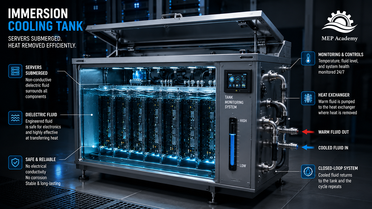
Immersion Cooling Tank for Servers
Servers are installed inside specially designed tanks filled with a dielectric fluid. Unlike water, dielectric fluids do not conduct electricity, allowing electronic components to operate safely while completely submerged.
As processors, graphics processing units (GPUs), memory modules, and other electronic components generate heat, that heat transfers directly into the surrounding liquid.
The warmed dielectric fluid then circulates through a heat exchanger, where its heat is transferred into a separate facility water loop. After the fluid is cooled, it returns to the immersion tank, where the cycle repeats continuously.
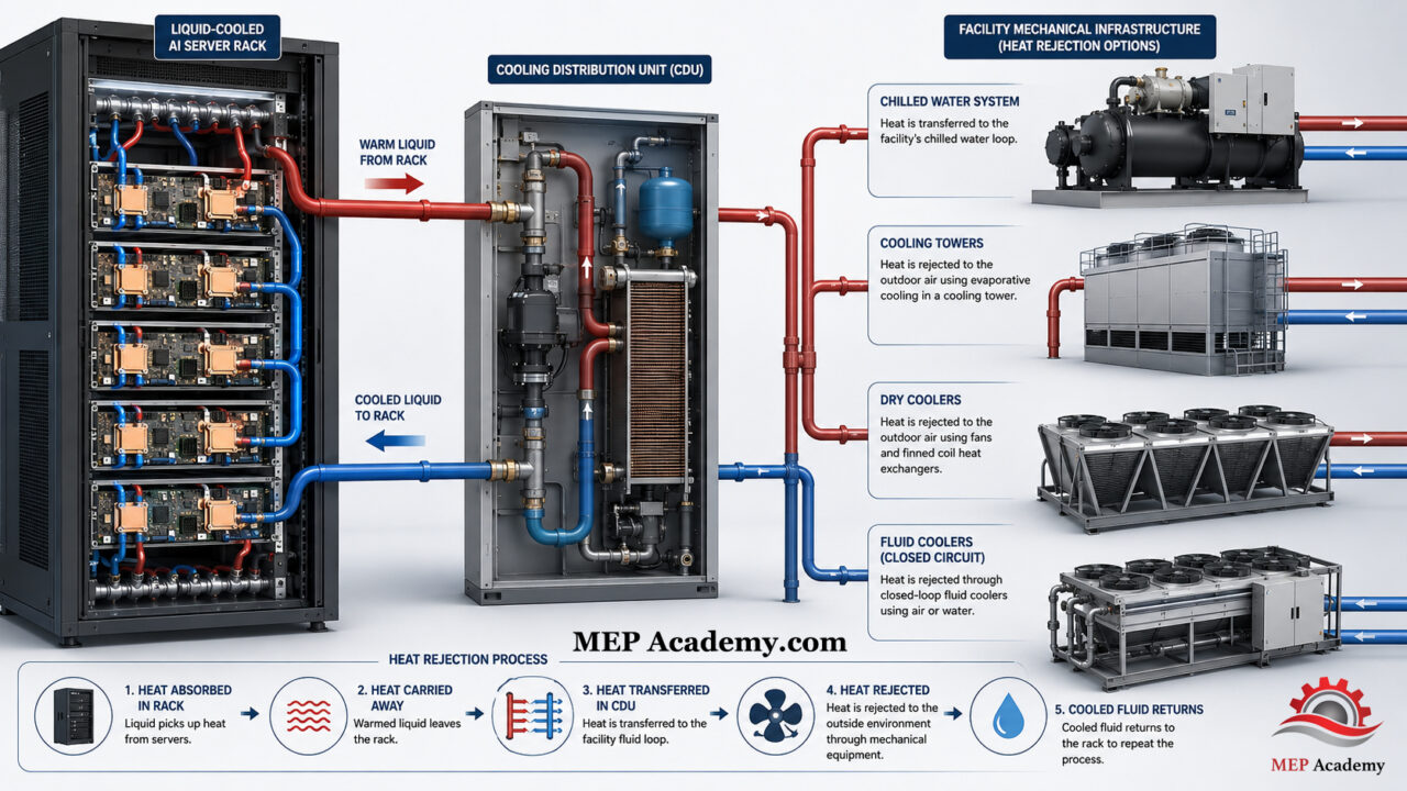
The building’s mechanical cooling system still plays an important role. The heat absorbed by the dielectric fluid is ultimately rejected outdoors through cooling towers, dry coolers, fluid coolers, or chilled water systems, depending on the facility design.
The key difference is that the servers are no longer cooled by moving massive amounts of air through the data hall. Instead, heat is captured immediately at its source and transported efficiently by liquid.
This overview explains how immersion cooling works, why AI is accelerating its adoption, and how it differs from conventional air-cooled data center designs.
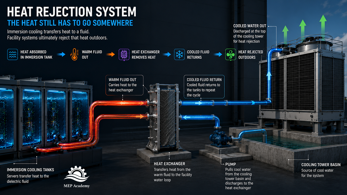
How It Works Diagram
Heat Rejection from Immersion Cooling System in a Data Center
The simplified diagram illustrates the basic heat flow through an immersion cooling system.
Servers generate heat while operating inside a dielectric fluid.
The dielectric fluid absorbs heat from the electronic components.
Warm dielectric fluid flows through a heat exchanger.
Heat transfers into the facility water loop.
Cooling water is pumped from the cooling tower basin through the heat exchanger.
Warm condenser water returns to the top of the cooling tower.
The cooling tower rejects the heat to the atmosphere.
The cooled water collects in the basin, and the cycle repeats.
Unlike conventional air-cooled facilities, the majority of heat transport occurs through liquid piping rather than airflow within the data hall.
Although the cooling method has changed dramatically, the basic laws of thermodynamics have not. Every watt of electrical energy consumed by the servers ultimately becomes heat that must be rejected outside the building.
Understanding this complete heat-transfer path is essential for anyone involved in designing, constructing, operating, or maintaining modern AI data centers.
Single-Phase vs. Two-Phase Immersion Cooling
Although the basic principle of immersion cooling remains the same—submerging electronic equipment in a non-conductive dielectric fluid—there are two distinct methods used to remove heat from the servers.
These are known as single-phase immersion cooling and two-phase immersion cooling.
Both technologies eliminate the need to cool servers with room air, but they transfer heat in different ways.
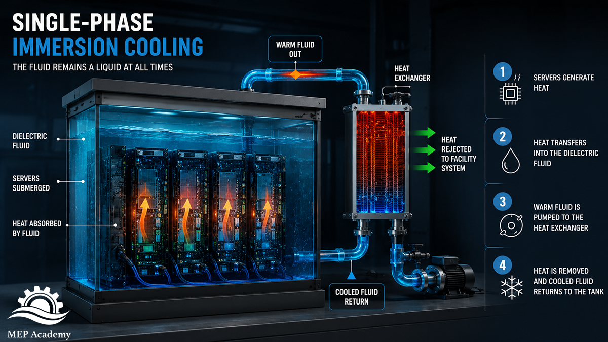
Single-Phase Immersion Cooling
Single-phase immersion cooling is currently the most widely deployed immersion cooling technology.
In a single-phase system, the dielectric fluid remains a liquid throughout the entire cooling process. It never boils or changes state.
Servers are mounted vertically inside a sealed immersion tank filled with dielectric fluid. As CPUs, GPUs, memory, and power electronics generate heat, that heat transfers directly into the surrounding liquid.
A circulation pump moves the warmed dielectric fluid through a heat exchanger, where heat is transferred into a separate facility water loop. The cooled dielectric fluid then returns to the immersion tank, creating a continuous closed-loop cooling cycle.
Because the fluid never changes phase, these systems are relatively straightforward to design, operate, and maintain.
Many manufacturers prefer this approach because it uses familiar pumping and heat exchanger technologies while still providing dramatically better cooling performance than conventional air cooling.
Insert Image Here
Figure 2.In a single-phase immersion cooling system, the dielectric fluid remains a liquid at all times while continuously circulating through a heat exchanger.
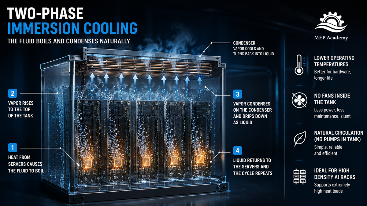
Two-Phase Immersion Cooling
Two-phase immersion cooling operates on an entirely different principle.
Instead of remaining a liquid, the dielectric fluid is intentionally selected to boil at relatively low temperatures.
As processors become hot, the surrounding dielectric fluid begins boiling directly on the electronic components.
This boiling process absorbs enormous amounts of heat.
The resulting vapor naturally rises toward the top of the immersion tank, where it contacts a condenser supplied with cooler facility water.
The vapor condenses back into liquid droplets that fall back into the tank, repeating the cycle continuously.
One interesting characteristic of two-phase immersion cooling is that no circulation pumps are required inside the immersion tank itself.
Gravity and phase change perform much of the work.
The process resembles a miniature water cycle:
Liquid absorbs heat.
Liquid boils.
Vapor rises.
Vapor condenses.
Liquid falls back into the tank.
The cycle repeats continuously.
Although two-phase systems offer exceptional heat transfer capabilities, they generally require more specialized fluids and carefully engineered containment systems, making them more complex than single-phase designs.
Insert Image Here
Figure 3.Two-phase immersion cooling uses the boiling and condensation of a dielectric fluid to transfer heat away from high-performance computing equipment.
Single-Phase vs. Two-Phase Comparison
Feature
Single-Phase
Two-Phase
Dielectric fluid remains liquid
✔ Yes
✘ No
Fluid boils during operation
✘ No
✔ Yes
Internal circulation pump required
✔ Yes
Usually No
Uses condenser inside tank
✘ No
✔ Yes
System complexity
Lower
Higher
Maintenance complexity
Lower
Higher
Typical applications
AI, HPC, enterprise data centers
Extremely high-density AI and research computing
Technology maturity
More common today
Growing rapidly
Both technologies dramatically outperform traditional air cooling at high rack densities.
Which solution is selected depends on numerous factors including equipment compatibility, rack density, facility design, maintenance philosophy, operating costs, and owner preferences.
Why Artificial Intelligence Is Driving Immersion Cooling
Artificial intelligence is fundamentally changing the way data centers are designed.
For decades, most enterprise servers handled workloads such as databases, web hosting, email, virtualization, and business applications. These servers generated manageable amounts of heat, allowing traditional air-cooling systems to perform effectively.
AI workloads are different.
Training large language models, performing machine learning, rendering complex simulations, and executing scientific calculations require enormous numbers of Graphics Processing Units (GPUs) operating simultaneously.
Unlike traditional CPUs, modern GPUs can consume several hundred watts each, with the latest generations approaching or exceeding 1,000 watts per processor.
A single AI server may contain:
Multiple high-performance GPUs
High-speed memory
Multiple CPUs
High-capacity networking hardware
Large power supplies
When dozens of these servers are installed into one rack, power densities increase dramatically.
Instead of cooling a 10-kilowatt rack, engineers may now be cooling a rack exceeding 100 kilowatts—and in some next-generation AI deployments, over 200 kilowatts.
This creates several engineering challenges.
Traditional air cooling requires:
Larger CRAH or CRAC units
Higher airflow volumes
More fan power
Increased ductwork or air distribution
More careful airflow management
Greater building mechanical capacity
Eventually, simply moving more air becomes impractical.
Liquid cooling solves this problem by transporting heat much more efficiently.
Because liquids have significantly higher heat capacity than air, much smaller volumes can carry the same amount of thermal energy.
This allows AI processors to operate at much higher performance levels while maintaining acceptable operating temperatures.
For this reason, many of the world’s largest technology companies—including hyperscale cloud providers and AI developers—are investing billions of dollars in liquid cooling technologies, including immersion cooling and direct-to-chip cooling.
As AI continues to evolve, cooling technology must evolve with it.
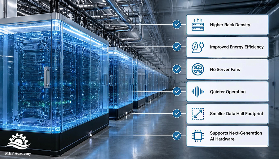
Advantages of Immersion Cooling
Immersion cooling offers numerous advantages over conventional air cooling, particularly for high-density computing applications.
Higher Rack Densities
Perhaps the greatest benefit is the ability to support significantly higher rack power densities.
Instead of being limited by airflow, immersion cooling removes heat directly from the electronic components, allowing much greater computing capacity within the same floor area.
The benefits of Immersion Cooling in Data Centers.
Improved Energy Efficiency
Traditional servers require thousands of high-speed fans that consume electricity around the clock.
Immersion-cooled servers often eliminate most or all internal server fans, reducing electrical consumption while simplifying airflow management.
This reduction in fan energy can improve overall facility efficiency.
Better Temperature Uniformity
Air-cooled servers can develop localized hot spots where airflow is restricted.
Immersion cooling surrounds every component with dielectric fluid, creating much more uniform cooling throughout the server.
This consistent thermal environment can improve reliability and performance.
Reduced Noise
One of the first things visitors notice inside an immersion-cooled data center is how quiet it is.
Traditional server rooms can exceed 80 decibels due to thousands of rapidly spinning fans.
Because immersion-cooled servers eliminate most internal fans, noise levels are dramatically reduced.
Smaller Air Infrastructure
Many conventional cooling components become less important when server heat is removed directly by liquid.
Facilities may require fewer:
Raised floor systems
Perforated floor tiles
Hot aisle containment systems
Cold aisle containment systems
Large air distribution pathways
Instead, the cooling infrastructure shifts toward liquid piping and heat exchangers.
Supports Future AI Hardware
Perhaps the greatest long-term advantage is scalability.
As AI processors continue increasing in power consumption, immersion cooling provides a practical path toward cooling the next generation of ultra-high-density computing hardware.
Disadvantages of Immersion Cooling
Although immersion cooling offers impressive benefits, it is not the ideal solution for every data center.
Like every engineering system, it involves tradeoffs.
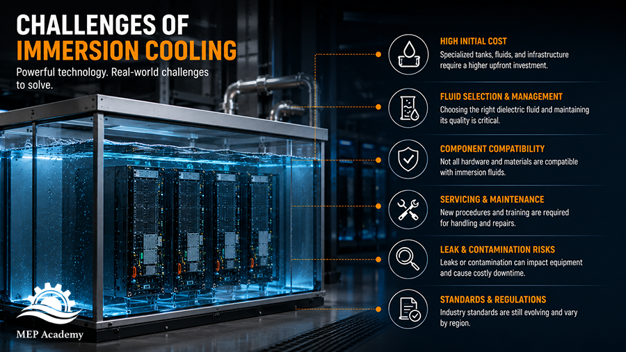
Higher Initial Cost
Immersion tanks, dielectric fluids, specialized infrastructure, and compatible hardware often require greater initial investment than conventional air-cooled systems.
However, many owners evaluate these costs over the facility’s entire operating life rather than considering only first cost.
Challenges of Immersion Cooling in Data Centers
Specialized Maintenance
Maintaining immersion-cooled servers differs from maintaining conventional servers.
Technicians must remove equipment from dielectric fluid, allow excess liquid to drain, and follow specialized maintenance procedures.
Personnel require additional training to safely service immersion systems.
Equipment Compatibility
Not every server is designed for immersion cooling.
Manufacturers may specify approved hardware configurations, compatible materials, and recommended dielectric fluids.
Compatibility should always be verified before deployment.
Fluid Management
Although dielectric fluids are engineered specifically for electronic cooling, they still require proper handling, storage, filtration, monitoring, and occasional replacement depending on the fluid chemistry and operating conditions.
Evolving Industry Standards
Immersion cooling remains a rapidly developing technology.
Industry standards, equipment designs, fluid chemistries, and maintenance practices continue to evolve as more AI facilities are built.
Organizations considering immersion cooling should carefully evaluate equipment vendors, long-term support, service availability, and future expansion plans.
Despite these challenges, industry experts generally expect liquid cooling technologies to play an increasingly important role as AI computing continues to grow.
Rather than replacing every air-cooled data center, immersion cooling is likely to become one of several specialized cooling strategies used where extremely high rack densities make conventional air cooling impractical.
Design Considerations for Engineers and Contractors
As immersion cooling becomes more common, the responsibilities of mechanical engineers, electrical engineers, contractors, commissioning agents, and facility owners are beginning to change. While the servers themselves may look dramatically different, the supporting infrastructure becomes even more important.
One of the biggest misconceptions is that immersion cooling eliminates the need for mechanical systems.
It does not.
It simply changes where heat is captured.
Instead of removing heat from room air, the mechanical system removes heat from a liquid loop. The same amount of heat must still leave the building because every watt of electrical energy consumed by the servers eventually becomes heat.
For engineers and contractors, this means designing and constructing a reliable heat rejection system becomes even more critical.
Mechanical System Design
Although immersion cooling reduces the need for large air-handling systems inside the data hall, the facility still requires robust mechanical infrastructure to reject heat outdoors.
Depending on the owner’s design criteria, this may include:
Chilled water systems
Cooling towers
Dry coolers
Fluid coolers
Plate-and-frame heat exchangers
Pumps and piping systems
Expansion tanks
Water treatment systems
Filtration equipment
Rather than designing airflow through a room, engineers are increasingly designing liquid distribution systems that move heat efficiently throughout the facility.
Piping Infrastructure
Liquid-cooled data centers contain considerably more piping than traditional air-cooled facilities.
Design considerations include:
Supply and return piping
Pump redundancy
Isolation valves
Balancing valves
Air elimination
Expansion control
Leak detection
Equipment isolation for maintenance
Future expansion capacity
Many AI facilities also incorporate redundant cooling loops so maintenance can occur without shutting down critical computing equipment.
Electrical Infrastructure
Although immersion cooling reduces fan energy within the servers, AI equipment still requires enormous amounts of electrical power.
Electrical engineers must consider:
Larger electrical services
Higher-capacity switchgear
UPS systems
Standby generators
Busways
Rack power distribution
Grounding systems
Monitoring equipment
The cooling method changes.
The electrical demand continues to grow.
Structural Considerations
Immersion cooling tanks are considerably heavier than conventional server racks.
Remember that each tank contains:
Servers
Steel framework
Heat exchangers
Hundreds or even thousands of pounds of dielectric fluid
Structural engineers must verify:
Floor loading
Equipment anchorage
Seismic restraints
Access pathways
Equipment replacement clearances
These loads can be substantially greater than traditional raised-floor server installations.
Maintenance Access
One design aspect that is sometimes overlooked is serviceability.
Engineers should provide adequate space for:
Opening tank lids
Removing server modules
Servicing pumps
Cleaning heat exchangers
Fluid filtration
Fluid replacement
Crane or lifting equipment where required
Just because the equipment is compact does not mean it requires less maintenance space.
Proper access remains essential throughout the life of the facility.
Commissioning Considerations
Commissioning becomes even more important with immersion cooling systems.
Testing may include:
Fluid circulation verification
Pump operation
Temperature monitoring
Flow verification
Leak testing
Heat exchanger performance
Control sequence verification
Alarm testing
Emergency shutdown procedures
Like any mission-critical infrastructure, successful startup depends on careful planning and comprehensive testing.
Common Misconceptions About Immersion Cooling
Because immersion cooling is relatively new to many people, several misconceptions continue to circulate.
Let’s clear up some of the most common ones.
Misconception #1: The Servers Are Underwater
This is probably the biggest misconception.
Servers are not submerged in water.
They operate inside specially engineered dielectric fluids that do not conduct electricity.
These fluids are specifically developed for cooling electronic equipment while providing electrical insulation.
Misconception #2: Immersion Cooling Eliminates HVAC Systems
Not even close.
The heat still has to leave the building.
Immersion cooling changes how heat is collected—not whether heat must be rejected.
Most immersion-cooled facilities still rely on cooling towers, dry coolers, fluid coolers, chilled water systems, pumps, heat exchangers, and sophisticated control systems.
Mechanical engineers remain an essential part of every immersion-cooled data center.
Misconception #3: The Entire Data Center Is Filled With Liquid
Only the servers are immersed.
The remainder of the facility still contains electrical rooms, UPS equipment, batteries, generators, switchgear, transformers, networking equipment, offices, maintenance areas, and numerous other support spaces.
Many of these areas continue using conventional HVAC systems.
Misconception #4: Immersion Cooling Is Replacing Every Data Center
Not necessarily.
Air cooling remains an excellent solution for many facilities.
Direct-to-chip cooling is also growing rapidly.
Future data centers will likely use multiple cooling strategies depending on rack density, application, owner preference, and total cost of ownership.
Immersion cooling is one important tool—not the only tool.
Misconception #5: There Are No Fans Anywhere
Although immersion-cooled servers often eliminate internal server fans, many facilities still use fans elsewhere.
Cooling towers, dry coolers, electrical equipment, generators, transformers, and HVAC systems frequently include fans.
The overall facility is quieter, but fans have certainly not disappeared entirely.
The Future of Immersion Cooling
Only a few years ago, immersion cooling was considered a niche technology used primarily in research laboratories and specialized high-performance computing facilities.
Today, the conversation has changed dramatically.
Artificial intelligence has accelerated demand for computing infrastructure at an unprecedented pace.
Every new generation of AI hardware produces more computing power.
More computing power consumes more electricity.
electricity generates more heat.
More heat requires better cooling technologies.
This cycle continues with every new generation of processors.
Industry analysts expect liquid cooling—including both immersion cooling and direct-to-chip cooling—to become increasingly common in hyperscale AI facilities over the next decade.
That does not necessarily mean traditional air-cooled data centers will disappear.
Instead, future facilities may use several different cooling technologies within the same campus.
For example:
Traditional enterprise servers may remain air cooled.
Medium-density AI clusters may use direct-to-chip cooling.
Ultra-high-density AI training clusters may use immersion cooling.
Each technology has strengths, and owners will select the approach that best fits their operational requirements.
One trend, however, appears increasingly clear.
Mechanical infrastructure will become more important—not less.
The future AI data center will likely contain:
Larger liquid distribution systems
More heat exchangers
More sophisticated controls
Increased monitoring
Greater redundancy
Higher-capacity heat rejection equipment
As computing evolves, so must the buildings that support it.
Key Takeaways
Immersion cooling represents one of the most significant changes in data center cooling technology in decades.
Rather than relying on air to remove heat from electronic equipment, immersion cooling places servers directly into a dielectric liquid capable of absorbing enormous amounts of thermal energy.
As artificial intelligence continues increasing rack power densities, this technology provides a practical method for cooling hardware that would be difficult—or even impossible—to cool efficiently with air alone.
The most important concepts to remember are:
Immersion cooling submerges servers in a non-conductive dielectric fluid—not water.
The dielectric fluid absorbs heat directly from the electronic components.
Heat is transferred through heat exchangers into the facility water system.
Mechanical systems still reject that heat outdoors using cooling towers, dry coolers, fluid coolers, or chilled water systems.
Single-phase systems circulate liquid dielectric fluid, while two-phase systems use boiling and condensation to transfer heat.
Immersion cooling supports much higher rack power densities than conventional air cooling.
Engineers, contractors, and facility owners must still design robust mechanical, electrical, structural, and control systems to support these installations.
As AI infrastructure continues expanding, immersion cooling is expected to become an increasingly important solution for high-density computing environments.
While immersion cooling may not replace every traditional data center, it is already reshaping how engineers think about cooling the next generation of artificial intelligence infrastructure. Understanding this technology today provides valuable insight into where the industry is headed tomorrow.
Frequently Asked Questions
What is immersion cooling?
Immersion cooling is a liquid cooling technology in which servers are completely submerged in a specially engineered dielectric fluid that does not conduct electricity. The fluid absorbs heat directly from electronic components and transfers that heat to the building’s mechanical cooling system through a heat exchanger. Unlike conventional air cooling, immersion cooling removes heat directly at the source rather than cooling the surrounding room air.
What is dielectric fluid?
Dielectric fluid is a specially formulated liquid designed for cooling electronic equipment. Unlike water, dielectric fluids do not conduct electricity, allowing powered electronic components to operate safely while submerged. These fluids also provide excellent thermal transfer characteristics, making them highly effective for removing heat from processors, GPUs, memory modules, and other electronic components.
Is immersion cooling better than air cooling?
Neither cooling method is universally better. Traditional air cooling remains an excellent solution for many enterprise data centers with moderate rack densities. Immersion cooling becomes increasingly attractive as rack power densities rise because liquid transfers heat much more efficiently than air. For very high-density AI computing, immersion cooling can often support higher performance while reducing airflow requirements and improving energy efficiency.
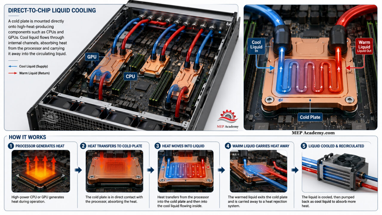
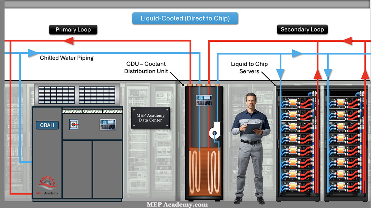
What is the difference between immersion cooling and direct-to-chip cooling?
The biggest difference is how the heat is removed. With immersion cooling, the entire server is submerged in dielectric fluid. With direct-to-chip cooling, cold plates are attached directly to high-heat components such as CPUs and GPUs, while much of the remaining server continues to be cooled by air. Both technologies are forms of liquid cooling, but they use different approaches to remove heat.
Does immersion cooling eliminate HVAC systems?
No. This is one of the most common misconceptions. Immersion cooling changes how heat is collected—not how it ultimately leaves the building. The heat must still be rejected outdoors using mechanical systems such as: Cooling towers Dry coolers Fluid coolers Chilled water systems Pumps Heat exchangers Mechanical infrastructure remains an essential part of every immersion-cooled facility.
Why doesn’t the liquid damage the servers?
Because immersion cooling uses dielectric fluids rather than water. Dielectric fluids are electrically non-conductive, meaning they do not create short circuits when they contact electronic components. The fluids are specifically engineered for electronic cooling applications.
Can any server be used for immersion cooling?
Not always. Although some standard server hardware can be adapted for immersion cooling, many manufacturers now offer equipment specifically designed or certified for immersion applications. Compatibility with materials, connectors, thermal interfaces, and fluid chemistry should always be confirmed before deployment.
Does immersion cooling eliminate server fans?
In many cases, yes. Because the dielectric fluid removes heat directly from the electronic components, immersion-cooled servers often do not require the high-speed internal fans found in traditional air-cooled servers. Removing these fans can reduce electrical consumption, decrease noise levels, and simplify server design. However, fans may still be used elsewhere in the facility, such as on cooling towers, dry coolers, generators, or other mechanical equipment.
Is immersion cooling used only for AI?
No. Although AI is currently driving much of the industry’s growth, immersion cooling has been used for years in: High-performance computing (HPC) Scientific research Cryptocurrency mining Government computing Defense applications Supercomputers Artificial intelligence has simply accelerated adoption because of its exceptionally high computing and cooling requirements.
Is immersion cooling safe?
Yes—when properly designed, installed, and maintained. Modern immersion cooling systems include engineered tanks, compatible dielectric fluids, monitoring systems, leak detection, filtration systems, temperature controls, and established maintenance procedures. Like any engineered mechanical system, safety depends on proper design, installation, commissioning, and operation.
Is immersion cooling more energy efficient?
It can be. By eliminating many server fans and reducing the amount of air that must be moved through the data hall, immersion cooling can lower cooling energy requirements. The actual efficiency improvements depend on the overall facility design, climate, operating conditions, and heat rejection system.
Will immersion cooling replace every data center?
Probably not. The future will likely include multiple cooling technologies working side by side. Many enterprise facilities will continue using traditional air cooling. Direct-to-chip cooling is expected to grow rapidly for AI workloads. Immersion cooling will likely be used where extremely high rack densities justify its advantages. The cooling technology selected will depend on the application’s performance requirements, cost, maintainability, and overall design objectives.
Why is immersion cooling becoming more popular now?
The primary reason is artificial intelligence. Modern AI processors generate far more heat than traditional enterprise servers. As rack power densities continue increasing, conventional air cooling becomes more difficult and expensive to scale. Immersion cooling provides an efficient method for removing large amounts of heat directly from the computing hardware, making it an increasingly attractive solution for next-generation AI data centers.
What should engineers and contractors know about immersion cooling?
Mechanical engineers, electrical engineers, contractors, and commissioning teams should understand that immersion cooling changes the cooling strategy but does not eliminate the need for robust infrastructure. Successful immersion-cooled data centers still require carefully designed: Mechanical cooling systems Heat rejection equipment Pumping systems Heat exchangers Electrical distribution Structural support Controls and monitoring Commissioning procedures Preventive maintenance programs As AI infrastructure expands, understanding liquid cooling technologies will become increasingly valuable for professionals involved in designing, constructing, and operating modern data centers.
Currently Published
How Data Centers Actually Work An overview of how modern data centers operate, explaining the critical electrical, mechanical, and IT infrastructure required to keep servers running 24/7.
How Data Center Electrical Systems Work Understand how data center electrical systems deliver continuous power using switchgear, UPS systems, generators, and redundancy design.
Data Center Refrigerant Economizer Discover how refrigerant economizer systems improve cooling efficiency by using outdoor conditions to reduce compressor operation and lower energy consumption.
How Data Center UPS Systems Work Understand how UPS systems provide instant backup power and protect data centers from outages and power disruptions.
Hot Aisle vs Cold Aisle Containment Hot aisle vs cold aisle containment explained. Learn how airflow control improves data center cooling efficiency and reduces energy costs.
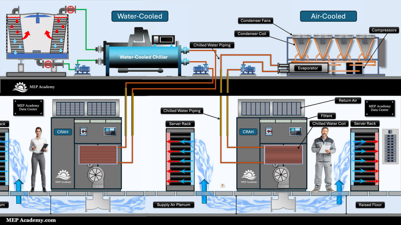
Data Center Chilled Water Systems Explained Learn how chilled water systems cool data centers, including chillers, CRAH units, pumps, and how the entire system removes heat efficiently.
CRAC vs CRAH Units Explained Learn the difference between Computer Room Air Conditioners and Computer Room Air Handlers, including how DX refrigerant cooling compares with chilled water cooling in data center environments.
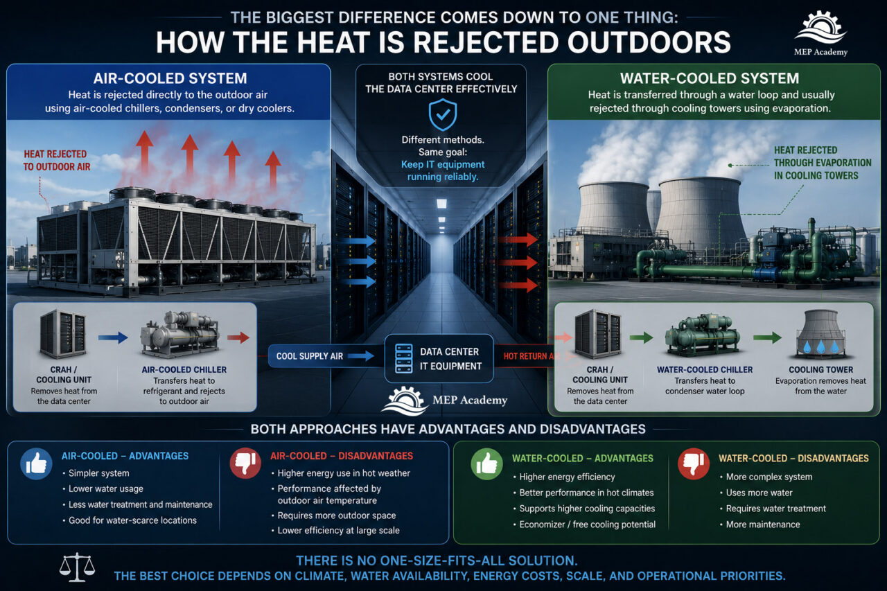
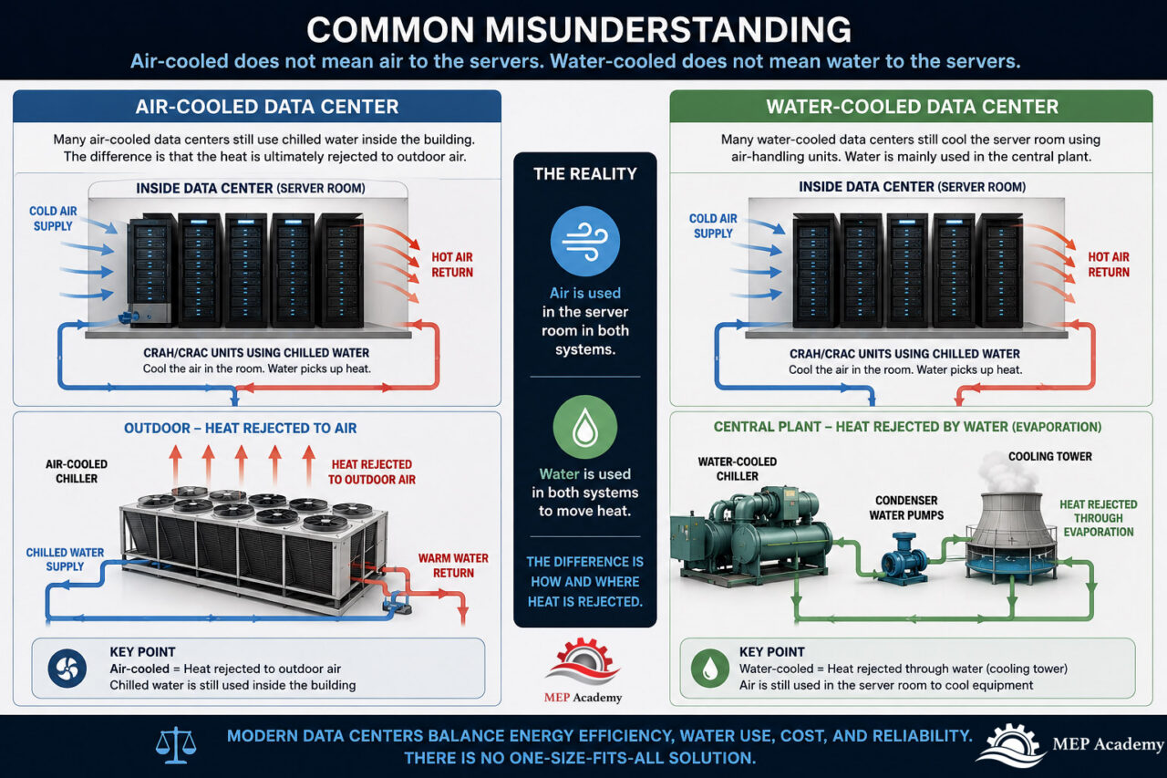
Air-Cooled vs Water-Cooled Data Centers Learn the difference between Computer Room Air Conditioners and Computer Room Air Handlers, including how DX refrigerant cooling compares with chilled water cooling in data center environments.
Immersion Cooling Explained Discover how immersion cooling is transforming AI data centers by submerging servers in a non-conductive dielectric fluid for highly efficient heat removal. Learn how single-phase and two-phase immersion cooling work, why AI is driving their adoption, and how these systems compare to traditional air cooling.
Many contractors avoid public works projects because they believe prevailing wage is too complicated, too risky, or simply not worth the effort.
The reality is that thousands of successful contractors perform prevailing wage work every day. The key difference is that they understand the rules before they submit their bid.
If you are an estimator, project manager, business owner, payroll administrator, or office manager, understanding prevailing wage is essential if you plan to work on government-funded construction projects.
One mistake can significantly impact profitability and potentially expose your company to penalties, back wages, or administrative headaches that could have been avoided during the bidding phase.
Fortunately, prevailing wage is not as complicated as many people think.
Once you understand a few core concepts, the process becomes much easier to manage.
In this guide, we’ll explain what prevailing wage is, how it affects contractors, where it applies, and what construction professionals need to know before pursuing public works projects.
This article is written specifically from a contractor’s perspective rather than a legal perspective.
Educational Disclaimer
This article is intended for educational purposes only and should not be considered legal, payroll, accounting, or labor compliance advice. Prevailing wage requirements vary by federal, state, and local jurisdictions and may change over time. Contractors should always verify current wage determinations, labor classifications, apprenticeship requirements, and compliance obligations with the governing agency and applicable regulations before bidding or performing work.
Prevailing Wage for Contractors Explained
Section 1: What Is Prevailing Wage?
At its most basic level, prevailing wage is a government-mandated minimum wage and benefit package that contractors must pay workers performing construction work on certain public projects.
The word “prevailing” refers to the wage rates that are determined to be common or standard for specific trades within a particular geographic area.
Prevailing wage rates are established by government agencies and vary based on several factors, including:
Geographic location
Type of construction
Labor classification
Scope of work
Applicable regulations
For example, an HVAC sheet metal worker in Los Angeles may have a significantly different prevailing wage rate than a sheet metal worker performing similar work in Sacramento.
Likewise, a plumber, electrician, controls technician, and sheet metal installer may all work on the same project but have completely different wage rates.
This is because prevailing wage is based on labor classifications rather than a single wage rate that applies to everyone.
What Does Prevailing Wage Include?
Many people mistakenly believe prevailing wage is simply a higher hourly wage.
It is actually much more than that.
Prevailing wage generally consists of two primary components:
Base Hourly Wage
This is the direct hourly compensation paid to the employee.
Fringe Benefits
These are additional benefits provided on behalf of the employee and may include:
Health insurance
Pension contributions
Vacation pay
Training contributions
Apprenticeship programs
Supplemental benefits
Contractors may satisfy fringe benefit requirements through approved benefit programs or, depending on applicable regulations, pay portions directly to the employee.
The specific requirements vary by jurisdiction.
Why Does Prevailing Wage Exist?
The purpose of prevailing wage laws is to prevent contractors from undercutting local labor markets by paying substantially lower wages on publicly funded projects.
The intent is to create a level playing field where contractors compete based on productivity, experience, quality, and project execution rather than by simply paying workers less.
Whether contractors agree or disagree with prevailing wage laws, understanding them is essential because compliance is generally mandatory on applicable projects.
Think of It This Way
Imagine two HVAC contractors bidding on the same public school modernization project.
Without prevailing wage requirements, one contractor might pay technicians $45 per hour while another pays $25 per hour.
The contractor with lower labor costs could gain a substantial pricing advantage regardless of experience or qualifications.
Prevailing wage regulations attempt to standardize labor costs so contractors compete on factors such as:
Productivity
Scheduling
Project management
Safety performance
Prefabrication capabilities
Experience
Quality of installation
Why Contractors Must Understand Prevailing Wage Before They Bid
Many contractors get into trouble before construction even begins.
The mistake often occurs during estimating.
A contractor who accidentally prices a prevailing wage project using standard private-sector labor rates can underbid the project by tens or even hundreds of thousands of dollars.
That’s why understanding prevailing wage is not simply a payroll issue.
It is an estimating issue.
It is a project management issue.
It is an operations issue.
And ultimately, it is a profitability issue.
The earlier your team identifies a project as prevailing wage, the better positioned your company will be to bid it accurately and execute it successfully.
Section 2: Who Should Understand Prevailing Wage Within a Construction Company?
One of the biggest misconceptions surrounding prevailing wage is that only payroll personnel need to understand it.
That is simply not true.
Successful contractors treat prevailing wage as a company-wide responsibility.
In many organizations, multiple departments contribute to the overall success of a prevailing wage project.
When everyone understands their role, projects tend to run much more smoothly.
When departments operate independently, mistakes become much more likely.
Let’s look at who should be involved.
Company Owners and Executives
Owners and executives make many of the strategic decisions that determine whether public works projects fit the company’s long-term goals.
They should understand:
The opportunities associated with public works projects
The additional administrative requirements
Internal staffing needs
Compliance responsibilities
Resource planning requirements
Leadership ultimately determines whether the company will pursue these opportunities.
Estimators
Estimators are often the first line of defense.
Their responsibilities may include:
Identifying prevailing wage requirements
Reviewing bid documents
Verifying labor classifications
Identifying compliance requirements
Budgeting administrative costs
Many prevailing wage mistakes originate during estimating.
Early identification is critical.
Project Managers
Project managers help coordinate compliance throughout the life of the project.
Their responsibilities may include:
Managing documentation
Coordinating with labor compliance personnel
Communicating with project stakeholders
Supporting internal teams
Project managers often become the central communication hub.
Payroll and Accounting Personnel
Payroll departments play an extremely important role.
Their responsibilities may include:
Processing payroll
Preparing certified payroll reports
Verifying wage rates
Maintaining records
Accounting departments may also assist with project administration and financial reporting.
Human Resources Personnel
Some companies involve human resources as part of the compliance process.
Responsibilities may include:
Employee records
Training documentation
Apprenticeship information
Benefit records
Their involvement often depends on company size.
Field Superintendents and Foremen
Field supervisors are a critical piece of the process.
They often have the most direct visibility into daily labor activities.
Responsibilities may include:
Assigning labor
Tracking employee activities
Supporting labor classifications
Verifying labor hours
Accurate field information helps everyone downstream.
Administrative Support Staff
Administrative personnel frequently help maintain project documentation.
They may assist with:
Organizing reports
Maintaining project records
Tracking documentation deadlines
Coordinating internal communication
Although they often work behind the scenes, their contributions can be extremely valuable.
Estimator Tip #1: Create a Responsibility Matrix
Before your company begins pursuing public works projects, create a simple responsibility matrix.
Ask one question.
Who owns each task?
Examples:
Task
Responsible Party
Identify prevailing wage requirements
Estimator
Verify labor classifications
Estimator
Coordinate project turnover
Project Manager
Track labor assignments
Superintendent
Prepare certified payroll
Payroll
Maintain documentation
Administration
The objective is to eliminate assumptions.
When responsibilities are clearly assigned, projects tend to operate much more efficiently.
Prevailing Wage Is a Team Sport
Contractors who struggle with prevailing wage often place the entire burden on one employee.
That approach rarely works long term.
The contractors who become successful with public works projects understand that prevailing wage is not a payroll issue, an estimating issue, or a project management issue.
It is all of those things simultaneously.
The earlier your company adopts a team-based approach, the easier prevailing wage projects become to manage.
Section 3: Which Projects Require Prevailing Wage?
One of the biggest misconceptions contractors have is assuming every government project automatically requires prevailing wage.
That is not always true.
Likewise, many contractors assume private projects are exempt from prevailing wage requirements, which is also not always true.
The answer often depends on who is funding the project, who owns the project, and the specific laws that apply in that jurisdiction.
This is why contractors should never assume whether prevailing wage applies. They should verify it before preparing their estimate.
Public Works Projects Commonly Subject to Prevailing Wage
Prevailing wage requirements are most commonly associated with public works projects.
Examples may include:
Public schools
Colleges and universities
Government office buildings
Courthouses
Libraries
Airports
Fire stations
Police stations
Water treatment facilities
Wastewater treatment plants
Transportation infrastructure
Public housing projects
Municipal facilities
For MEP contractors, many projects involving school districts, municipalities, counties, state agencies, and public utility providers will likely require prevailing wage compliance.
Private Projects Can Sometimes Trigger Prevailing Wage Requirements
This is where some contractors get surprised.
Certain privately owned projects may still require prevailing wage if they receive government funding, tax incentives, grants, or other public financial assistance.
Depending on the state, this could include:
Affordable housing projects
Renewable energy projects
Certain healthcare facilities
Public-private partnerships
Economic development projects
This is why contractors should never assume that private ownership automatically means prevailing wage does not apply.
How Can Contractors Tell if a Project Requires Prevailing Wage?
Fortunately, there are usually clues throughout the bidding documents.
Review the following documents carefully:
Request for Proposal (RFP)
The RFP often states whether prevailing wage applies.
Look for language such as:
This project is subject to prevailing wage requirements.
Contractors shall comply with all applicable labor laws.
Certified payroll reporting is required.
Applicable wage determinations shall be used.
Instructions to Bidders
Many public entities include prevailing wage requirements in the bidding instructions.
Do not skip this section.
Estimators often focus immediately on the drawings and specifications while overlooking important administrative requirements.
Project Specifications
Review Division 00 and Division 01 carefully.
Prevailing wage requirements are often buried within these sections.
Look for references to:
Labor compliance
Certified payroll
Wage determinations
Apprenticeship requirements
Reporting obligations
Contract Documents
Contract agreements frequently contain additional requirements that may not appear elsewhere.
Never assume that because the drawings don’t mention prevailing wage, it does not apply.
Red Flags That Should Immediately Get Your Attention
If you see any of the following terms, slow down and investigate further:
Public Works
Prevailing Wage
Certified Payroll
DIR Registration
Labor Compliance Program
Davis-Bacon Act
Project Labor Agreement (PLA)
Apprenticeship Requirements
Funding Agency Requirements
These terms often indicate additional labor compliance obligations.
Federal vs State Prevailing Wage Programs
Contractors may encounter both federal and state prevailing wage requirements.
Federal Projects
Federal projects are commonly governed by the Davis-Bacon Act.
This law establishes prevailing wage requirements for certain federally funded construction projects.
State Projects
Many states have their own prevailing wage laws that operate independently of federal regulations.
The rules may vary significantly between states.
Areas that may differ include:
Wage rates
Threshold amounts
Reporting requirements
Apprenticeship obligations
Contractor registration requirements
Penalties for non-compliance
Contractors working in multiple states should never assume the rules are the same everywhere.
What If a Project Contains Both Federal and State Funding?
Some projects may involve multiple funding sources.
In these situations, additional complexity can arise because more than one set of regulations may apply.
Contractors should identify this early during the bidding phase rather than after construction begins.
Questions should be resolved before submitting a proposal whenever possible.
Build a Simple Verification Habit
Before beginning any estimate, ask these five questions:
Who owns the project?
Who is funding the project?
Does the RFP mention prevailing wage?
Are certified payroll reports required?
Are there apprenticeship or labor compliance requirements?
If any answer is yes, stop and investigate further before building your labor costs.
A five-minute review at the beginning of the estimate can prevent expensive mistakes later.
Remember, prevailing wage is not something you discover after winning the project.
It is something you identify before you submit your bid.
Section 4: Why Prevailing Wage Matters to Estimators
Many contractors mistakenly view prevailing wage as a payroll issue.
It isn’t.
Prevailing wage begins as an estimating issue long before payroll ever gets involved.
By the time payroll discovers a labor compliance problem, the contractor has already won the project, signed a contract, mobilized labor, and committed to performing the work.
At that point, it’s often too late to fix the mistake without absorbing significant financial losses.
This is why estimators play such a critical role in prevailing wage projects.
The estimator is usually the first person within the company who determines whether the project will be profitable or problematic.
Labor Is Often Your Largest Cost
For many MEP contractors, labor is one of the largest components of the estimate.
If labor is incorrectly calculated, the entire estimate can be compromised.
Consider a contractor bidding an HVAC replacement project at a public school.
If the estimator accidentally uses standard commercial labor rates instead of prevailing wage labor rates, the error can be substantial.
Let’s look at a simplified example.
Non-Prevailing Wage Estimate
500 sheet metal labor hours
$75 per hour burdened labor rate
Total labor cost:
500 × $75 = $37,500
Prevailing Wage Estimate
500 sheet metal labor hours
$125 per hour burdened labor rate
Total labor cost:
500 × $125 = $62,500
Difference:
$25,000
This is before considering any additional administrative costs.
Now imagine a project with several trades involved.
Sheet metal
HVAC piping
Plumbing
Electrical
Controls
The difference can quickly become six figures.
Prevailing Wage Impacts More Than Hourly Rates
Another common mistake is assuming you simply substitute one labor rate for another.
Unfortunately, it is rarely that simple.
Prevailing wage projects often carry additional costs that estimators should consider.
Examples include:
Certified Payroll Administration
Someone within the company must prepare and submit certified payroll reports.
This may require:
Payroll staff
Accounting staff
Administrative staff
Third-party labor compliance consultants
Apprenticeship Requirements
Some jurisdictions require specific apprentice participation ratios.
Failing to meet these requirements can create compliance issues.
Additional Documentation
Projects may require additional recordkeeping such as:
Employee classifications
Daily labor tracking
Payroll reporting
Fringe benefit documentation
Training verification
Increased Project Administration
Project managers may spend additional time handling:
Labor compliance questions
Agency audits
Documentation requests
Contractor coordination
All of these activities cost money.
If they are not included in the estimate, they eventually become overhead expenses that reduce profitability.
Estimator Tip #2: Create a Prevailing Wage Checklist
Don’t rely on memory.
Develop a standardized checklist that you review before every public works estimate.
One of the best practices many experienced estimators use is creating a separate estimate category called:
Prevailing Wage Compliance
This category allows the estimator to capture costs that might otherwise be forgotten.
Examples may include:
Certified payroll administration
Labor compliance consultants
Additional project management hours
Administrative support
Training requirements
Documentation requirements
Separating these costs also provides visibility during estimate reviews.
Instead of burying them in overhead, they become intentional cost decisions.
Your Estimating Process Should Change
Many contractors use the same estimating process for every project.
That approach can create problems.
Private commercial projects and prevailing wage projects should not be estimated exactly the same way.
Prevailing wage projects often require additional review steps.
For example:
Typical Private Project Workflow
Review drawings.
Perform takeoff.
Build labor.
Build material pricing.
Price equipment.
Add overhead and profit.
Submit proposal.
Typical Prevailing Wage Workflow
Review RFP.
Verify prevailing wage requirements.
Review labor compliance requirements.
Verify wage determinations.
Perform takeoff.
Build labor.
Price administrative costs.
Price compliance costs.
Review documentation requirements.
Add overhead and profit.
Submit proposal.
Notice that several additional steps occur before labor pricing even begins.
Skipping those steps can create expensive problems later.
Estimating Mistakes Are Difficult to Recover From
If material pricing changes after award, contractors can sometimes negotiate substitutions.
If equipment lead times change, schedules may be adjusted.
But if prevailing wage labor was underestimated, there are often very few options available.
The contractor is typically obligated to pay the required wage rates regardless of what was originally included in the estimate.
That’s why prevailing wage should never be viewed as simply a payroll function.
Successful contractors recognize that prevailing wage begins at the estimating desk.
The earlier your team identifies the requirements, the more accurate your estimate will be and the more profitable your project can become.
Section 5: Understanding Certified Payroll and Compliance Requirements
For many contractors, certified payroll is the part of prevailing wage that feels intimidating.
It is also one of the reasons some companies avoid public works projects altogether.
The good news is that certified payroll is manageable once you understand the process and build systems around it.
The key is to recognize that certified payroll is not an optional administrative task.
It is a contractual obligation on many prevailing wage projects.
What Is Certified Payroll?
Certified payroll is a weekly reporting process that documents who worked on the project, the work they performed, and how they were compensated.
The purpose is to demonstrate that contractors are complying with prevailing wage requirements.
Depending on the project and jurisdiction, contractors may be required to submit certified payroll reports to:
The project owner
A labor compliance agency
A state labor department
A third-party compliance administrator
An online reporting portal
The reporting process may vary, but the overall objective remains the same.
Contractors must be able to prove they are paying workers correctly.
Information Typically Included in Certified Payroll Reports
Although requirements vary, reports often include information such as:
Employee name
Worker identification information
Labor classification
Hours worked
Straight-time hours
Overtime hours
Wage rates paid
Fringe benefits paid
Gross wages
Net wages
Accuracy is extremely important.
Small errors can create significant administrative problems if they occur repeatedly throughout the project.
Why Labor Classifications Matter
One of the most common compliance issues involves labor classifications.
Workers must generally be paid according to the type of work they are actually performing.
For example, on an MEP project you may have several classifications involved, including:
Sheet metal workers
Plumbers
Pipefitters
Electricians
Controls technicians
Insulators
Each classification may have different wage rates and requirements.
Contractors should avoid assuming that one labor classification applies to all employees working on the project.
When in doubt, seek clarification before work begins.
Documentation Becomes Extremely Important
Private projects often allow contractors more flexibility in how they track labor.
Prevailing wage projects require much more discipline.
Good documentation protects the contractor.
Many successful contractors establish procedures for collecting information daily rather than trying to recreate it at the end of the week.
Examples of information that should be tracked include:
Employee start times
Employee finish times
Project locations
Work performed
Labor classifications used
Overtime hours
Apprentice participation
Waiting until Friday afternoon to reconstruct the entire week often leads to mistakes.
Who Should Manage Compliance?
One mistake smaller contractors often make is assuming one person can simply absorb all the additional work.
That approach can quickly become overwhelming.
Many contractors designate specific responsibilities.
For example:
Estimator
Identifies prevailing wage requirements during bidding.
Identifies labor compliance costs.
Flags project requirements.
Project Manager
Oversees project execution.
Coordinates documentation.
Manages compliance communication.
Payroll Administrator
Processes payroll.
Prepares certified payroll reports.
Verifies wage rates.
Field Supervisor
Tracks labor classifications.
Verifies daily work assignments.
Assists with documentation.
Creating a team approach often produces much better results than assigning everything to one individual.
Estimator Tip #3: Don’t Hide Compliance Costs Inside Overhead
Many estimators simply bury prevailing wage administration inside overhead percentages.
This can create two problems.
First, it hides the true cost of performing prevailing wage work.
Second, it makes future estimates more difficult to benchmark.
Instead, consider creating specific estimate line items such as:
Certified payroll administration
Labor compliance consultant
Additional project management hours
Administrative support hours
Visible costs are easier to track and improve over time.
What Happens If Mistakes Occur?
The consequences vary depending on the jurisdiction and severity of the issue.
Potential outcomes may include:
Back wage payments
Administrative penalties
Withheld project payments
Increased audits
Additional reporting requirements
Project delays
The purpose of mentioning these risks is not to create fear.
The purpose is to emphasize preparation.
Companies that establish good systems early often find prevailing wage projects become routine over time.
Treat Prevailing Wage as a Business Process
The most successful contractors do not treat prevailing wage as an occasional exception.
They treat it as a repeatable business process.
Once procedures are established, responsibilities are assigned, and documentation systems are in place, prevailing wage projects become much more manageable.
In many cases, contractors eventually become very comfortable pursuing public works opportunities because they have developed internal systems that their competitors may not have.
In other words, what initially feels like a burden can eventually become a competitive advantage.
Section 6: 10 Hidden Prevailing Wage Costs Contractors Often Forget to Include in Their Estimate
Many contractors understand that prevailing wage increases labor costs.
What they often underestimate are all the secondary costs that accompany prevailing wage projects.
These costs don’t always appear on the drawings.
They may not be shown in the specifications.
In many cases, they are hidden within administrative requirements that are easy to overlook during the bidding process.
Over time, these forgotten expenses can significantly impact project profitability.
Let’s look at ten of the most commonly overlooked costs.
1. Certified Payroll Administration
Certified payroll takes time.
Someone within the organization must gather information, prepare reports, verify accuracy, and submit documentation.
Even with software, this process requires labor hours.
Ask yourself:
Who will perform this work?
Payroll administrator
Accounting staff
Human resources
Project coordinator
Third-party consultant
These costs should not be assumed to be free.
2. Labor Compliance Consultants
Some contractors hire outside firms to assist with compliance.
These consultants may help with:
Certified payroll
Labor classifications
Reporting requirements
Audit preparation
Documentation management
Their fees should be included in the estimate when applicable.
3. Additional Project Management Hours
Prevailing wage projects often require more communication than private projects.
Project managers may spend additional time on:
Documentation requests
Labor compliance questions
Agency coordination
Internal meetings
Employee classification issues
Those additional hours have value and should be budgeted accordingly.
4. Administrative Support Time
Someone must organize and maintain project records.
Examples include:
Employee records
Wage determinations
Apprenticeship documentation
Labor reports
Project correspondence
These tasks consume administrative resources.
If not estimated properly, they become unrecoverable overhead expenses.
5. Apprentice Program Requirements
Some projects require contractors to utilize apprentices according to established ratios.
There may also be training fund contributions or reporting obligations.
Failure to comply can create administrative problems and additional costs.
Contractors should verify these requirements before submitting their bids.
6. Additional Field Supervision
Field supervisors may spend additional time documenting labor activities.
Examples include:
Tracking employee assignments
Verifying labor classifications
Reviewing labor hours
Supporting payroll documentation
These responsibilities consume time that should be accounted for.
7. Labor Compliance Software
Many contractors invest in software platforms that help automate compliance processes.
These costs may include:
Monthly subscriptions
User licenses
Employee training
Software implementation
If the project is expected to utilize these tools, the cost should be considered.
8. Audit Preparation Time
Public works projects may be subject to audits.
Preparing for audits takes time.
Documentation may need to be gathered, reviewed, organized, and submitted.
Even if an audit never occurs, maintaining proper records requires effort throughout the project.
9. Additional Estimating Time
Prevailing wage projects often require more pre-bid analysis.
Estimators may spend additional time:
Reviewing wage determinations
Verifying labor classifications
Reviewing labor compliance requirements
Identifying administrative obligations
This extra effort should be recognized internally.
10. Employee Training and Internal Procedures
Prevailing wage projects often require internal training.
Employees may need instruction on:
Labor classifications
Time tracking procedures
Documentation requirements
Reporting expectations
Investing in training early can significantly reduce mistakes later.
Estimator Tip #4: Add a “Prevailing Wage Compliance” Category to Your Estimate
Many contractors hide these costs inside overhead.
That approach makes them difficult to measure.
Instead, create a dedicated estimate category called:
Prevailing Wage Compliance
Examples may include:
Item
Estimated Hours
Cost
Certified payroll administration
20 hours
$1,200
Project management administration
16 hours
$1,600
Administrative support
12 hours
$600
Labor compliance consultant
Lump sum
$2,500
Internal training
8 hours
$800
The actual numbers will vary by contractor and project size.
The objective is simply to make these costs visible.
Small Projects Are Often Affected the Most
Ironically, smaller projects can sometimes be impacted more significantly.
For example, a $200,000 HVAC replacement project may still require many of the same administrative activities as a $5 million project.
The fixed administrative costs become a larger percentage of the overall contract value.
This is one reason contractors occasionally discover that small public works projects generate lower profit margins than expected.
Think Beyond Labor Rates
When many contractors hear the term prevailing wage, they immediately think of hourly wages.
Experienced contractors think much bigger.
They think about the entire process.
Successful contractors estimate the labor.
Great contractors estimate the labor and the administrative systems required to support it.
That mindset often separates profitable public works contractors from those who eventually decide public work is too difficult to pursue.
Section 7: Common Prevailing Wage Mistakes Contractors Make
Many contractors don’t struggle with prevailing wage because the requirements are impossible to understand.
They struggle because several small mistakes compound throughout the life of a project.
In many companies, estimating, project management, payroll, accounting, and field operations all function independently.
When information is not properly transferred between departments, prevailing wage issues begin to appear.
The good news is that most of these mistakes are preventable.
Let’s examine some of the most common ones.
Mistake #1: Assuming Prevailing Wage Is Only a Payroll Responsibility
This is probably the most common mistake contractors make.
By the time payroll becomes involved, the estimate has already been completed and the project has often already been awarded.
Prevailing wage is not solely a payroll responsibility.
It is a company-wide responsibility.
It touches:
Estimating
Project management
Payroll
Accounting
Human resources
Field operations
Every department must understand its role.
Mistake #2: Using the Wrong Labor Rates During Estimating
This mistake can destroy project profitability before construction even begins.
Examples include:
Using standard commercial labor rates
Using outdated prevailing wage rates
Applying the wrong labor classification
Using rates from another county or jurisdiction
Labor rates should always be verified before the estimate is finalized.
Never assume the rates from a previous project are still valid.
Mistake #3: Failing to Review the Entire Bid Package
Some contractors immediately open the drawings and begin their takeoff.
That can create problems.
Prevailing wage requirements are often found within:
RFP documents
Instructions to bidders
Division 00 specifications
Division 01 specifications
Contract documents
If those documents are skipped, critical information can be missed.
Mistake #4: Not Including Administrative Costs in the Estimate
Contractors often estimate the field labor but forget the office labor.
Administrative costs may include:
Certified payroll preparation
Compliance tracking
Additional project management
Administrative support
Audit preparation
These costs should be intentionally estimated rather than absorbed into general overhead.
Mistake #5: Poor Department Handoffs
This issue occurs more frequently than many contractors realize.
Imagine this scenario.
The Estimator Knows
The estimator identifies that the project requires prevailing wage.
The Project Manager Doesn’t Know
The estimator fails to communicate the requirements during turnover.
The Superintendent Doesn’t Know
The superintendent assigns workers without understanding labor classifications.
Payroll Doesn’t Know
Payroll receives inaccurate information and processes payroll incorrectly.
Suddenly, a problem that could have been prevented during estimating becomes a company-wide issue.
Establish a Project Turnover Meeting
One of the simplest solutions is to implement a prevailing wage turnover meeting immediately after project award.
Participants may include:
Estimator
Project manager
Superintendent
Payroll administrator
Accounting representative
Review items such as:
Prevailing wage requirements
Labor classifications
Certified payroll requirements
Apprenticeship requirements
Administrative responsibilities
A 30-minute meeting can prevent months of frustration.
Estimator Tip #5: Create a Prevailing Wage Handoff Form
Develop a one-page handoff form that travels with every prevailing wage project.
The form may include:
Project Information
Project name
Project owner
Funding source
Project location
Compliance Requirements
☐ Prevailing wage required
☐ Certified payroll required
☐ Apprenticeship requirements apply
☐ Labor compliance consultant required
☐ Additional administrative support required
Internal Responsibilities
Estimator: __________________
Project Manager: __________________
Payroll Administrator: __________________
Field Superintendent: __________________
A simple document can dramatically improve communication between departments.
Mistake #6: Waiting Until the End of the Week to Track Labor
This creates unnecessary risk.
People forget details.
Hours become estimates.
Labor classifications become assumptions.
Instead, labor information should be documented daily.
Successful contractors build this process into their normal operations.
Mistake #7: Assuming Every Public Project Is the Same
This is another costly mistake.
Every project may have unique requirements.
Areas that can vary include:
Wage determinations
Reporting procedures
Funding agencies
Apprenticeship obligations
Documentation requirements
Treat every project as a new project.
Never rely entirely on previous experiences.
Mistake #8: Viewing Compliance as a Burden Instead of a System
Companies that struggle with prevailing wage often view it as extra work.
Companies that succeed with prevailing wage build systems around it.
The systems eventually become routine.
The procedures become repeatable.
And over time, those systems can become a competitive advantage.
Many contractors eventually discover that prevailing wage projects are not necessarily more difficult.
They are simply more structured.
The contractors who embrace that structure often become very successful in the public works market.
Section 8: How to Build a Prevailing Wage Estimating Process (Step-by-Step)
Successful contractors do not reinvent the wheel every time they bid a prevailing wage project.
They create a repeatable process.
The process may vary from company to company, but the overall objective remains the same.
Remove assumptions and replace them with procedures.
A standardized process helps contractors estimate projects more accurately, communicate expectations internally, and reduce the likelihood of costly mistakes.
The following eight-step process can serve as a framework for many contractors.
Before performing any takeoff, determine if prevailing wage applies.
Review the:
RFP
Instructions to bidders
Division 00 specifications
Division 01 specifications
Contract documents
Do not wait until later in the estimate.
This should be one of the first decisions you make.
If prevailing wage applies, flag the estimate immediately.
Some contractors even place a large notation at the top of the estimate that says:
PREVAILING WAGE PROJECT
That simple reminder can prevent errors throughout the estimating process.
Step 2: Identify Applicable Labor Classifications
Determine which trades will be involved.
Examples may include:
Sheet metal workers
HVAC pipefitters
Plumbers
Electricians
Controls technicians
Insulators
Test and balance technicians
Each trade may have different wage rates and requirements.
Never assume one labor classification applies to all workers.
Step 3: Verify Wage Determinations
Do not rely on previous estimates.
Verify current wage determinations for the project.
Questions to answer include:
What county applies?
What trade classifications apply?
What rates are currently in effect?
Are there future rate increases scheduled?
Build your estimate using verified information.
Step 4: Identify Compliance Requirements
Determine all administrative obligations.
Questions to ask include:
Is certified payroll required?
Are apprenticeship requirements applicable?
Is labor compliance monitoring required?
Is a third-party consultant involved?
Are additional reports required?
Capture these items early.
Step 5: Build Your Labor Costs
Now you can begin building your labor estimate.
This includes:
Labor hours
Burdened labor rates
Overtime assumptions
Shift work assumptions
Crew composition
Many contractors already have excellent labor production systems.
The key is ensuring they are built on the correct wage structure.
Step 6: Add Compliance Costs as Separate Line Items
Do not bury these costs inside overhead.
Examples may include:
Certified payroll administration
Project management administration
Labor compliance consultant
Additional accounting support
Administrative support hours
Visibility improves accountability.
Step 7: Conduct an Internal Review
Before submitting the estimate, perform a compliance review.
Ask:
Did we verify prevailing wage requirements?
Did we verify labor classifications?
Did we capture administrative costs?
Did we identify all reporting requirements?
This final review may only take a few minutes.
Those few minutes can prevent expensive mistakes.
Step 8: Prepare for Project Turnover
The estimating process should not end when the bid is submitted.
Prepare information that will eventually be transferred to the project team.
Identify:
Prevailing wage requirements
Labor classifications
Reporting requirements
Administrative responsibilities
A smooth transition from estimating to operations is critical.
California Contractor Spotlight: Understanding DIR Registration
California contractors have an additional requirement that deserves special attention.
Many California public works projects require contractors to register with the California Department of Industrial Relations (DIR).
This requirement generally applies before bidding or performing work on applicable public works projects.
Contractors should verify current requirements before pursuing public work.
Items to verify may include:
Contractor registration status
Subcontractor registration status
Certified payroll reporting requirements
Applicable labor compliance obligations
California contractors should never wait until after award to verify registration requirements.
This should become part of their normal estimating workflow.
Estimator Tip #6: Add a Prevailing Wage Header to Every Estimate
Create a section at the top of your estimate that looks something like this.
Prevailing Wage Review
Project Type: ___________________
Prevailing Wage Required: Yes / No
Funding Source: ___________________
Certified Payroll Required: Yes / No
Apprenticeship Requirements: Yes / No
Labor Compliance Consultant Required: Yes / No
Additional Administrative Hours: _______
Internal Compliance Review Completed: Yes / No
This information should remain visible throughout the estimate.
Do not bury it several tabs deep inside a spreadsheet.
Build Systems, Not Heroics
Many contractors survive prevailing wage projects by relying on one experienced employee who knows how everything works.
That strategy is risky.
What happens if that person is unavailable?
Successful companies build systems that everyone can follow.
The goal is not to depend on one individual.
The goal is to create a repeatable process that the entire organization understands.
When systems replace assumptions, prevailing wage projects become much easier to manage.
Section 9: Should Contractors Pursue Prevailing Wage Projects?
This is one of the most common questions contractors ask.
Is pursuing prevailing wage work worth it?
The answer depends entirely on your company’s goals, resources, and internal systems.
For some contractors, public works projects become a major part of their business strategy.
For others, private commercial work remains a better fit.
Neither approach is inherently right or wrong.
The key is making an informed business decision.
The Advantages of Pursuing Prevailing Wage Projects
Many contractors build extremely successful businesses around public works projects.
Some of the advantages include:
Consistent Project Opportunities
Government agencies continuously invest in infrastructure improvements.
Examples include:
Schools
Universities
Hospitals
Municipal buildings
Airports
Water treatment facilities
Public infrastructure
These projects often provide a steady source of bidding opportunities.
Larger Project Portfolios
Some public projects can be quite substantial.
Contractors may find opportunities to build long-term relationships with:
School districts
Municipalities
Universities
Utility agencies
Government organizations
Those relationships can create repeat business opportunities.
Reduced Price Competition in Some Markets
Not every contractor is willing to pursue prevailing wage work.
Some companies intentionally avoid public works projects because of the additional administrative requirements.
Contractors who develop efficient systems may find themselves competing against fewer qualified bidders.
Improved Internal Processes
Public works projects often force contractors to become more organized.
Many companies discover that the systems they develop for prevailing wage projects improve their private-sector operations as well.
Examples include:
Better documentation
Better communication
Better labor tracking
Better project turnover procedures
Better estimating processes
The organizational benefits sometimes extend far beyond public works projects.
The Challenges Contractors Must Consider
Prevailing wage projects also come with additional responsibilities.
Companies should be prepared for:
Increased Administrative Work
Prevailing wage projects often require additional effort from:
Payroll
Accounting
Project management
Field supervision
Administrative staff
This work must be planned and supported.
Additional Compliance Requirements
Contractors may encounter:
Certified payroll reporting
Apprenticeship requirements
Labor compliance monitoring
Documentation requirements
Audits
Companies that dislike structure may struggle with these obligations.
Greater Importance on Internal Communication
Prevailing wage projects expose weaknesses within organizations.
Poor communication between departments often becomes more visible.
Contractors who lack internal systems may find the process frustrating.
Small Contractors Should Not Automatically Rule Themselves Out
Some smaller contractors assume public works projects are only for large organizations.
That is not always true.
Many successful small contractors perform public works projects every day.
The difference is often preparation rather than company size.
Small companies can be extremely competitive when they build repeatable systems.
In fact, smaller companies sometimes have an advantage because they can implement new procedures more quickly.
Ask Yourself These Questions Before Pursuing Prevailing Wage Work
Evaluate your organization honestly.
Can we build repeatable internal processes?
Can our estimating team identify compliance requirements early?
Can our project managers support the additional administration?
Can our payroll department manage certified payroll reporting?
Can our field supervisors support labor tracking requirements?
Can we create strong communication between departments?
If the answer to most of these questions is yes, prevailing wage work may be an excellent opportunity for your company.
Don’t Chase Every Public Works Project
This is an important lesson many experienced contractors eventually learn.
Not every public project is a good project.
Evaluate projects the same way you evaluate private work.
Consider:
Project size
Location
Schedule
Complexity
Competition
Resource availability
Administrative requirements
Winning every project should never be the goal.
Winning the right projects should always be the goal.
Estimator Tip #7: Evaluate Public Works Projects Like Any Other Opportunity
Before deciding to pursue a project, ask your team these questions:
☐ Is this a project type we perform well?
☐ Do we have available resources?
☐ Do we understand the prevailing wage requirements?
☐ Can we support the administrative workload?
☐ Is the project size appropriate for our company?
☐ Is the project schedule realistic?
Just because a project is publicly funded does not automatically mean it is a good fit for your organization.
The Contractors Who Usually Succeed
Over time, a pattern often emerges.
The contractors who succeed with prevailing wage projects are not necessarily the largest contractors.
They are usually the contractors who build systems.
They’ll build estimating systems.
They build communication systems.
They’ll build payroll systems.
They build documentation systems.
And most importantly, they build repeatable processes that allow their teams to execute projects consistently.
When contractors stop viewing prevailing wage as an obstacle and start viewing it as another business process, public works projects become far less intimidating.
In many cases, they become a valuable and profitable part of the company’s long-term growth strategy.
Section 10: Key Takeaways and Action Steps for Contractors
Prevailing wage may seem intimidating at first, especially for contractors pursuing public works projects for the first time.
But once you understand the process, it becomes much easier to manage.
The biggest takeaway is this:
Prevailing wage is not simply a labor rate issue.
It is an operational process that affects nearly every department within a construction company.
Successful contractors recognize this early.
Instead of viewing prevailing wage as an obstacle, they build systems that allow their organizations to manage it efficiently.
Remember These Key Principles
Identify Prevailing Wage Requirements Early
Do not wait until the estimate is complete.
Identify prevailing wage requirements before performing your takeoff and building labor costs.
Review:
RFP documents
Instructions to bidders
Division 00 specifications
Division 01 specifications
Contract documents
The earlier you identify requirements, the fewer surprises you will encounter later.
Understand That This Is a Company-Wide Responsibility
Prevailing wage is not owned by one department.
It requires coordination between:
Estimating
Project management
Payroll
Accounting
Human resources
Field supervision
Communication between these departments is essential.
Build Repeatable Systems
Do not depend on one employee who happens to understand the process.
Document your procedures.
Create internal checklists.
Develop project turnover forms.
Standardize your estimating process.
Repeatable systems reduce risk.
Estimate the Administrative Work
Do not focus solely on field labor.
Remember to estimate:
Certified payroll administration
Labor compliance costs
Additional project management time
Additional accounting support
Administrative support hours
Documentation requirements
These costs are part of performing prevailing wage work.
Train Your Team
Everyone involved should understand their role.
Even basic training can significantly improve project execution.
Employees should understand:
Labor classifications
Documentation requirements
Internal procedures
Reporting expectations
Well-trained teams make fewer mistakes.
Estimator Tip #8: Create a One-Page Prevailing Wage Project Startup Checklist
Every time your company is awarded a prevailing wage project, review these items.
Preconstruction Checklist
☐ Verify prevailing wage requirements.
☐ Verify wage determinations.
☐ Check labor classifications.
☐ Verify certified payroll requirements.
☐ Confirm apprenticeship requirements.
☐ Assign project responsibilities.
☐ Schedule an internal turnover meeting.
☐ Assign administrative support.
☐ Identify documentation requirements.
☐ Establish labor tracking procedures.
This checklist may only take a few minutes to review, but it can prevent expensive mistakes later.
Final Thoughts
Many contractors initially avoid prevailing wage projects because they appear overly complicated.
In reality, most successful public works contractors simply learned how to build systems around the process.
The contractors who typically succeed are not necessarily the largest companies.
They are usually the most organized.
They’ll identify requirements early.
They communicate internally.
They document procedures.
And they create repeatable workflows that become part of their normal operations.
Public works projects are not fundamentally different from private projects.
They simply require a higher level of structure and documentation.
Once your company develops those systems, prevailing wage often becomes much less intimidating and may even become a valuable source of long-term business opportunities.
The goal is not to become an expert overnight.
The goal is to create a repeatable process that your entire organization can follow consistently from estimate to project closeout.
Artificial Intelligence is transforming the data center industry faster than almost any technological advancement in recent history.
For decades, most data centers relied on air cooling to remove heat from servers. Cold air entered the front of the rack, hot air exited the rear, and cooling systems continuously removed the heat generated by IT equipment.
That approach worked well when racks consumed 5 to 15 kilowatts of power.
Today’s AI workloads are changing everything.
Modern AI servers packed with high-performance GPUs can consume tens of kilowatts per server, pushing rack densities beyond 100 kW and, in some cases, approaching 200 kW per rack. At these power levels, traditional air cooling begins to reach its practical limits.
This is why liquid cooling has become one of the most important technologies in modern AI data centers.
In this article, we’ll explain how liquid cooling works, why AI is driving its adoption, the different types of liquid cooling systems, and how these systems integrate with the facility’s mechanical infrastructure.
Watch our video explaining how liquid cooling for AI data centers works, including direct-to-chip cooling, cold plates, cooling distribution units (CDUs), and immersion cooling technologies.
Unlike traditional enterprise applications, AI workloads depend heavily on Graphics Processing Units (GPUs). These processors perform thousands of calculations simultaneously, making them ideal for machine learning, large language models, and advanced analytics.
The downside is power consumption.
A traditional server might consume several hundred watts to a few kilowatts of power.
A modern AI server equipped with multiple GPUs can consume 10, 20, or even more than 100 kilowatts depending on the configuration.
Data Center Server Rack Power Density Changes
Because nearly all electrical power consumed by a server eventually becomes heat, increasing computing power directly increases cooling requirements.
As rack densities continue to climb, data center operators face a growing challenge:
How do you remove that heat efficiently?
Why Air Cooling Has Limits
Air cooling remains the most common cooling method in many data centers today.
Air enters the cold aisle, passes through server equipment, absorbs heat, and exits into the hot aisle where cooling equipment removes the heat.
While effective for lower-density applications, air has limitations.
Air is relatively poor at transporting heat compared to liquids.
To remove larger amounts of heat, cooling systems must move increasing volumes of air through server racks.
This creates several challenges:
Larger server fans
Higher fan speeds
Increased energy consumption
Greater noise levels
Reduced cooling efficiency at higher densities
At some point, simply moving more air is no longer practical.
This is why the industry is increasingly adopting liquid cooling technologies for high-density AI environments.
What Is Liquid Cooling?
Liquid cooling uses a fluid to absorb and transport heat away from electronic components.
Instead of relying solely on air to remove heat from processors, liquid is brought much closer to the heat source.
The liquid absorbs heat directly from CPUs, GPUs, and other high-power components.
The warmed liquid then transports that heat to a cooling system where it can be removed and rejected from the building.
Because liquids can carry far more heat than air, they can support significantly higher power densities while reducing airflow requirements.
Direct-to-Chip Cooling
Direct to chip liquid cooling in an AI Data Center
Direct-to-chip cooling is currently the most widely deployed liquid cooling technology in AI data centers.
In this approach, a device called a cold plate is mounted directly onto high-heat-producing components such as CPUs and GPUs.
Inside the cold plate are small internal channels.
Cool liquid flows through these channels continuously.
As the processor generates heat:
Heat transfers into the cold plate.
The liquid absorbs the heat.
Warmed liquid leaves the server.
Cool liquid returns to continue the process.
Because heat is removed directly at the source, direct-to-chip cooling is significantly more effective than relying on air alone.
Advantages of Direct-to-Chip Cooling
Supports higher rack densities
Improves cooling efficiency
Reduces server fan requirements
Enables AI and HPC workloads
Reduces data center airflow demands
Most direct-to-chip systems still utilize some airflow for cooling secondary components that are not connected to cold plates.
As a result, many AI facilities use a hybrid approach combining liquid cooling and air cooling.
What Is a Cooling Distribution Unit (CDU)?
Primary and secondary Cooling Distribution Unit (CDU) loops provide redundant coolant circulation to direct-to-chip liquid-cooled AI server racks.
One of the most important pieces of liquid cooling infrastructure is the Cooling Distribution Unit, commonly called a CDU.
The CDU serves as the interface between the data center’s facility cooling system and the IT equipment.
Its functions typically include:
Circulating coolant through server racks
Controlling coolant temperature
Maintaining proper pressure
Monitoring flow rates
Transferring heat to the facility cooling loop
Think of the CDU as the mechanical bridge between the servers and the building’s cooling system.
Without the CDU, the liquid cooling network inside the racks cannot operate effectively.
Immersion Cooling
While direct-to-chip cooling brings liquid directly to the processor, immersion cooling takes a different approach.
In an immersion cooling system, the servers themselves are submerged in a specially engineered dielectric fluid.
Because the fluid does not conduct electricity, the electronic equipment can operate safely while fully immersed.
Heat transfers directly into the surrounding liquid.
Immersion cooling can support extremely high rack densities while significantly reducing airflow requirements.
There are two primary immersion cooling methods.
Single-Phase Immersion Cooling
In a single-phase immersion cooling system, the dielectric fluid remains liquid throughout the entire process.
The fluid absorbs heat from the servers and circulates through a cooling loop where the heat is removed.
The fluid never changes state.
How Single-Phase Cooling Works
Servers are submerged in dielectric liquid.
Heat transfers into the fluid.
The fluid circulates through a heat exchanger.
Heat is removed.
Cooled liquid returns to the tank.
Because no boiling occurs, single-phase systems are relatively straightforward to operate compared to two-phase systems.
Two-Phase Immersion Cooling
Two-phase immersion cooling uses a dielectric fluid that boils when it contacts hot components.
This boiling process absorbs large amounts of heat.
As the fluid changes into vapor:
Vapor rises through the tank.
Vapor contacts a cooled condenser surface.
Vapor condenses back into liquid.
Liquid returns to the immersion bath.
The process repeats continuously.
Because phase change cooling absorbs significant amounts of heat, two-phase systems can support some of the highest power densities in the industry.
However, they are generally more complex than single-phase systems.
How Heat Ultimately Leaves the Building
Methods of Heat Reject in a Liquid cooling System in a Data Center
Removing heat from the server is only part of the cooling process.
Eventually, the heat must leave the facility entirely.
After heat is transferred into the liquid cooling system, it is rejected through the facility’s mechanical infrastructure.
This may include:
Chilled Water Systems
Many data centers utilize central chilled water plants to absorb heat from liquid cooling systems.
Cooling Towers
Cooling towers reject heat to the atmosphere through evaporative cooling.
Dry Coolers
Dry coolers transfer heat directly to outdoor air using finned coils and fans.
Fluid Coolers
Fluid coolers combine elements of dry cooling and evaporative cooling to improve efficiency.
The exact configuration depends on the data center design, climate, reliability requirements, and operating strategy.
Regardless of the equipment used, the goal remains the same:
Move heat from the processors to the outdoors.
Why Liquid Cooling Is Becoming the New Standard
Artificial Intelligence continues to drive higher rack densities.
As computing power increases, cooling systems must evolve.
Liquid cooling offers several important advantages:
Higher rack densities
Improved cooling efficiency
Reduced airflow requirements
Lower fan energy consumption
Better use of data center floor space
Support for next-generation AI hardware
Many industry experts believe future AI facilities will be designed around liquid cooling from the beginning rather than treating it as an optional enhancement.
For high-density AI computing, liquid cooling is rapidly becoming a necessity rather than a luxury.
Air Cooling vs Liquid Cooling
Feature
Air Cooling
Liquid Cooling
Heat Transfer Efficiency
Lower
Higher
Rack Density Support
Lower
Higher
Fan Energy Consumption
Higher
Lower
Infrastructure Complexity
Lower
Higher
AI Workload Capability
Limited at High Density
Excellent
Future Scalability
Moderate
High
Conclusion
For decades, air cooling served as the foundation of data center thermal management.
Today, AI is changing the rules.
As rack power densities continue to rise, liquid cooling technologies such as direct-to-chip cooling and immersion cooling are becoming critical components of modern data center design.
Whether using cold plates mounted directly on GPUs or entire immersion tanks filled with dielectric fluid, the objective remains the same:
Remove heat more efficiently so computing systems can operate at higher performance levels.
As artificial intelligence continues to expand, liquid cooling will play a central role in supporting the next generation of data center infrastructure.
Currently Published
How Data Centers Actually Work An overview of how modern data centers operate, explaining the critical electrical, mechanical, and IT infrastructure required to keep servers running 24/7.
How Data Center Electrical Systems Work Understand how data center electrical systems deliver continuous power using switchgear, UPS systems, generators, and redundancy design.
Data Center Refrigerant Economizer Discover how refrigerant economizer systems improve cooling efficiency by using outdoor conditions to reduce compressor operation and lower energy consumption.
How Data Center UPS Systems Work Understand how UPS systems provide instant backup power and protect data centers from outages and power disruptions.
Hot Aisle vs Cold Aisle Containment Hot aisle vs cold aisle containment explained. Learn how airflow control improves data center cooling efficiency and reduces energy costs.
Data Center Chilled Water Systems Explained Learn how chilled water systems cool data centers, including chillers, CRAH units, pumps, and how the entire system removes heat efficiently.
CRAC vs CRAH Units Explained Learn the difference between Computer Room Air Conditioners and Computer Room Air Handlers, including how DX refrigerant cooling compares with chilled water cooling in data center environments.
Air-Cooled vs Water-Cooled Data Centers Learn the difference between Computer Room Air Conditioners and Computer Room Air Handlers, including how DX refrigerant cooling compares with chilled water cooling in data center environments.
Immersion Cooling Explained Discover how immersion cooling is transforming AI data centers by submerging servers in a non-conductive dielectric fluid for highly efficient heat removal. Learn how single-phase and two-phase immersion cooling work, why AI is driving their adoption, and how these systems compare to traditional air cooling.
Modern data centers consume enormous amounts of power, and nearly all of that power eventually becomes heat. Whether the facility supports cloud computing, enterprise applications, artificial intelligence, or high-performance computing, one challenge remains constant: removing heat from the IT equipment.
Without effective cooling, servers can overheat, performance can be reduced, equipment life can be shortened, and critical operations can be interrupted.
Watch the Video
Watch the Video version of this article on Air-Cooled vs Water-Cooled Data Centers
One of the most important decisions in data center design is how that heat will be rejected from the facility. In most cases, the choice comes down to two primary approaches: air-cooled systems and water-cooled systems.
Both methods are widely used throughout the industry. Both can provide reliable cooling. However, they differ significantly in efficiency, water consumption, complexity, and operating costs.
Air-Cooled and Water-Cooled Systems for Data Centers
In this article, we’ll explain how air-cooled and water-cooled data centers work, the advantages and disadvantages of each approach, and why many modern facilities are carefully evaluating both energy and water usage when selecting a cooling strategy.
The Real Challenge: Removing Heat
Every server, processor, storage device, and network switch generates heat while operating.
The cooling system’s job is simple in theory:
Capture heat from the IT equipment
Move the heat away from the servers
Reject the heat outdoors
The primary difference between air-cooled and water-cooled systems is how that final step occurs.
Air-Cooled vs Water-Cooled Data Center Cooling
What Is an Air-Cooled Data Center?
An air-cooled data center rejects heat directly to the outdoor air using equipment such as:
Air-cooled chillers
Dry coolers
Refrigerant condensers
DX cooling systems
In an air-cooled chilled water system, indoor cooling units remove heat from the server room and transfer that heat to chilled water. The chilled water then returns to an air-cooled chiller, where condenser fans reject the heat directly to the outdoor air.
The final heat rejection medium is air.
Advantages of Air-Cooled Systems
Air-cooled systems offer several benefits:
Lower water consumption
No cooling towers required
Reduced water treatment requirements
Simpler mechanical systems
Easier installation in some locations
Suitable for smaller and modular facilities
Many edge data centers and smaller facilities use air-cooled systems because of their relative simplicity.
Disadvantages of Air-Cooled Systems
Air-cooled systems also have limitations.
Because air is not as effective at transferring heat as water, these systems generally require more energy to reject the same amount of heat.
Performance can also decline during periods of extreme outdoor temperatures.
As outdoor air becomes hotter, the cooling equipment must work harder to reject heat.
This often leads to:
Higher electrical consumption
Reduced efficiency
Increased operating costs during hot weather
What Is a Water-Cooled Data Center?
A water-cooled data center uses water to transport and reject heat.
The most common configuration includes:
Chilled water system
Water-cooled chillers
Condenser water pumps
Cooling towers
The process typically works like this:
Indoor cooling units remove heat from the server room.
Chilled water carries that heat back to the chiller.
The chiller transfers the heat to a condenser water loop.
The condenser water flows to a cooling tower.
The cooling tower rejects the heat through evaporation.
The final heat rejection process uses water and evaporation rather than outdoor air alone.
Why Water Is More Efficient Than Air
One reason water-cooled systems are popular in large data centers is because water transfers heat much more effectively than air.
Water can carry significantly more heat per unit volume than air.
This allows water-cooled systems to:
Move large amounts of heat efficiently
Support larger cooling capacities
Reduce energy consumption
Improve overall cooling performance
This advantage becomes increasingly important as rack densities continue to increase.
Why Hyperscale Data Centers Often Use Water Cooling
Many hyperscale data centers operate at massive scales and may contain thousands of server racks.
As cooling loads increase, energy efficiency becomes a major operational concern.
Water-cooled systems are often selected because they can:
Support very large cooling loads
Improve chiller efficiency
Reduce long-term energy costs
Enable advanced economizer strategies
Although these systems are more complex, the potential energy savings can be substantial over the life of the facility.
Water-Side Economizers and Free Cooling
One major advantage of many water-cooled systems is the ability to use economizers.
A water-side economizer can reduce or partially eliminate mechanical refrigeration during favorable outdoor conditions.
Instead of relying entirely on compressors, cooling towers or fluid coolers can help cool the water directly.
This can significantly reduce:
Chiller energy consumption
Utility costs
Overall facility PUE
Many large data centers take advantage of these opportunities whenever climate conditions allow.
The Biggest Drawback: Water Consumption
While water-cooled systems are often more energy efficient, they consume water.
Cooling towers reject heat through evaporation.
That evaporation requires continuous makeup water to replace water lost from the system.
Additional water is also required for:
Blowdown
Water treatment
Maintenance activities
This has become an important consideration as many new data centers are being built in regions facing water supply challenges.
As a result, some operators are shifting toward air-cooled or hybrid cooling systems to reduce water usage.
PUE vs WUE: The Modern Cooling Trade-Of
Today’s data center operators often evaluate cooling systems using two important metrics.
PUE – Power Usage Effectiveness
PUE measures energy efficiency.
It compares the total facility energy consumption to the energy consumed by the IT equipment.
Lower PUE values generally indicate a more energy-efficient facility.
WUE – Water Usage Effectiveness
WUE measures water consumption.
It evaluates how much water is used relative to the IT workload.
A facility may have an excellent PUE while consuming large amounts of water.
Likewise, a facility may conserve water but require more electrical energy.
Modern data center owners must balance both metrics when selecting cooling technologies.
A Common Misunderstanding
Air-Cooled vs Water-Cooled-Data Center common misunderstandings
Many people assume that air-cooled and water-cooled systems describe how servers are cooled.
That is not always true.
Many air-cooled data centers still use chilled water inside the building.
The difference is that the heat is ultimately rejected to outdoor air.
Likewise, many water-cooled data centers still cool the server room using air-handling units and traditional airflow management strategies.
The water is primarily used within the central plant to transport and reject heat more efficiently.
The distinction is usually about the heat rejection system, not necessarily how air is delivered to the servers.
High-Density AI Workloads Are Changing Everything
Artificial intelligence is dramatically increasing data center cooling requirements.
Modern GPU clusters can generate significantly more heat than traditional server environments.
As rack densities continue to climb, operators are exploring technologies such as:
Direct-to-chip liquid cooling
Rear-door heat exchangers
Immersion cooling
Advanced liquid cooling systems
These technologies use liquid much closer to the IT equipment itself, allowing heat to be removed more effectively than traditional air cooling alone.
Although air-cooled and water-cooled central plants remain important, AI workloads are accelerating the industry’s move toward liquid cooling solutions.
Air-Cooled vs Water-Cooled: Side-by-Side Comparison
Feature
Air-Cooled
Water-Cooled
Water Usage
Very Low
Higher
Energy Efficiency
Moderate
Higher
Cooling Towers Required
No
Yes
Water Treatment Required
No
Yes
Mechanical Complexity
Lower
Higher
Maintenance Requirements
Lower
Higher
Suitable for Large Loads
Moderate
Excellent
Supports Economizers
Limited
Excellent
First Cost
Often Lower
Often Higher
Operating Cost
Often Higher
Often Lower
Which Cooling Method Is Better?
There is no universal answer.
The best cooling strategy depends on several factors:
Climate
Utility costs
Water availability
Rack density
Sustainability goals
Facility size
Long-term operating costs
A smaller facility in a drought-prone area may favor air-cooled systems.
A large hyperscale campus may benefit from the efficiency of water-cooled central plants.
Many modern facilities are now exploring hybrid approaches that combine the benefits of both technologies.
Final Thoughts
Air-cooled and water-cooled data centers are both designed to accomplish the same objective: safely remove heat from mission-critical IT equipment.
Air-cooled systems reject heat directly to outdoor air and minimize water usage.
Water-cooled systems use water and evaporation to improve heat transfer and energy efficiency.
As AI, cloud computing, and high-density computing continue to increase cooling demands, the balance between energy consumption, water usage, reliability, and sustainability will become even more important.
Understanding the strengths and limitations of both approaches is essential for anyone involved in designing, operating, or maintaining modern data centers.
Currently Published
How Data Centers Actually Work An overview of how modern data centers operate, explaining the critical electrical, mechanical, and IT infrastructure required to keep servers running 24/7.
How Data Center Electrical Systems Work Understand how data center electrical systems deliver continuous power using switchgear, UPS systems, generators, and redundancy design.
Data Center Refrigerant Economizer Discover how refrigerant economizer systems improve cooling efficiency by using outdoor conditions to reduce compressor operation and lower energy consumption.
How Data Center UPS Systems Work Understand how UPS systems provide instant backup power and protect data centers from outages and power disruptions.
Hot Aisle vs Cold Aisle Containment Hot aisle vs cold aisle containment explained. Learn how airflow control improves data center cooling efficiency and reduces energy costs.
Data Center Chilled Water Systems Explained Learn how chilled water systems cool data centers, including chillers, CRAH units, pumps, and how the entire system removes heat efficiently.
CRAC vs CRAH Units Explained Learn the difference between Computer Room Air Conditioners and Computer Room Air Handlers, including how DX refrigerant cooling compares with chilled water cooling in data center environments.
Air-Cooled vs Water-Cooled Data Centers Learn the difference between Computer Room Air Conditioners and Computer Room Air Handlers, including how DX refrigerant cooling compares with chilled water cooling in data center environments.
Immersion Cooling Explained Discover how immersion cooling is transforming AI data centers by submerging servers in a non-conductive dielectric fluid for highly efficient heat removal. Learn how single-phase and two-phase immersion cooling work, why AI is driving their adoption, and how these systems compare to traditional air cooling.