


In this article we’ll give you an example of a closed and open loop DDC control system. The use of open and closed loops is found throughout sequences of operation for most building DDC control strategies.
If you prefer to watch the Video of this presentation, then scroll to the bottom.
Closed Loop Control of AHU Discharge Air Temperature
In HVAC systems, a closed-loop control system using a discharge air temperature sensor and a control valve controlling the flow of hot or chilled water is employed to maintain a consistent supply air temperature from a coil. Here’s how it generally works:
A discharge air temperature sensor is placed in the air stream after the heating or cooling coil. Its purpose is to measure the temperature of the air leaving the coil, which is known as the discharge air temperature.
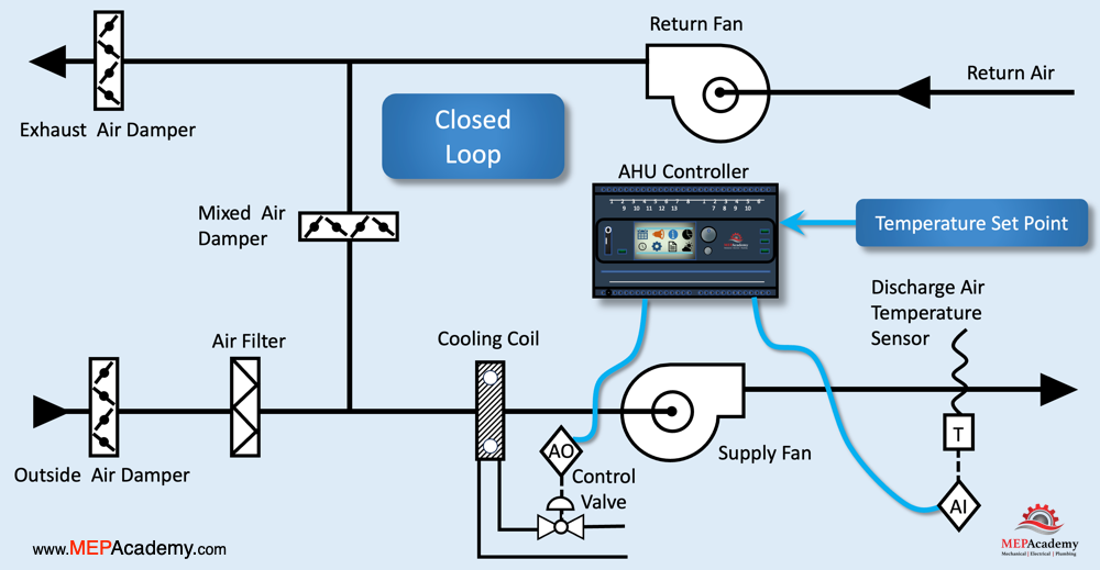
The discharge air temperature is sent to a controller in the form of an analog input. The controller compares the actual discharge air temperature to the desired set point temperature.
The controller sends an output signal to the coil control valve, which is responsible for regulating the flow of heating hot water or chilled water through the coil. The control valve is positioned by the controller based on the comparison between the actual and desired discharge air temperatures.
If the actual discharge air temperature is higher than the setpoint, it indicates that more cooling is needed. The controller signals the control valve to open, allowing more chilled water to flow through the coil.
If the actual discharge air temperature is lower than the setpoint, it suggests that the space is adequately cooled. The controller instructs the chilled water control valve to close or reduce the flow, reducing the cooling effect. The heating hot water response in a similar manner.
This entire process forms a closed-loop system. The controller continuously receives feedback from the discharge air temperature sensor and adjusts the coil control valve to maintain the desired discharge air temperature.
Benefits
Energy Efficiency: By precisely controlling the coil operation, the system optimizes energy consumption.
Comfort: Consistent discharge air temperature ensures a comfortable environment for occupants.
In summary, a closed-loop system using a discharge air temperature sensor and a coil control valve allows for real-time adjustments to maintain a stable and desired supply air temperature from the cooling coil or heating coil in an HVAC system.
Open Loop System for Heating Hot Water Temperature Reset
In an open-loop control system using an outside air temperature sensor and a 3-way heating hot water control valve, the goal is to reset the hot water setpoint of a boiler based on the outside air temperature. Here’s a breakdown of how this system typically operates:
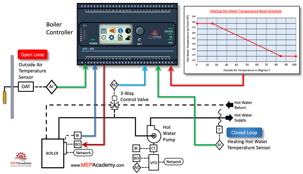
An outside air temperature sensor is located outdoors to measures the ambient temperature. The information gathered by the outside air temperature sensor is crucial for determining the heating requirements based on the actual outdoor temperature conditions.
The outside air temperature from this sensor is sent as an analog input to the boiler’s controller. The controller analyzes the outside air temperature and compares this to the Heating Hot Water Temperature Reset Schedule programmed into the controller before deciding on whether to adjust the set point temperature.
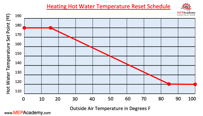
The controller lowers the hot water supply temperatures set point as the outside air temperature increases. When the outside air temperature gets colder, the boiler controller increases the heating hot water supply temperature set point.
Closed Loop using a Temp Sensor
Using a closed loop control sequence, the hot water temperature sensor sends an analog input signal to the boiler’s controller indicating the current temperature of the heating hot water. The boilers controller will compare the reset schedule with the current hot water temperature and send an analog output signal to adjust the 3-way valve to either increase or decrease the flow based on the current water temperature.
The 3-way control valve is responsible for controlling the flow of hot water in the heating system based on the analog output signal from the controller. It has three ports and can direct the flow in different ways based on the control signals it receives.
As the outside air temperature changes, the controller adjusts the set point temperature of the boiler and if required will send a signal to the 3-way hot water control valve to meet the current demand. This adjustment is based on the heating hot water reset schedule.
When the outside temperature is lower, indicating colder weather, the controller will adjust the boiler supply water temperature upwards. This is based on the HHW reset schedule. An analog output to the 3-way valve will more hot water to flow into the system. This will increase the temperature of the heating medium.
Conversely, in milder weather, the controller may adjust the 3-way valve to allow less hot water into the system. Thereby reducing the temperature of the heating medium.
Benefits
Energy Efficiency: By resetting the hot water setpoint based on outside conditions, the system optimizes energy usage by providing only the necessary amount of heat.
Weather Adaptation: The system can automatically respond to changes in external temperature, ensuring efficient heating in various weather conditions.
In summary, an open-loop system using an outside air temperature sensor and a 3-way hot water control valve allows for real-time adjustments of the hot water setpoint of a boiler based on external temperature conditions. This approach helps optimize energy consumption and provides effective heating in response to changing weather patterns.
