


In this article we’ll show you some basic DDC control points used for the control of an air handler. Your situation may be different, but this will give you an idea of the optional points that can be used for various sequences of operation. The examples will build the DDC controls one point at a time and explain its purposes as we build the control diagram.
First we’ll start with a constant volume air handler that has a supply and return fan. Then, we’ll build this AHU to be a variable volume air handler. The advantage of a VAV air handler is that it can optimize the diversity of the zones to save energy by reducing fan speed. There are heating hot water and chilled water coils.
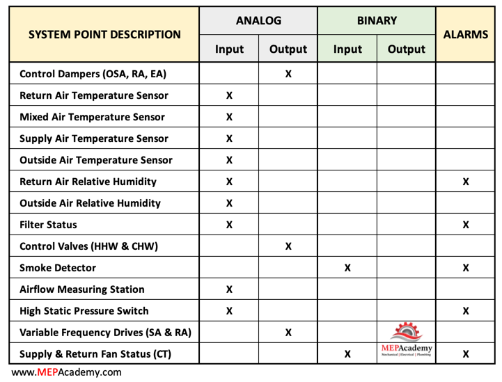
We’ll also build a controls points list as we add the various DDC components for controlling the air handler.
If you prefer to watch the video version of this presentation, then scroll to the bottom.
Control Dampers
Three dampers are added, which include the outside air, return air, and exhaust air dampers. These dampers will have actuators that will allow the DDC controls to adjust the damper positions to meet the system requirements. They will be actuated by 24 volts power. See Control Dampers on Amazon.

Temperature Sensors – DDC Controls
Return Air Temperature Sensor
The return air temperature sensor monitors the temperature of the air returning to the HVAC system from the conditioned space. This information is essential for assessing the thermal conditions within the building. The sensor provides input to the HVAC DDC controls, helping it to regulate the temperature by adjusting the heating or cooling output as needed. It contributes to the overall climate control strategy of the building.
Checkout

Mixed Air Temperature Sensor
The mixed air temperature sensor monitors the temperature of the air after it has been through the return air and outdoor air streams. This information is used to control the mixing of these two air streams to achieve the desired supply air temperature. In HVAC systems, maintaining the right temperature in the supply air is crucial for providing comfortable conditions within the building. The mixed air temperature sensor helps optimize the operation of heating and cooling components to achieve the desired supply air temperature.
By accurately measuring the mixed air temperature, the HVAC system can adjust the mixing ratio of return air and outdoor air to maximize energy efficiency. This is important in commercial buildings where energy costs are a significant consideration.
The mixed air temperature sensor plays a role in preventing issues such as coil freezing or overheating. By monitoring the temperature of the air entering the HVAC system, it helps ensure that the components, like heating or cooling coils, operate within safe temperature ranges.
Supply Air Temperature Sensor
The primary function of the supply air temperature sensor is to continuously monitor the temperature of the air being discharged from the air handler. This sensor provides real-time feedback on the actual temperature of the conditioned air.
The supply air temperature sensor is an integral part of the HVAC control system. The data from the sensor is used as input for the control algorithms that regulate the operation of heating or cooling components to achieve and maintain the desired supply air temperature.
The sensor’s feedback is crucial for the control system to adjust the operation of heating or cooling elements, such as coils or dampers, to achieve the setpoint supply air temperature. This regulation ensures that the conditioned air delivered to the occupied spaces meets the specified comfort requirements.
By accurately measuring the supply air temperature, the HVAC system can optimize its operation for energy efficiency. This is essential for managing energy consumption and operational costs in commercial buildings.
The supply air temperature sensor helps prevent issues such as overheating or underheating of the conditioned air. If the temperature deviates from the setpoint, the control system can take corrective actions to ensure the air supplied to the building is within the desired temperature range.
Outside Air Temperature Sensor
The outside air temperature sensor is crucial for the control of economizer systems in air handlers. Economizers utilize outdoor air for cooling when the outdoor conditions are favorable. The sensor helps determine whether the outdoor air is suitable for free cooling, allowing the system to reduce reliance on mechanical cooling and improve energy efficiency.
The sensor provides input for temperature reset strategies. The supply air temperature setpoint may be adjusted based on the outdoor air temperature to optimize the system’s efficiency. This can help achieve energy savings by adapting to varying external conditions.
In cold climates, the outside air temperature sensor is used to control preheating systems. It ensures that the incoming outdoor air is appropriately conditioned to prevent freezing and improve the efficiency of the HVAC system.
The sensor plays a role in freeze protection strategies. If the outside air temperature drops to levels that could lead to freezing conditions, the system can take preventive measures, such as adjusting the heating elements or modulating the supply air temperature to avoid damage to components.
In systems with heat recovery units, the outside air temperature sensor helps optimize the efficiency of heat recovery. The sensor provides input for controlling the flow of outdoor and exhaust air to maximize energy transfer between the air streams.
The outside air temperature sensor may also be used in conjunction with cooling towers. It provides data to control the operation of cooling towers based on the outdoor conditions, ensuring efficient cooling when needed.
Outdoor air temperature can impact humidity levels. The outside air temperature sensor may contribute to humidity control strategies by influencing the operation of humidification or dehumidification systems based on external conditions.
Space Temperature Sensor
The primary function of the space temperature sensor is to continuously monitor the temperature within the occupied zone. This sensor provides real-time feedback on the actual temperature where building occupants are present.
The space temperature sensor is an integral part of the HVAC control system. The data from the sensor is used as input for the control algorithms that regulate the operation of heating or cooling components to achieve and maintain the desired space temperature.
The sensor’s feedback is crucial for the control system to adjust the operation of heating or cooling elements, such as terminal units or dampers, to achieve the setpoint temperature in the occupied zone. This regulation ensures that the space remains within the specified comfort range.
The space temperature sensor can be integrated with occupancy sensors to adjust the temperature based on occupancy status. During unoccupied periods, the system may enter setback modes to conserve energy, and the space temperature sensor plays a role in this strategy.
Current Transducer
The current transducer is used to confirm that the fan is running. The current transducer detects current flowing through the electrical power cables serving the fan. There will be one for the supply fan and another for the return fan. Checkout

Filter Differential Pressure Sensor
The filters differential pressure sensor monitors the pressure drop across air filters in the HVAC system. As filters accumulate dust and particulate matter, the pressure drop across them increases. An increase in pressure drop indicates that the air filters are becoming clogged with contaminants. The sensor provides real-time feedback on the differential pressure, serving as an indirect measure of filter cleanliness. Checkout Filter Differential Pressure Sensors on Amazon.

By continuously monitoring the differential pressure, the sensor helps determine when the air filters have reached a point where they need replacement or cleaning. This information is crucial for maintaining optimal system performance and indoor air quality.
Regularly changing or cleaning air filters in response to the information from the differential pressure sensor helps maintain the HVAC system’s energy efficiency. Clean filters allow for proper airflow, reducing the system’s energy consumption.
Control Valves – DDC Controls
The primary function of the chilled water control valve is to regulate the flow of chilled water through the system to achieve the desired cooling effect. It controls the amount of chilled water entering the cooling coils. Checkout Motorized Ball Valves on Amazon.

The chilled water control valve helps match the cooling capacity of the HVAC system to the building’s actual cooling load. This ensures that the system operates efficiently and doesn’t waste energy by overcooling spaces.
By modulating the flow of chilled water based on the cooling demand, the control valve contributes to energy efficiency. It helps prevent unnecessary energy consumption by delivering the right amount of cooling precisely when and where it’s needed.
Smoke Detector
The primary function of a smoke detector in an air handler is to detect the presence of smoke in the air circulating through the HVAC system. Early detection is crucial for initiating prompt responses to potential fire situations.
Smoke detectors in air handlers contribute to fire prevention by identifying the presence of smoke particles before an actual fire develops. This early warning allows for timely intervention to address potential fire hazards.
If the smoke detector detects smoke, it is typically integrated into the HVAC system’s control logic. Once activated, it can initiate an automatic shutdown of the air handler to prevent the spread of smoke throughout the building.
Smoke detectors are equipped with alarm signaling capabilities. When smoke is detected, the smoke detector can trigger audible and visual alarms, alerting building occupants and personnel to the potential fire hazard.
Airflow Measuring Station
The airflow measuring station ensures that the proper amount of outside air enters the air handler by adjusting the outside air damper.
High Static Pressure Switch
High duct-static pressure poses challenges in the event of a building fire when fire dampers are activated. During a fire, the closure of fire dampers results in downstream duct sensors detecting a pressure drop. Subsequently, these duct pressure sensors transmit signals to increase the air handler’s speed even further to restore normal operation.
However, due to the closed fire dampers, the ramping up of the air handler causes an increase in duct pressure upstream of the fire dampers. This increase reaches a threshold where a high static pressure switch intervenes, cutting power to the Variable Frequency Drive (VFD) and transmitting a signal to the Direct Digital Control (DDC). Notably, switches in this specific application adhere to specifications, requiring manual reset and dual outputs: one for disengaging power to the VFD and another for signaling the DDC controls.
Variable Frequency Drives (VFD’s)
One of the primary functions of a VFD on the supply fan is to enhance energy efficiency. The VFD allows the speed of the fan motor to be adjusted based on the actual demand for airflow. This prevents the fan from running at full speed constantly, which can result in energy savings, especially during periods of partial load. Checkout Variable Frequency Drives on Amazon.

The VFD provides precise control over the speed of the supply fan, allowing for fine adjustments to the airflow. This is particularly beneficial in systems with variable air volume (VAV) requirements or in response to changing building loads. The ability to modulate the fan speed ensures that the system meets the specific ventilation and comfort needs of the space.
Soft Starts and Stops
VFDs enable soft starts and stops for the supply fan motor. This reduces mechanical stress on the motor and the associated components, extending the lifespan of the equipment. The gradual acceleration and deceleration also contribute to smoother operation.
In response to changes in the building’s heating or cooling requirements, the VFD adjusts the fan speed dynamically. This allows the HVAC system to respond quickly and efficiently to fluctuations in temperature or occupancy, maintaining optimal conditions within the building.
VFDs on supply fans can be integrated with building automation systems to control the air pressure within the HVAC system. This is particularly important in systems with variable air volume, where maintaining the right pressure helps optimize the performance of terminal units and other components.
The ability to adjust the speed of the supply fan based on demand contributes to significant energy cost savings over time. By avoiding unnecessary energy consumption during periods of low demand, a VFD helps keep operational costs in check.
Many energy codes and standards encourage or require the use of VFDs in HVAC systems to meet energy efficiency goals. By incorporating a VFD on the supply fan, a system can align with these codes and standards, ensuring compliance.
DDC Control Points for VFD
The specific Direct Digital Control (DDC) control points for a Variable Frequency Drive (VFD) on a supply fan in an HVAC system can vary based on the system design, the control strategy employed, and the building’s requirements. However, here are some common DDC control points associated with a VFD on a supply fan:
Setpoint Control: Fan Speed Setpoint: The desired speed or frequency at which the VFD should operate the supply fan. This setpoint can be adjusted based on the building’s heating, ventilation, and air conditioning needs.
Feedback Signals: Actual Fan Speed: The real-time speed of the supply fan as measured by sensors. This feedback signal allows the DDC controls to compare the actual speed with the setpoint for precise control.
Motor Current: Monitoring the current drawn by the fan motor provides information on the motor’s load. Abnormal current levels may indicate issues such as mechanical problems or belt tension.
Safety and Fault Monitoring: Motor Overload Protection: DDC controls can be programmed to monitor motor current and provide protection against overloads. If the current exceeds a specified threshold, the system can take corrective actions or initiate an alarm.
VFD Faults
Monitoring for faults in the VFD, such as overvoltage or overcurrent, and providing alerts or triggering safety protocols in case of a fault.
Soft Start and Stop Parameters: Acceleration/Deceleration Time: Controlling the rate at which the fan motor accelerates or decelerates to prevent sudden starts or stops, reducing stress on the equipment.
Pressure Control: Duct Pressure Setpoint: In systems with variable air volume (VAV), the DDC controls may control the VFD based on the desired pressure setpoint in the ductwork. This ensures proper air distribution and terminal unit performance.
Occupancy and Schedule Control: Occupancy Status: Integration with occupancy sensors to adjust the fan speed based on the building’s occupancy status, optimizing energy usage.
Scheduling: Modifying the DDC Controls setpoint or operation schedule of the VFD based on the time of day or specific building requirements.
Energy Efficiency Measures: Demand-Based Control: Adjusting the fan speed based on the actual demand for conditioned air, optimizing energy usage.
Energy Monitoring: Tracking energy consumption and providing data for analysis to identify opportunities for further efficiency improvements.
Return Air Relative Humidity Sensor
The primary function of the return air relative humidity sensor is to continuously monitor the relative humidity level of the air that is being drawn back into the HVAC system from the occupied spaces.
The sensor is an integral part of the HVAC DDC controls system. The data from the return air relative humidity sensor is used as input for control algorithms that regulate the operation of humidification or dehumidification components to achieve and maintain the desired indoor relative humidity level.
The feedback from the sensor is essential for the control system to adjust the operation of humidification or dehumidification elements, such as steam humidifiers or cooling coils, to achieve the setpoint relative humidity. This control is crucial for maintaining a comfortable and healthy indoor environment.
If the return air relative humidity sensor detects that the indoor air is becoming too humid, the control system can take corrective actions to prevent issues such as condensation, mold growth, or discomfort for occupants.
Conversely, if the indoor air is too dry, the return air relative humidity sensor helps the control system adjust humidification measures to prevent issues like dry skin, respiratory discomfort, or damage to sensitive equipment.
Maintaining an appropriate relative humidity level contributes significantly to occupant comfort. The return air relative humidity sensor ensures that the HVAC system responds effectively to changes in humidity, providing a comfortable indoor environment.
The return air relative humidity sensor often works in conjunction with other sensors, such as temperature sensors and occupancy sensors, to provide a comprehensive understanding of the indoor environment. Integrated control strategies can then be employed to balance temperature and humidity for optimal comfort and energy efficiency.
Outside Air Relative Humidity Sensor
The primary function of the outside air relative humidity sensor using DDC controls is to continuously monitor the relative humidity level of the outdoor air before it enters the HVAC system.
The sensor is an integral part of the HVAC control system. The data from the outside air relative humidity sensor is used as input for control algorithms that regulate the operation of humidification or dehumidification components to achieve and maintain the desired indoor relative humidity level.
The sensor helps in controlling the humidity levels of the outdoor air that is brought into the building for ventilation purposes. This is particularly important for maintaining a comfortable indoor environment and preventing issues associated with excessively high or low humidity.
High Relative Humidity
If the outside air relative humidity is too high, the control system can take preventive actions to avoid introducing excessively humid air into the building. This helps in preventing indoor humidity issues and contributes to occupant comfort and health.
Conversely, if the outside air is too dry, the sensor helps the control system adjust humidification measures to prevent introducing overly dry air into the building. This is important for preventing issues related to dry skin, respiratory discomfort, and static electricity.
By accurately monitoring and controlling the humidity levels of the outdoor air, the HVAC system can optimize its operation for energy efficiency. This is crucial for managing energy consumption and operational costs in commercial buildings.
The outside air relative humidity sensor may work in conjunction with other sensors, such as temperature sensors and airflow sensors. Integrated control strategies can be employed to balance temperature and humidity for optimal comfort and energy efficiency.
In air handling units that use outdoor air for cooling or ventilation, the outside air relative humidity sensor plays a role in adjusting the humidity level of the mixed air. This ensures that the air supplied to the building is within the desired relative humidity range.
Understanding the function of the outside air relative humidity sensor is crucial for designing and maintaining HVAC systems that prioritize indoor air quality and occupant comfort in commercial buildings. It helps ensure that the system responds effectively to variations in outdoor humidity, contributing to overall comfort and health within the building.
