We’ll discuss the basics of How Variable Frequency Drives (VFD’s)Work in HVAC Systems, also referred to as Variable Speed Drives (VSD’s), which are used in the Mechanical Construction Industry for the control of motors that run fans, pumps, and compressors. We’ll discuss where VFD’s are used in the MEP Construction Industry, Identify the key components of a VFD and how to select a Variable Frequency Drive.
If you prefer to watch a Video of this presentation than scroll to the end this article for our YouTube Video.
Be sure to shutoff any electrical power when working with a VFD.
Motor control equipment and electronic controllers are connected to hazardous line voltages. Extreme care should be taken to protect against shock and possibility of a fatality.
Where are VFD’s used in the Mechanical Construction Industry?
Pump Control with VFD’s
The use of VFD’s to control the motor speed of pumps is widely used in commercial construction projects. There are various control strategies, and as the image shows this one uses a “Differential Pressure Transmitter” to control the speed of the pump, which controls the flow (GPM) based on demand.
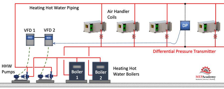
As the HHW control valves open due to an increase in demand for heating hot water, the pressure drops in the piping which is sensed by the Differential Pressure Transmitter. The transmitter sends a signal to the Variable Frequency Drive to speed up (increase flow – GPM), causing the pump to push more water through the pipes. The opposite happens when the heating hot water valves start to close because the space is warm enough. The valves start closing causing an increase in pressure in the piping which is sensed by the differential pressure transmitter. The transmitter sends a signal to the Variable Frequency Drive to slow down the pump motor, reduces the flow (GPM).
Checkout these Variable Frequency Drives hereFan Control with VFD’s
The theory is the same for controlling the speed of the fan motor. There is some form of monitoring of the supply air duct which will cause an adjustment to the speed of the fan. In the scenario below we show that a “Static Pressure Sensor” is located two-thirds of the way down the main supply air duct. The sensor will pick up changes in pressure within the duct.
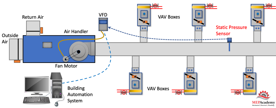
As the Variable Air Volume (VAV) boxes begin to open their dampers because of an increase in cooling demand, the pressure in the supply duct drops. When the pressure in the supply air duct decreases, the Static Pressure Sensor sends a signal to the Variable Frequency Drive to increase the speed (RPM) of the fan motor, causing an increase in CFM. The opposite happens when the VAV box dampers begin to close because the spaces are cold enough. As the dampers begin to close the pressure in the supply air duct increases, causing the Static Pressure Sensor to send a signal to the VFD to slow down the motor of the fan, reducing the amount of CFM. See our video on Variable Air Volume Systems.
Compressor Control with VFD
Chillers come with various options for variable speed control. Check with your Chiller manufacture for chillers with Variable Speed Drives. As the load in the building decreases, the chiller can change the speed of the motor that turns the compressor, thereby reducing the energy consumed.
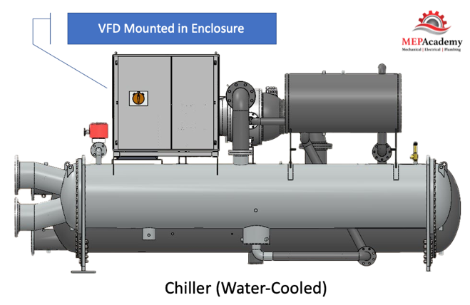
By reducing the speed of the compressor the output tonnage of the chiller is matched to the demand. Variable Speed Drives (VSD) come mounted in an enclosure mounted on the chiller.
Checkout these Variable Frequency Drives hereOld Methods of Volume Control
To control the volume of air (CFM) or water (GPM) using constant speed motors required putting an artificial load on the system. This method of flow control waste energy. Fans used dampers to impose flow restrictions, while pumps used valves (throttling) to dial back the GPM flow of water or just bypassed the water. These methods generate restrictions to flow that waste energy. Controlling the varying flow requirements with a VFD saves on this lost energy.
In the HVAC industry the use of Variable Air Volume System is very common. To control the various cooling and heating load fluctuations during the year the Air Handler fan will vary the volume (CFM) delivered to the space. The same applies to the Chilled Water, Heating Hot Water or Condenser Water flow (GPM) through the pipes as the load on the building changes through-out the year. In older HVAC piping systems with constant flow pumps the use of 3-way valves was common. Instead of reducing the flow (GPM), the water would bypass the coil through the 3-way valve. Obviously this is a waste of energy as the pump is just circulating water that is not needed.
What Is the Purpose of a Variable Frequency Drive VFD?
The main purpose of a Variable Frequency Drive (VFD) is to vary the speed of a motor by varying its frequency and voltage to provide for energy savings. By increasing the frequency you can increase the speed of the motor, and by decreasing the frequency you can decrease the speed of the motor, it’s basically that simple.
Many of the existing motors that control mechanical equipment were originally designed to run at constant speed, which isn’t energy efficient. These older motors were either in the on or off position and used some form of artificial resistance to control flow.
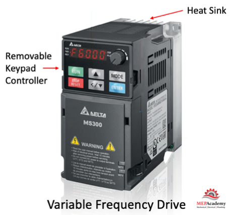
How to Choose a Variable Frequency Drive VFD
Selecting a Variable Frequency Drive can be very simple when you know the Voltage, Current and the Power Rating.
When bidding a plans and specifications project the mechanical engineer will have sized and documented the required VFD on the equipment schedule. If you’re doing a Design/Build project or Retrofit where you’ll be responsible for the selection of the variable frequency drive, then knowing the basic’s for selecting a drive is crucial. If you’re not comfortable with selecting a Variable Frequency Drive there are many VFD suppliers that will help you choose the correct drive.
Checkout these Variable Frequency Drives hereHere are a few things to consider when selecting a Variable Frequency Drive (VFD) for an existing motor on your project. Values are from example motor nameplate below.
- Full Load Amps (FLA) 40-37/18.3
- Horsepower (Hp) 15
- Voltage (V) 208-230/480
- Speed (RPM) 1775
- Motor Type – (Inverter-duty Rated)
- Method of Control I/O (Static Pressure Sensor, Differential Pressure Transmitter)
- NEMA Enclosure type. (Inside, Outside, Exposure to elements)
The first place to start on an existing motor is the motor name plate. This is where most of what you need can be found. Hopefully the building engineer hasn’t removed them or painted over them.
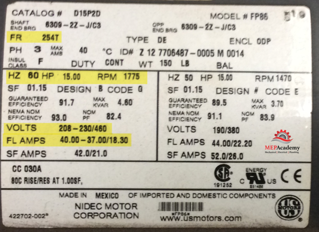
Motor Nameplate
The motor name plate may indicate more than one voltage and its corresponding amperage. The above name plate indicates 230 and 460 volts, with a corresponding 37 and 18.3 amps. The higher the voltage the lower the amps.
Full Load Amps (FLA)
The full load amps (FLA) is one of the important aspects of the Variable Frequency Drive VFD selection process. For existing motors this number will be on the motors nameplate, and shown as 40-37/18.3 on example nameplate. Why three values? Each FLA corresponds to what voltage is used, either 203 Volts (40 FLA), 230 Volts (37 FLA) or 460 Volts (18.3 FLA)
Frame Number
The NEMA frame number can be two or three characters and represents the distance from the center of the motor shaft to the center bottom of the mounting plate. Such as in our example of a frame number of 254T. This equals 254/16 = 15.875”
Method of Control
If the VFD is for controlling a fan in a VAV Air Handler, then the controller may be a “Static Pressure Controller”, see our Video on Variable Air Volume Systems that explains this further. If for a pump, may be your using a “Differential Pressure Controller”. Whatever system variable is being measured the Input and Output (I/O) signals need to be setup in the VFD.
NEMA Enclosure Type
The Variable Frequency Drives are usually located in Mechanical Rooms or Outside near the equipment. Depending on the type of environment that surrounds the VFD, there are various solutions for the enclosure type as indicated by the NEMA number. The most common in the Mechanical industry is NEMA 1, 3R and 12.
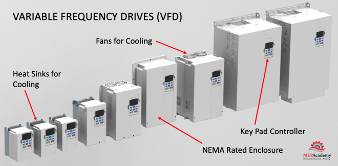
NEMA 1 Rated enclosures are made for Indoors with no water protection. NEMA 3R is rated for Indoor or Outdoor use, and where rain, snow or ice may form. NEMA 12 is rated for Indoors and with dust, lint and other dirt circulating in the air, along with minor water splashes. There is an enclosure for any environment.
Since VFD’s produce heat during operation, this must be part of the consideration when selecting a ventilated enclosure versus a cooled enclosure. Avoid locating a VFD on a heated wall or in direct sunlight.
Checkout these Variable Frequency Drives hereVariable Frequency Drive – VFD Components
Bypass
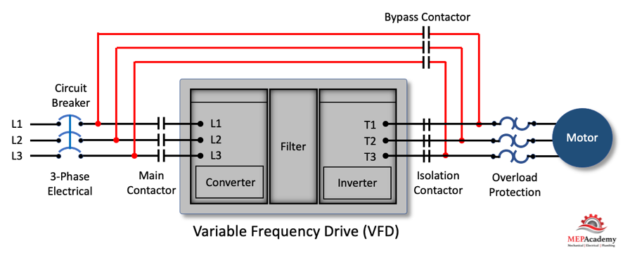
The bypass provides a means for circuiting around the drive and providing power to the motor. You have to be sure that in bypass mode the motor still has some form of overload protection. Purchasing a Bypass adds substantial cost to a VFD. If its not needed or you can afford some down time with the equipment, then avoid purchasing a bypass or if you have several VFD’s of the same size, just purchase an extra drive for emergency replacements.
VFD Keypads and Control Panels and Remote Monitoring
If the location of the VFD is inaccessible or inconvenient for the maintenance staff, you could mount the VFD’s Keypad remotely. You may need additional cabling, so check with the VFD manufacture.
Navigating is easy using the control panel to set various parameter values. Various VFD manufacturers drives have the capability of copying settings from one drive to others. The control panels provide a touchscreen graphical display in various sizes from 3.5” up to 15”
Look for optional remote monitoring that allows you to view and control the drive from any location with web access.
The available menu items will vary by VFD manufacturer and how they are displayed, but there are some basic common features. There will be a way to adjust the speed, bypass the VFD if provided with a Bypass, alarm and fault indicators, on/off/auto, indication that either the I/O Terminal/Keypad or Communication Bus is chosen for control of start/stop – signals.
Input Line Reactors and Harmonics
To protect the VFD from the utility companies possible power fluctuations an input line reactor is installed. The Input line reactor also helps mitigate the harmonics associated with the use of variable frequency drives.
Physical Size
Small drives can be anywhere from 12” in height to over 60”. The weight of a small drive can be 10 pounds to over 500 pounds for larger drives.
VFD Cooling Requirements
There are two methods to keep Variable Frequency drives cool; air-cooled and liquid-cooled. Liquid-cooled is used on larger VFD’s, so most likely you’ll be dealing with air-cooled drives. Cooling is required to remove heat from the semi-conductors and ancillary devices used in the VFD.
The VFD’s require space around them for the proper flow of air through the cabinet to allow for cooling the drive. Be sure to check the mounting instructions to avoid overheating a drive and causing premature failure. Small VFD’s require anywhere from 40 CFM to over 1,000 CFM for larger drives. Check the drive manufacturers requirement for space around the drive and their method of cooling the unit. The area around the air-cooled VFD should be kept clean, dry and free of dust.
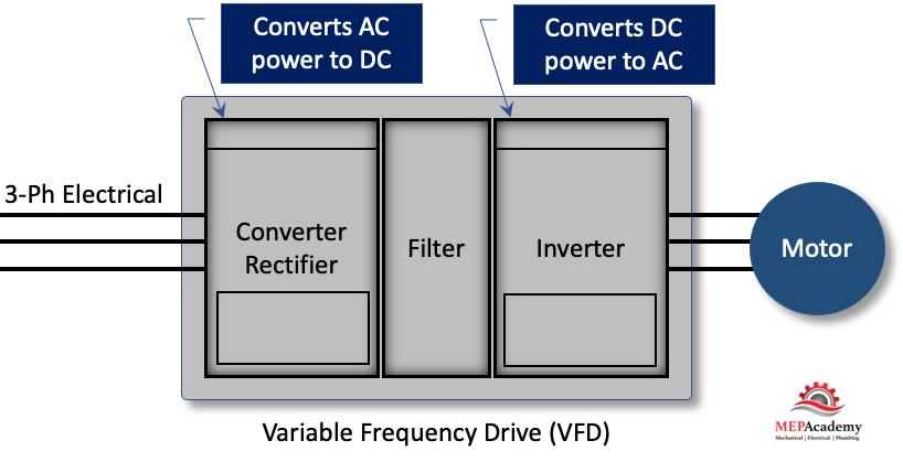
Three Main Components of a VFD
The following are the three main components that convert AC Voltage to DC Voltage and then back again using a simulated AC Voltage.
Converter (Rectifier)
The converter takes the incoming 3 phase Alternating Current (AC) power and converts into Direct Current (DC) power.
Filter
The filter smooths out and rectifies the DC voltage.
Inverter
The inverter rapidly switches the Direct Current (DC) on and off to create a pulsating voltage that mimics AC voltage. By controlling the rate of switching the frequency can simulate AC power applied to the motor to control its speed. So, basically switch from DC back to AC.
Controls Integration
The VFD’s have the ability to communicate over Ethernet with ModBus TCP or EtherNet/IP, also LonWorks, ModBus RS-485 interface and various other protocols. This gives your building automation or controls system the ability to monitor the status of various functions such as speed (RPM), Amperage (Amps), and any system faults or errors.
There are options to add additional digital or analog input and output modules to expand on the ones provided with the base unit.
VFD Building Codes and Standards
Some standards such as California’s Title-24 building code require VFD’s on aal HVAC Fans and Pumps with a Horsepower (HP) greater than 10 Hp. Be sure to check with your local code jurisdiction for these requirements. Also, motors that are manufactured over 1 Hp are required to be compatible for variable frequency drives applications per the National Electrical Manufacturers Association (NEMA).
There are various other rules and regulations related to motors that are beyond this scope, such as the Department of Energy (DOE) Small Motor Rule, to 10 CFR Part 31 Energy Conservation Program (1/4 to 3 Hp), and guidelines established by the Energy Independence & Securities Act (EISA)(Minimum efficiencies for motors over 1 Hp).
Benefits of a VFD
Saves Energy
The main reason is to save energy by adjusting the speed of the motor to better match the varying load of the equipment. Motors consume a large portion of the energy used in buildings, so any improvement makes a big difference. Instead of running motors at full speed all the time, the use of VFD’s allows for saving energy when motor speeds can be reduced. This is also accomplished because a VFD won’t pull a high amperage draw like traditional motors rated for their Lock Rotor Amps (LRA), thereby saving the facility on electrical demand charges.
Ease of Installation and Operation
Variable Frequency Drives are easy to install on a wall or mounted in a cabinet. The drives are very simple to operate and to adjust the speed or other settings.
VFD Rebates & Incentives
Check with your local utility company for rebates and with taxing authorities for tax incentives. The investment for the installation of VFD’s usually pays back in a short period of time. After the payback period the investment in VFD’s begins to provide an annual cost savings that increases net income for the business.
VFD Maintenance and Equipment Life
By avoiding the constant speed motors inherent need to cycle on and off to provide control of system requirements, you can extend the life of your equipment. The VFD provides for soft starts that provides better protection of the motor, belts, gears and wearing of the bearings.
With a reduction in speed of a pump, there is a reduction in the forces within the pump casing which is carried by the pump bearings, so reducing speed increases bearing life. In addition, vibration and noise are reduced and seal life is increased, provided that the duty point remains within the allowable operating range.
With air-cooled VFD’s they need to be periodically inspected and their air-filters cleaned.
Motor Speed (RPM) – Affinity Laws
By adjusting the frequency (hertz) of the motor we can either slow down or speed up the fan, pump, or compressor. This is in direct relationship to the affinity laws where adjusting the speed (RPM) affects Flow (CFM or GPM), Pressure and Power. Checkout these video’s on Infinity Laws or this one on Variable Air Volume Systems using VFD’s.
Affinity Law #1 (Flow)
When adjustments are made to the speed of the motor, the flow is directionally proportional. So, if you cut the speed (RPM) in half, then you’ll cut the air or water flow (CFM, GPM) in half. A 50% reduction in speed is equivalent to a 50% reduction in flow. This applies to closed loop water systems.
CFM1 = CFM2 x (RPM1/RPM2) or GPM1 = GPM2 x (RPM1/RPM2)
Affinity Law #2 (Pressure)
The relationship of speed to pressure has a greater effect upon pressure when reducing the speed. For every adjustment in speed, there is a corresponding reduction in pressure to a quarter of what it was. So if you adjust the speed by 50% you get a 25% of the pressure
Pressure1 = Pressure2 x (RPM1/RPM2)2
Affinity Law #3 (Power)
This is where the greatest effect occurs when reducing the speed (RPM) using a VFD. When reducing the speed by half (50%) you’ll have power at one-eight. By reducing the speed of the motor attached to a fan, pump, or compressor you’ll save a greater proportion of power. The power is proportional to the shaft speed, cubed as shown in the formula below.
Power1 = Power2 x (RPM1/RPM2)3
Motor Starting Methods
There are various methods used to start motors with advantages and disadvantages for each. Using a Variable Frequency Drive provides for smooth starting and stopping.
The typical motor starter causes an inrush of current (amps) that is around 6 times higher than what is required when running the motor at full speed. The use of various soft start options still lack the ability for speed control of the motor. This is where the use of a Variable Frequency Drive provides for a soft start and the ability to control the speed of the motor for energy efficiency.
Other Names for Variable Frequency drives (VFD’s)
The following are various names used to describe the same thing as a VFD
- Variable Speed Drives (VSD)
- Adjustable Speed Drives (ASD)
- Adjustable Frequency Drives (AFD)
- Frequency Converters
- Inverters
Summary
The use of a VFD will save energy and money, provide better control and reduce maintenance cost. The payback should be short depending on run time hours, utility cost and variable flow profile.


