

")
In modern data centers, cooling is one of the largest operational challenges—and one of the biggest drivers of energy cost. While advanced cooling systems like chilled water plants and CRAH units play a major role, one of the most effective strategies is much simpler: controlling how air moves through the data hall.
Hot aisle and cold aisle containment are foundational concepts in data center design. When implemented correctly, they improve efficiency, reduce energy consumption, extend equipment life, and enhance overall reliability.
In this guide, we’ll break down how hot aisle and cold aisle configurations work, what containment systems do, and why airflow management is critical in today’s high-density data centers.
Watch the Full Breakdown
Why Airflow Management Matters in Data Centers
Every server generates heat as it processes data. Multiply that across hundreds or thousands of racks, and the result is a massive and continuous heat load.
Servers are designed to operate within specific temperature ranges. To maintain those conditions, cold air is supplied to the front of the equipment, while hot air is exhausted from the back.
The challenge arises when hot and cold air mix.
When this happens:
- Cooling systems must work harder to maintain temperature
- Energy consumption increases
- Hot spots can develop, putting equipment at risk
- Overall system efficiency drops
The goal of airflow management is simple: keep hot air and cold air separated.
Understanding Cold Aisle Configuration
The cold aisle layout is the most common starting point in data center design.
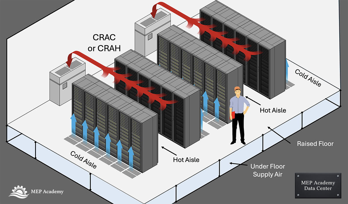
Server racks are arranged in rows so that the fronts of the racks face each other, forming a corridor known as the cold aisle.
Cold air is delivered into this aisle through:
- Raised floor perforated tiles
- Overhead supply duct systems
Servers pull this cold air into their front intakes. After passing through the equipment, the air absorbs heat and exits through the back of the racks into the adjacent hot aisle.
Advantages of Cold Aisle Layout
- Organized airflow direction
- Improved cooling compared to random rack layouts
- Compatible with both raised floor and overhead systems
Limitations
- Hot and cold air still mix above and around racks
- Cooling efficiency is limited without further control
- Increased energy usage compared to contained systems
Understanding Hot Aisle Configuration
In a hot aisle configuration, racks are arranged so that the backs of the racks face each other, forming a dedicated hot air corridor.
Hot air is concentrated in this aisle and directed back toward the cooling system.
Benefits of Hot Aisle Layout
- Better capture of hot exhaust air
- Improved return airflow to cooling units
- Reduced mixing compared to unorganized layouts
Remaining Challenge
Even with this configuration, hot air can still escape and mix with cold air unless containment is used.
What is Aisle Containment?
Containment systems take airflow control to the next level by physically separating hot and cold air streams.
This is done using:
- Ceiling panels
- End-of-row doors
- Partition walls or barriers
The purpose is to prevent air mixing entirely, forcing air to follow a controlled path.
There are two primary containment strategies:
- Cold Aisle Containment
- Hot Aisle Containment
Cold Aisle Containment Explained
In cold aisle containment, the cold aisle is enclosed.
This traps the cold air directly in front of the racks, ensuring that servers always receive consistent inlet temperatures.
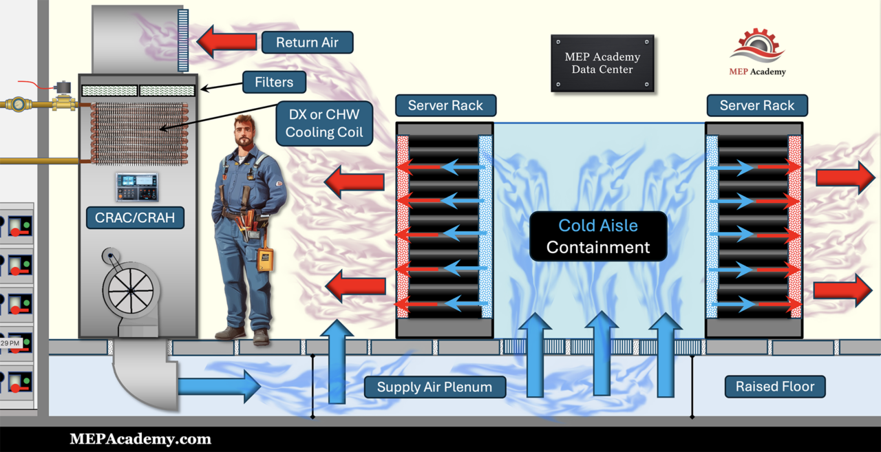
Advantages
- Stable and predictable cooling at the equipment level
- Easier to retrofit into existing facilities
- Lower initial cost compared to hot aisle containment
Disadvantages
- The overall room becomes warmer
- Less efficient at high power densities
- Cooling systems may still work harder than necessary
Hot Aisle Containment Explained
In hot aisle containment, the hot aisle is enclosed instead.
This isolates hot exhaust air and directs it back to the cooling system.
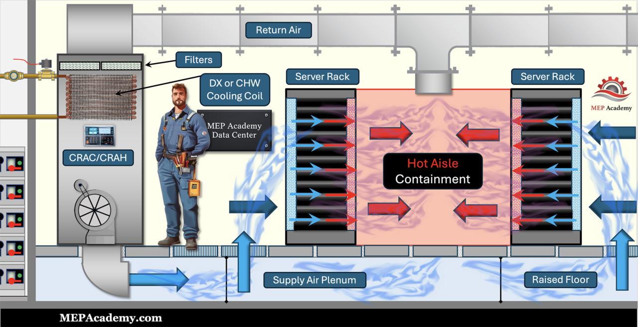
Advantages
- Higher overall energy efficiency
- Better performance in high-density environments
- Improved control of return air temperatures
- Reduced cooling system workload
Disadvantages
- More complex design and installation
- Requires coordination with fire suppression systems
- Higher upfront cost
Hot Aisle vs Cold Aisle: Key Differences
The main distinction comes down to where airflow is controlled.
- Cold Aisle Containment focuses on protecting equipment by ensuring consistent inlet air
- Hot Aisle Containment focuses on improving system efficiency by controlling return air
In modern data centers—especially those with high-density loads—hot aisle containment is generally preferred due to its superior efficiency and performance.
Impact on Energy, Cost, and Performance
Airflow management is not just a design detail—it has measurable impacts across the entire facility.
Energy Consumption
Improved airflow reduces the workload on cooling systems, lowering overall energy use.
Operating Costs
Less energy consumption directly translates into lower utility costs, especially at scale.
Equipment Lifespan
Consistent temperatures reduce thermal stress on servers, extending their usable life.
Reliability
Eliminating hot spots reduces the risk of equipment failure and downtime.
Even small improvements in airflow management can result in significant long-term savings in large data centers.
Why Containment is Critical in Modern Data Centers
As computing demands increase—especially with AI and high-density workloads—heat loads continue to rise.
Traditional cooling strategies alone are no longer enough.
Containment allows data centers to:
- Handle higher rack densities
- Maintain stable operating conditions
- Optimize cooling system performance
- Scale efficiently without excessive energy costs
Without proper airflow control, even the most advanced cooling systems cannot perform effectively.
How This Connects to Cooling Systems
Containment works hand-in-hand with mechanical cooling systems such as:
- CRAC units
- CRAH units
- Chilled water systems
- Air-cooled systems
By controlling where air goes, containment ensures that cooling systems operate at peak efficiency.
Conclusion
Hot aisle and cold aisle containment are fundamental strategies in modern data center design.
They transform uncontrolled airflow into a structured, engineered system that improves efficiency, reliability, and performance.
Whether you are designing a new facility or optimizing an existing one, proper airflow management is one of the most impactful upgrades you can make.
Continue the Series
To understand how these airflow strategies connect to larger cooling systems, continue to the next article:
👉 [Next: Data Center Chilled Water Systems Explained]
Data Center Engineering Series
This article is the hub of our Data Center Educational Series, where we break down each major system in detail.
Currently Published
- How Data Centers Actually Work
An overview of how modern data centers operate, explaining the critical electrical, mechanical, and IT infrastructure required to keep servers running 24/7. - Data Center Power Flow: From Utility Grid to Server Rack
Learn how electrical power travels from the utility grid through switchgear, UPS systems, generators, and distribution equipment before reaching server racks. - Data Center Cooling Methods Explained
Learn how CRAC units, chilled water systems, and airflow management remove heat from server environments. - Data Center Redundancy Explained (N, N+1, and 2N Systems)
Understand how redundancy strategies like N, N+1, and 2N designs protect data centers from outages and ensure continuous operation. - How Data Center Electrical Systems Work
Understand how data center electrical systems deliver continuous power using switchgear, UPS systems, generators, and redundancy design. - Data Center Refrigerant Economizer
Discover how refrigerant economizer systems improve cooling efficiency by using outdoor conditions to reduce compressor operation and lower energy consumption. - Data Center HVAC Systems
- How Data Center UPS Systems Work
Understand how UPS systems provide instant backup power and protect data centers from outages and power disruptions. - Hot Aisle vs Cold Aisle Containment
Hot aisle vs cold aisle containment explained. Learn how airflow control improves data center cooling efficiency and reduces energy costs. - Data Center Chilled Water Systems Explained
Learn how chilled water systems cool data centers, including chillers, CRAH units, pumps, and how the entire system removes heat efficiently. - CRAC vs CRAH Units Explained
Learn the difference between Computer Room Air Conditioners and Computer Room Air Handlers, including how DX refrigerant cooling compares with chilled water cooling in data center environments. - Air-Cooled vs Water-Cooled Data Centers
Learn the difference between Computer Room Air Conditioners and Computer Room Air Handlers, including how DX refrigerant cooling compares with chilled water cooling in data center environments. - Immersion Cooling Explained
Discover how immersion cooling is transforming AI data centers by submerging servers in a non-conductive dielectric fluid for highly efficient heat removal. Learn how single-phase and two-phase immersion cooling work, why AI is driving their adoption, and how these systems compare to traditional air cooling.
Learn More
If you want to learn how these systems are designed and applied in real-world MEP projects, explore our training programs:


")

