How an Air Side Economizer works. There are energy codes that mandate the use of an air-side economizer for HVAC equipment over a certain size. An economizer reduces energy consumption by using the outdoor air for cooling in mild or cold weather instead of mechanical cooling. We’ll cover how an air-side economizer works and show you three different relief air options.
If you prefer to watch the Video fo this presentation, then scroll to the bottom or click on this link How an Air Side Economizer Works.
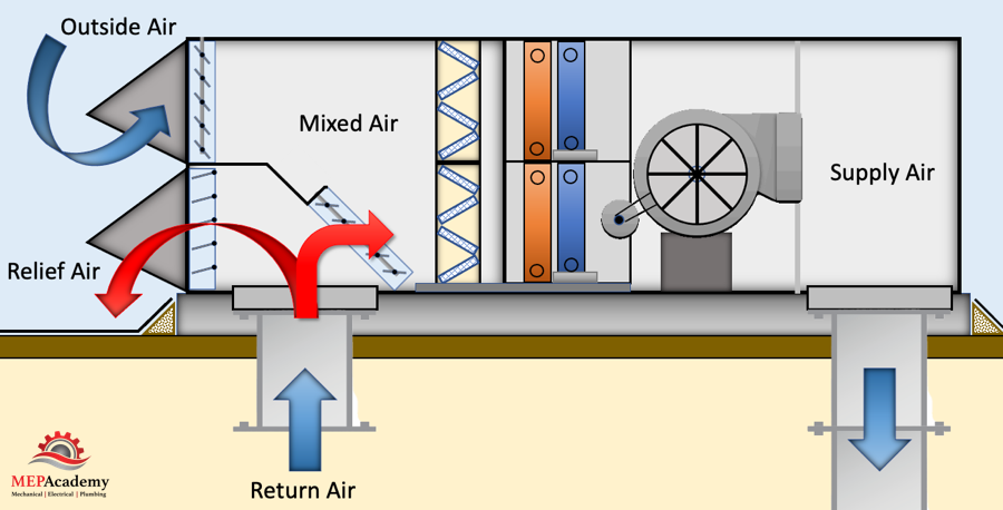
Air-side economizers are used with Packaged Units, Split Systems and Air handlers of all sizes. When the outside air temperature is below the return air temperature, then outside air can be more energy efficient to use for cooling then mechanical cooling.
Here is one control layout of many for controlling an economizer. We have an economizer controller which can be integrated into the economizer section or as a separate controller. Next there will be a thermostat in the space, and a Supply Air Temperature sensor in the supply air discharge duct.
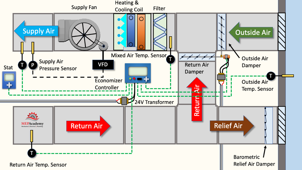
There is a Return Air Temperature sensor in the Return Air Duct. The Economizer Controller will need a transformer to provide 24 volt power. The system will need an outside air temperature sensor and Mixed Air Temperature sensor, and communication with the damper actuator, and the power to modulate the damper.
Economizer Relief/Exhaust Air
One of the important design considerations for an outside air system is how to control building pressure when excess outside air is brought into the space. There are three common approaches for the design of the relief air system. Some engineers may refer to this as exhaust air. The Relief or exhaust air needs to be considered to avoid over-pressurizing the space.
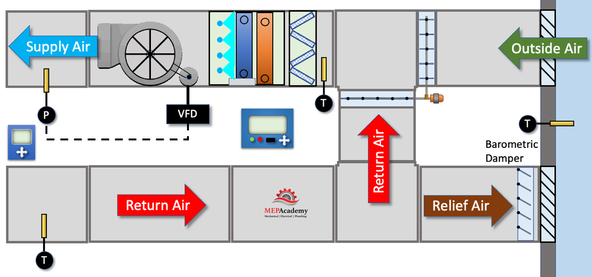
Barometric Damper (Backdraft Damper)
One method is to use relief dampers that are set to open when the building pressure reaches a certain level, such as 0.05” or 12 Pascals. This pressure will be set just below the maximum allowable for the pressure in the building space. This can be a barometric damper with an adjustable weight for varying the pressure relief setting.
As the economizer starts to open the outside air damper, it will modulate the return air damper in the opposite direction, causing the pressure in the building to increase. When the pressure reaches the preset pressure on the barometric relief damper it will begin to open, allowing air to escape the building. When the outside air damper is fully open in 100% economizer mode, the return air damper will be fully closed, causing the pressure in the building to open the barometric damper, allowing excess air to escape the building.
There are many sequences of operation for controlling an economizer. Each situation is unique to the geographical area and desired indoor conditions. We’ll explain the basic premise of the economizer cycle using the supply air temperature setpoint as the controlling factor.
If we set the supply air temperature to 55 degrees Fahrenheit (13 degrees Celsius), then the economizer controller will use this to determine the position of the dampers, along with all the other input points like an “Outside Temperature Sensor”, “Return Air Temperature Sensor”, Supply Air Temperature Sensor”, “Mixed Air Temperature Sensor” and the room thermostat or main controller. It will send an output signal to the damper actuator for the correct mixture of outside air and return air to meet the supply air setpoint.
If the outdoor temperature is below the return air temperature then the outdoor air can be used in situations where a differential dry bulb type of economizer would be used. If in more humid areas, then the outdoor temperature would need to be much lower than the return air temperature to compensate for the increase in humidity.
The purpose of course is to avoid using the compressor or chiller for cooling in order to save energy. If the outside air damper is 30% open, then the return air will be 70% open, so that we have 100% of the air needed by the supply fan. If the outside air damper opens to 80%, then the return air damper will close down to 20% open. If the outside air is not within the useful range of the economizer, than the outside air damper will be set to its minimum setpoint to meet ASHARE 62.1 requirements for ventilation air.
The use of a barometric relief damper is the least expensive option of the three presented here, as there is no electrical connection, sophisticated controls or motorized damper.
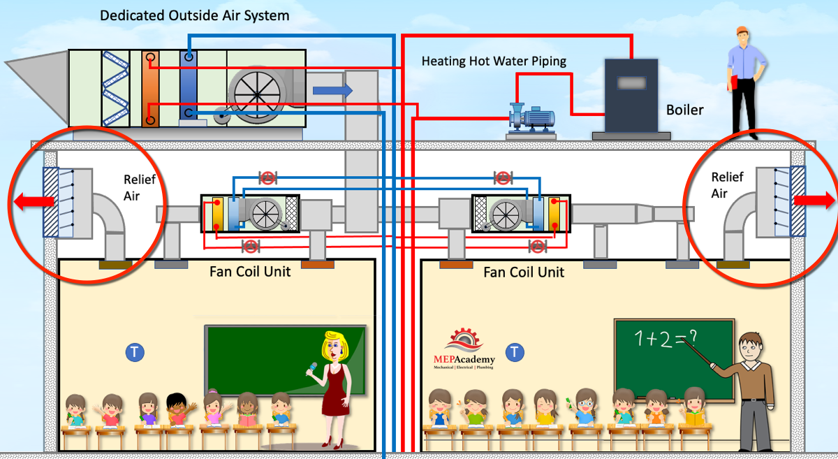
Barometric dampers are used on small systems, such as a classroom as shown here. When the classroom becomes over-pressurized, the barometric damper opens without the assistance of electrical power.
Economizer with Relief Fan/Powered Exhaust
Another method of relieving the building pressure caused by the economizer is to use a relief fan as shown here. When the economizer is operating the relief fan will be engaged and cycle on and off with the economizer. There has to be a method of controlling the relief fan according to the building pressure and the amount of outside air that is brought in during economizer mode, which can varying from 100% down to the minimum position according to ASHRAE 62.1.
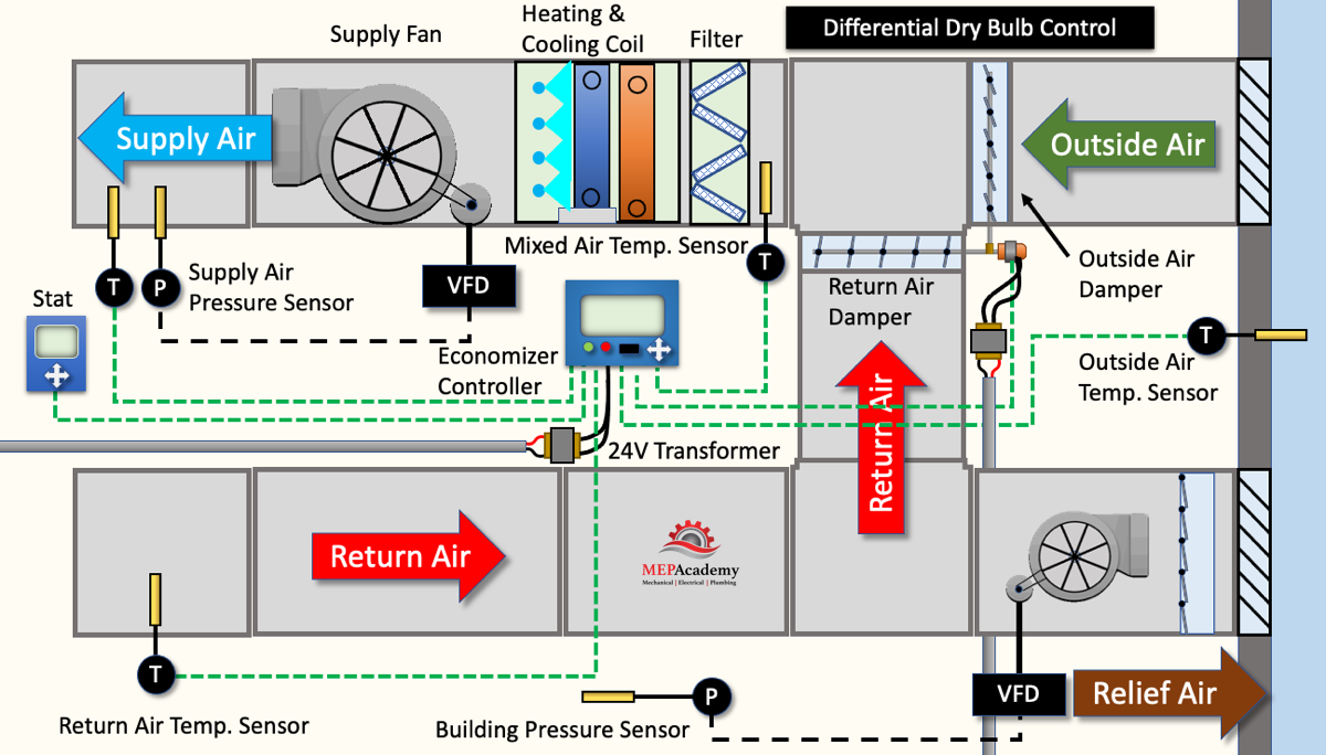
Remember that the economizer is modulating the volume of outside air that is coming into the building to meet the current demand which is fluctuating. This will require that the relief fan or fans be cable of some form of variable volume. This can occur by staging multiple relief fans in a large system, or with the use of a variable frequency drive to vary motor speed.
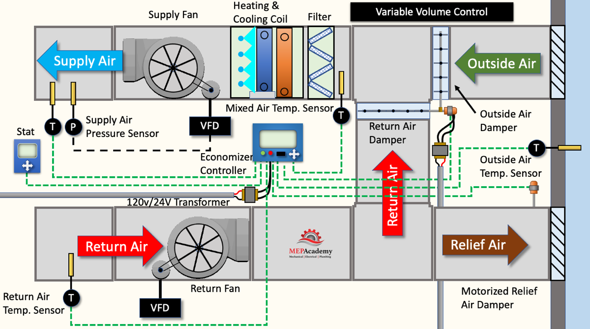
Economizer with Return Fan
The addition of a return fan is important with ducted systems that have a large pressure drop to overcome. With the addition of a return fan, the supply fan can be slightly smaller as it doesn’t need to overcome the static pressure of the return ductwork.
Controlling Economizers
Economizers can be controlled using differential dry bulb temperatures or enthalpy, which is both temperature and humidity.
Using differential dry bulb will activate the economizer when the outside air drops below the return air.
When using differential enthalpy the economizer is activated when the outside air enthalpy drops below the return air enthalpy.
We’ll use an example of a differential dry bulb economizer.
In heating mode the outside air damper is at minimum position according to ASHRAE 62.1 ventilation requirements. The minimum outside air mixes with the return air. When cooling is required and the temperature is between 35 and 55 F (2 C to 13 C) the compressor can shutoff and the outside air can mix with the return air to maintain the supply air temperature setpoint. The outside air damper will modulate from its minimum to maximum position in order to satisfy the supply air temperature setpoint.
As the outside air temperature rises further somewhere between 55 F to 75 F (13 C to 24 C), the outdoor air may not be sufficient to reach the supply air setpoint, so the mechanical system will start up and run the compressor or modulate the chilled water valve. This is considered an integrated system, one where the economizer and mechanical cooling work together to satisfy the setpoint temperature. The outside air damper is 100% open and the mechanical system modulates to reach the supply air setpoint.
The economizer will have a high-limit shutoff temperature where the economizer will reset itself to the minimum position to meet ASHRAE 62.1 for minimum ventilation. This can be 75 F (24 C) or slightly lower depending on geographical area.
ASHRAE 62.1 and (0.1 Requirements
ASHRAE 62.1 requires a minimum amount of outside air for ventilation purposes, but with the use of an economizer, outside air can be used for cooling when conditions are right and provide 100% of the air. The economizer can come as part of a packaged HVAC unit or as stand-alone components.
ASHRAE 90.1 2019 6.4.3.4 Ventilation System Controls requires that all outdoor intake and exhaust systems be equipped with motorized dampers that will automatically shut when the system or spaces served are not in use. Outdoor air and exhaust/relief dampers shall be capable of and configured to automatically shut off during preoccupancy building warm-up, cool-down, and setback, except when the supply of outdoor air reduces energy cost or when outdoor air must be supplied to meet code, except that gravity back draft dampers are acceptable for exhaust and relief in buildings less than three stories in height located in Climate Zones 0, 1, 2, and 3. This means that if your building is three stories or more than a motorized damper maybe required.