


Bypass Damper HVAC VVT System. You might be familiar with a Variable Air Volume VAV System, but we’ll explain the less energy efficient version that tries to mimic the VAV system. A Variable Volume/Variable Temperature system uses similar components to that of a VAV but is not as effective at saving energy. We’ll show you the control strategy for a commercial and residential application using a Bypass Damper.
If you prefer to watch the Video of this presentation, then scroll to the bottom or click this link. Bypass Damper HVAC VVT System
Commercial VVT System with Bypass Damper
The constant volume air conditioner or heat pump serves several zones, with each zone having their own zone damper and controller. When the zone dampers start to close the static pressure sensor picks up an increase in the duct static pressure and sends a signal to the bypass damper controller to modulate the damper open.
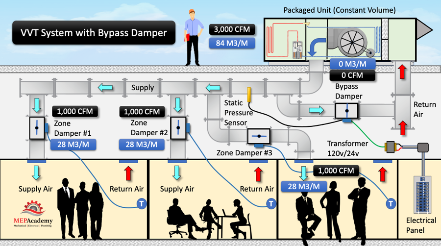
If we look at an example using a 3,000 CFM (84 M3/M) constant volume air conditioner with three zones each sized for 1,000 CFM (28 M3/M) at peak load, and with a Bypass Damper that is closed because all of the Air Conditioners air is being delivered to the zones.
If the controller for Zone Damper #1 required less air and the damper modulated down to deliver only 500 CFM (14 M3/M), then only 2,500 CFM (70 M3/M) of the total air from the air conditioner is needed by the zones.
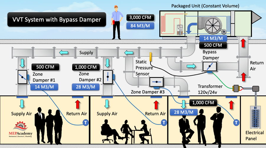
As the Zone Damper #1 modulates to partially closed, the pressure in the supply duct will increase. This increase in duct pressure will be picked up by the Static Pressure Sensor which will send a signal to the Bypass Damper controller to modulate open to allow the excessive air, in this case 500 CFM (14 M3/M) to pass from the supply air to the return air duct without entering any of the zones as shown above.

If Zone Damper #2 was to also reduce the amount of air delivered to the space in the same amount, then the duct pressure would increase and the static pressure sensor would send a signal to the Bypass Damper to open further.
Then if Zone Damper #1 closes completely as the occupants have left the space, then the Bypass Damper will have to Bypass all the air that would have gone to this zone.
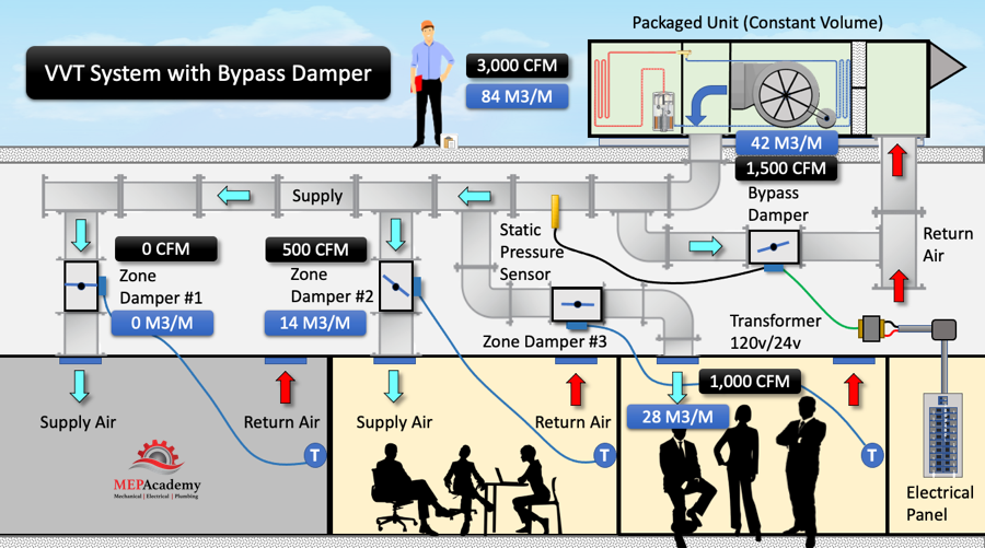
Remember that the air conditioner is a constant volume unit and has no way to reduce the air delivered by the unit. This air has to go somewhere, so it is bypassed from the supply air to the return air without entering the space. What happens is that the air becomes cooler or warmer because it hasn’t rejected or absorbed heat from the space.
Residential VVT System with Bypass Damper
Anyone that has lived in a two story home knows that its best served by two separate HVAC systems. Some have tried to modify the one Air Conditioning System by adding individual zone dampers, one for the first floor and a separate one for the second floor.
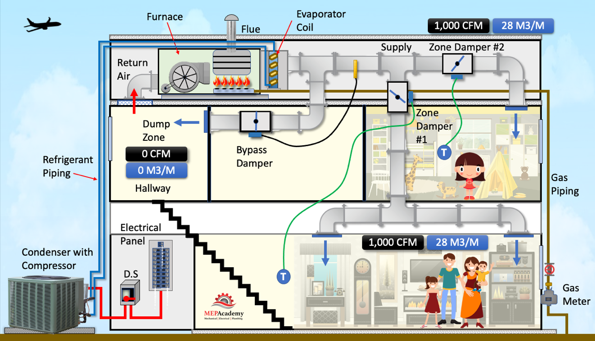
When the residents go to sleep at night on the second floor, the first floor damper can close. Since this is a constant volume air conditioner the additional air will be bypassed to the return air plenum or to a dump zone. The dump zone should be a hallway or unoccupied area of the house as the extra air dumped in this area will cause temperature problems, such as excessive heating or cooling depending on the mode of operation.
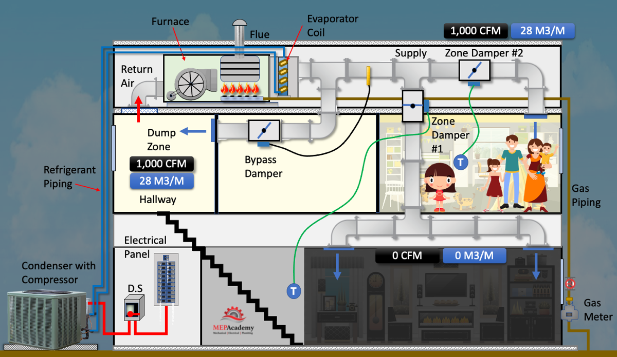
We show a motorized bypass damper in this diagram, but a barometric damper is often used. The barometric damper is set to open when the pressure increases to a certain amount, allowing air to bypass the supply and be redirected to the return.
The other way is to directly connect the bypass duct to the return duct which avoids excessive temperature swings in a dump zone. There are many variations of this installation in order to achieve some form of zoning. The best system layout would be to have two separate HVAC systems, one for the first floor and a separate one for the second floor.
VVT Controls
The installation of the controls for a VVT System with a Bypass Damper is simple compared to a standard DDC system for a VAV system. First will install zone controllers for each zone that are connected to the zone dampers using 20ga 3 wire shielded cable.
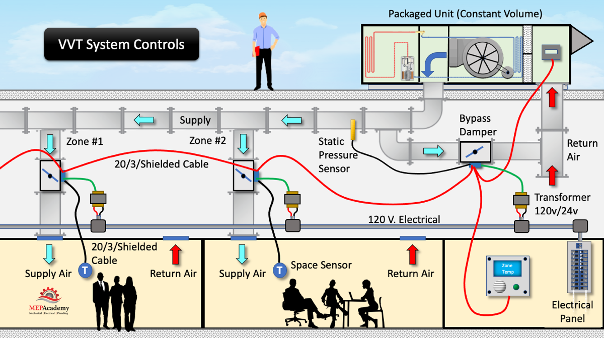
Next we need to install a 120 volt main feeder to power all the dampers. A 120v to 24v Transformer will need to be installed to power the Bypass damper, and transformers for the zone dampers. All the zone dampers can be daisy chained together using the same 20ga 3 wire shielded cable, and then connected to the Air Conditioner. A main controller can be installed that allows for reading of all the status points of the system. And lastly there will be a static pressure sensor installed. There are other optional control items that can be installed like a CO2 sensor for carbon dioxide sensing and ventilation control, heating hot water valve actuators for Zones with Heating Hot Water. The system can also be monitored by a Building Management System.
Variable Volume
A VVT system uses zone dampers so that each zone can adjust the volume of air that it receives based on its heating or cooling load. Each zone will have its own controller that will adjust the air volume to its zone based on the demand.
What makes the VVT system different from the more efficient VAV system is the use of less expensive constant volume Air Conditioning Unit and less sophisticated controls.
The VVT system uses a bypass controller to modulate the bypass damper to allow any unused supply air to return to the system. When supply air zone dampers start to close the constant volume air delivered by the air conditioner needs to be maintained by bypassing the excessive air. The Air Conditioning Unit is sized to handle the peak load, which is only needed a few times a year. The excess air needs to be bypassed and rerouted from the supply back into the return air system.
The use of a bypass damper allows for the use of the less expensive constant volume units when compared to the cost of a VAV system. The bypass damper must ensure that the constant volume unit receives the minimum amount required for it to function properly. If the minimum amount of air is not allowed over the coil, the coil could freeze up. The bypass damper also allows the ductwork to be installed using low pressure duct, as the bypass damper prevents buildup of static pressure in the ductwork. Excessive static pressure could cause the joints or seams of the duct to come apart, creating leaks.
The bypass controller uses a duct static pressure sensor installed in the supply air ductwork. The controller is set by the user to maintain a minimum and maximum pressure in the supply duct main. As the static pressure in the duct increases due to zone dampers closing, the sensor picks up an increase in static pressure and will modulate to bypass the excess air.
There are two simple setups for the bypass air, it can either be ducted directly into the return air duct, or it can be bypassed into the return air plenum if the plenum is rated and approved for this use.
Because the fan is always running at constant speed, there is no fan energy savings when the zone dampers start closing, as opposed to a true VAV system where the fan speed is reduced.
Variable Temperature
The system temperature will also vary as the bypass damper passes excessive air from the supply back to the return. This excessive bypass air is the quantity of CFM supplied by the constant volume unit that’s above what is needed by the zones at any time. As this cold air is not sent to the zones to pick up heat from the space it returns to the air conditioner cold.
Because the volume of return air is reduced due to the zone dampers partially closing, the excess cold supply air is bypassed back to the unit without picking up heat. This raises the supply air temperature, hence the variable temperature part of the system.
