


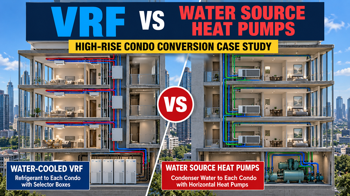
Converting an existing high-rise office building into residential condominiums creates an unusual HVAC design challenge.
An office building may have originally been designed around relatively large HVAC zones, centralized air distribution, and equipment serving an entire floor or substantial portions of a floor. Residential condominiums require something very different. Each residence needs individual temperature control, different operating schedules, appropriate ventilation, and an HVAC system that can be maintained without unnecessarily affecting neighboring residences.
In this case study, we will examine an eight-story office building being converted into residential condominiums. The existing building uses a condenser-water system with a large floor-mounted water-source heat pump serving each floor.
Rather than abandoning that infrastructure, we will compare two approaches that can potentially reuse the existing condenser-water system:
Option 1 — Water-Cooled Variable Refrigerant Flow (VRF)
Option 2 — Individual Water-Source Heat Pumps (WSHPs)
Both approaches can provide individual residential zoning. Both can use a central condenser-water loop. And both can potentially take advantage of substantial portions of the building’s existing mechanical infrastructure.
But beyond those similarities, they become very different HVAC systems.
The differences involve much more than equipment efficiency. Refrigerant distribution, condenser-water piping, ceiling space, ventilation, controls, serviceability, refrigerant concentration, central plant operation, energy consumption, and construction cost all become part of the decision.
Most importantly, when we developed a construction budget for a similar project, the difference in installed cost was significant.
And much of that difference was found not simply in the equipment, but in the distribution systems required to connect that equipment to every residence.
The Existing High-Rise HVAC System
For our case study, imagine an eight-story commercial office building being converted into residential condominiums.
The existing HVAC system consists of a large floor-mounted water-source heat pump on each floor. For purposes of our example, assume each floor originally had approximately 50 tons of cooling capacity.
The individual floor units are connected to a common condenser-water system. The building also contains the infrastructure normally associated with such a system, potentially including:
- Condenser-water supply and return risers
- Condenser-water pumps
- Fluid coolers or cooling towers
- A boiler or other means of adding heat to the loop when required
- Central plant controls
- Existing outside-air distribution
This infrastructure has substantial value.
If it is in suitable condition and has adequate capacity, reusing it may avoid replacing major portions of the central mechanical plant.
However, the original floor-by-floor zoning strategy no longer works once the office space is divided into individual residences.
Each condominium needs independent temperature control.
That is the fundamental problem our two proposed HVAC systems need to solve.
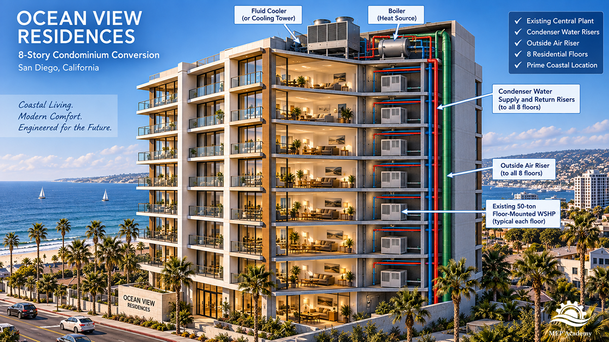
The existing office building uses large floor-mounted water-source heat pumps connected to a common condenser-water system. The office-to-condominium conversion requires replacing the original floor-level zoning with individual HVAC control for each residence.Start With the Loads, Not the Equipment
Before deciding between VRF and water-source heat pumps, an engineer needs to determine what the converted building actually requires.
Changing a building from commercial offices to residential condominiums changes many of the variables that influence heating and cooling loads.
These can include:
- Occupancy density and schedules
- Lighting loads
- Plug and appliance loads
- Outdoor-air requirements
- Exterior exposure
- Interior zoning
- Solar loads
- Operating schedules
- Kitchen and residential equipment loads
- Exhaust requirements
- Diversity between individual spaces
Each condominium therefore needs its own heating and cooling load calculation.
The engineer must also evaluate the coincident peak load for each floor and ultimately the entire building.
This leads to an important point:
Existing HVAC capacity is not the same thing as the new building load.
If the original floor-mounted heat pump was 50 tons, that does not mean the converted residential floor necessarily requires 50 tons.
The existing equipment provides useful information about the original HVAC design, but it does not establish the load for a completely different occupancy and space configuration.
New loads should be calculated based on the proposed residential use.
A useful visual sequence here is:
Individual Condominium Loads → Floor Peak Load → Building Peak Load
Once those loads have been established, we can begin evaluating the two HVAC strategies.
Option 1: Water-Cooled VRF
The first alternative is a water-cooled VRF heat-recovery system.
Most people are familiar with air-cooled VRF systems where outdoor condensing units are located on a roof or outside the building.
Water-cooled VRF works differently.
Instead of rejecting and absorbing heat directly through outdoor air, the VRF modules exchange heat with the building’s condenser-water loop.
That means the modules can often be installed indoors in mechanical rooms.
For our example, the system might consist of several modular water-cooled VRF units serving each floor. If approximately 7-ton modules were used, multiple modules could be combined to provide the required floor capacity.
The exact module arrangement would ultimately depend on the calculated loads and the selected manufacturer’s allowable equipment combinations.
This configuration creates an important opportunity in an existing building:
The existing condenser-water risers may potentially be reused.
The condenser-water system supplies the VRF modules. From there, however, the distribution system changes completely.
Instead of distributing condenser water to each residence, the VRF system distributes refrigerant.

Section view of the water-cooled VRF concept, with modular VRF equipment located in the mechanical room and refrigerant distributed to individual fan-coil units serving the condominiums.Distributing Refrigerant Throughout the Floor
From the water-cooled VRF modules, refrigerant piping travels throughout the floor.
For a heat-recovery VRF system, the refrigerant piping connects to branch or selector boxes strategically located within the building.
For our conceptual design, we considered six-port selector boxes, with each selector box potentially serving several condominium zones.
From those boxes, individual refrigerant branches continue to the indoor fan-coil units serving the residences.
This provides extremely flexible zoning.
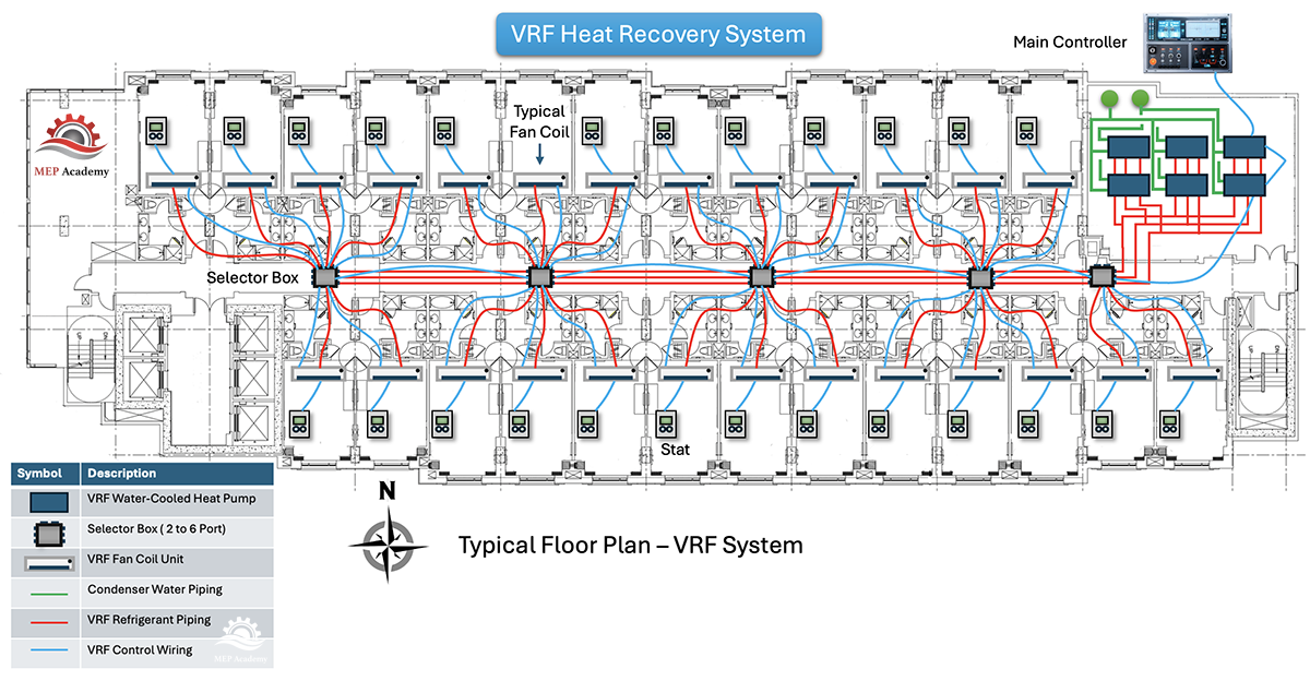
Typical floor layout for the water-cooled VRF option. Refrigerant is distributed from the VRF modules through heat-recovery selector boxes to individual fan-coil units serving each condominium.One condominium can require cooling while another requires heating.
With an appropriately designed heat-recovery VRF system, energy can potentially be transferred between zones rather than simply being rejected through the condenser-water system.
This simultaneous heating and cooling capability is one of VRF’s major attractions.
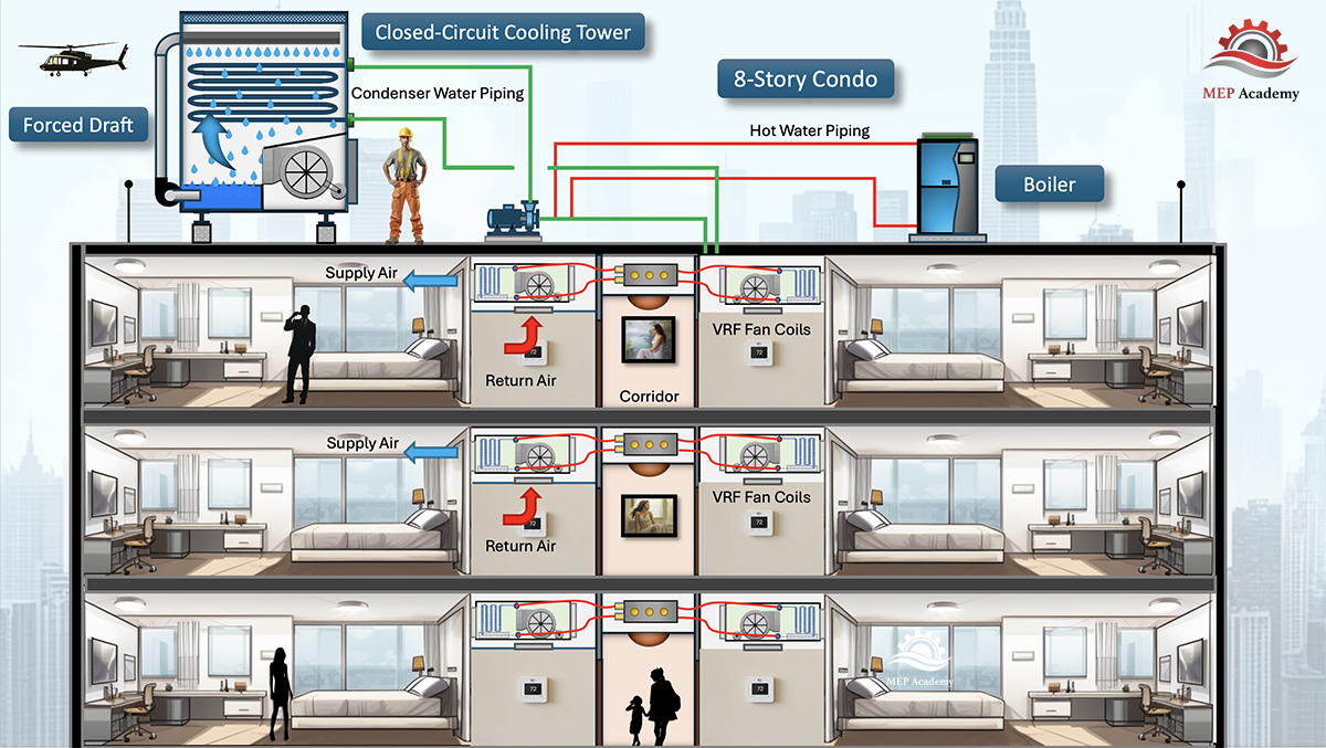
In a heat-recovery VRF system, refrigerant is distributed through corridor-mounted selector boxes to individual fan-coil units serving each condominium.The VRF Refrigerant Piping Network
The advantages of VRF come with a more sophisticated refrigerant distribution system.
Refrigerant piping must travel from the VRF modules to selector boxes and from those selector boxes to the individual indoor units.
The designer must consider factors such as:
- Refrigerant pipe sizing
- Manufacturer-specific branch fittings
- Equivalent piping length
- Maximum allowable piping lengths
- Vertical separation
- Refrigerant charge
- Oil return
- Allowable indoor-unit combinations
- Insulation
- Pipe supports
- Access to selector boxes
- Pressure testing
- Evacuation and commissioning
These requirements become particularly important in an existing high-rise.
Routing is not an abstract engineering exercise. There must physically be enough room above the ceilings to install everything.
The refrigerant piping has to coexist with plumbing, electrical conduit, cable trays, fire sprinkler piping, ventilation ductwork, structural members, and other existing utilities.
Rated wall penetrations also need to be coordinated and appropriately protected.
Selector boxes need locations that provide both piping access and sufficient service clearance.
A technically sound VRF design can become difficult or expensive if the building does not provide practical pathways for the refrigerant distribution system.
Refrigerant Quantity and Occupied Spaces
There is another important issue with VRF systems: refrigerant quantity.
A large VRF system can contain a substantial refrigerant charge, and portions of that interconnected refrigerant system serve occupied spaces.
The designer therefore needs to evaluate the applicable mechanical and refrigeration codes, the refrigerant being used, the volume of the occupied spaces, the system configuration, and the amount of refrigerant that could potentially be released into a particular space under the applicable design scenario.
This analysis can influence decisions involving:
- System zoning
- Refrigerant circuit size
- Selector-box arrangements
- Total refrigerant charge
- Leak detection
- Ventilation
- Other mitigation measures where required
This issue can become particularly important in smaller residential spaces.
A small bedroom, for example, has considerably less room volume than a large open office area.
For that reason, refrigerant concentration analysis should be incorporated into the system design process rather than performed only after the refrigerant piping layout has been completed.
The results can potentially affect the architecture of the VRF system itself.
VRF Controls
VRF is also a highly integrated controls platform.
Indoor units, selector boxes, outdoor or water-cooled modules, electronic expansion valves, sensors, and controllers communicate as part of the system.
Individual residences can have local temperature controllers while a supervisory controller provides broader system monitoring.
Where appropriate, gateways may also allow integration with a building automation system.
This provides sophisticated control, but it also means troubleshooting can require technicians familiar with:
- Refrigeration
- Electronic expansion valves
- Communication networks
- Inverter-driven compressors
- Manufacturer-specific controllers
- Diagnostic software
This should be considered when evaluating the long-term maintenance strategy for the property.
Option 2: Individual Water-Source Heat Pumps
The second alternative takes a fundamentally different approach.
Instead of distributing refrigerant throughout the floor, we distribute condenser water.
The existing large floor-mounted heat pump is removed, and the condenser-water supply and return piping is extended throughout the floor.
Each condominium receives its own horizontal water-source heat pump.
These units can often be installed above a ceiling or in another accessible service location.
Each residence now has its own:
- Compressor
- Refrigerant circuit
- Fan
- Controls
- Condenser-water connection
- Condensate connection
The refrigerant remains primarily within the individual packaged heat pump.
The distribution system outside the equipment is primarily water.
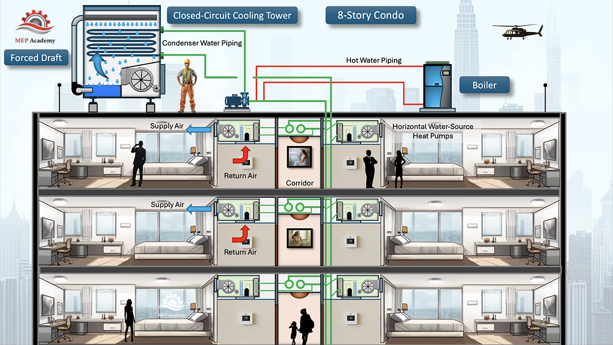
Section view of the individual water-source heat-pump concept, with each condominium served by its own heat pump connected to the building's common condenser-water loop.Condenser-Water Distribution
The existing condenser-water risers can potentially remain in service.
New horizontal supply and return mains would then extend from those risers across each floor.
Branches connect the mains to the individual heat pumps.
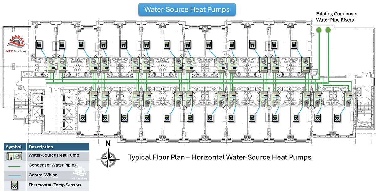
Typical floor layout for the water-source heat-pump option. Condenser-water supply and return piping is distributed throughout the floor to individual horizontal heat pumps serving each condominium.A typical installation may include components such as:
- Isolation valves
- Flow-control or balancing devices
- Strainers where required
- Flexible connections
- Control valves
- Service access
- Appropriate pipe supports
The designer must verify that the existing pumps and distribution system can accommodate the proposed flow rates and pressure requirements.
For preliminary planning, conventional water-loop heat-pump systems are often encountered around 2.5 to 3.0 GPM per ton, although actual design flow should always be based on the selected equipment and manufacturer’s performance data.
Using 3 GPM per ton as a simple conceptual example, a 50-ton connected load would represent approximately 150 GPMat full design flow.
However, the entire building does not necessarily need to operate continuously at full connected flow.
That becomes important when we discuss pumping energy.
Both Systems Still Need the Central Condenser-Water Plant
An important point in this comparison is sometimes overlooked.
Water-cooled VRF does not eliminate the condenser-water system.
Both of our alternatives rely on the building’s central condenser-water infrastructure.
Depending on the existing system and design, that may include:
- Fluid coolers or cooling towers
- Condenser-water pumps
- Supply and return risers
- Boiler or other heat-addition equipment
- Water treatment
- Central plant controls
The water-cooled VRF modules exchange heat with this loop.
The individual water-source heat pumps also exchange heat with the same loop.
Therefore, when comparing the two systems economically, we should not assign the fluid cooler and central pumps only to the water-source heat-pump option.
They are common infrastructure required by both alternatives in this case study.
Failure and Redundancy
System architecture also affects what happens when something fails.
With individual water-source heat pumps, a heat-pump failure generally affects one condominium.
The affected unit can be isolated, serviced, or replaced while neighboring residences continue operating, assuming the common condenser-water system remains available.
VRF is more interconnected.
Depending on the system architecture, a problem involving a common refrigerant circuit, selector box, communication system, or VRF module can potentially affect multiple indoor units.
Modular VRF equipment can provide some redundancy, but designers should still consider the failure domain of the system.
In a condominium building, this matters because a maintenance issue affecting several residences can be considerably more disruptive than replacing one packaged heat pump.
Serviceability
Individual water-source heat pumps are conceptually straightforward.
A typical unit has:
- Water in
- Water out
- Electrical power
- Condensate
- Supply and return air
- Local controls
Many commercial HVAC service companies are familiar with this equipment.
VRF requires a different skill set.
Technicians may need to understand inverter compressors, electronic expansion valves, refrigerant distribution, communication networks, selector boxes, sensors, and manufacturer-specific diagnostic procedures.
Neither approach is inherently unserviceable.
But the building owner should consider the availability and cost of qualified service personnel before selecting the system.
Ceiling Space: Different Problems, Not No Problems
It is tempting to assume that one option automatically solves the ceiling-space problem.
In reality, each system introduces different coordination requirements.
VRF generally uses smaller refrigerant piping compared with large condenser-water mains, which can be advantageous in congested ceiling spaces.
But VRF also introduces:
- Multiple refrigerant lines
- Insulation
- Selector boxes
- Service clearances
- Numerous branch connections
The WSHP alternative requires larger condenser-water supply and return piping.
It also requires physical space for each individual heat pump and associated valves and accessories.
So the comparison is not simply:
Small piping versus large piping.
The real question is whether the building has appropriate space for the entire distribution and equipment strategy.
Condensate Drainage
Condensate drainage is one area where the two alternatives are relatively similar.
Both VRF indoor units and horizontal water-source heat pumps produce condensate during cooling.
Because the building is being converted into condominiums, plumbing fixtures will already be distributed throughout the floor.
Where permitted by the plumbing design and applicable code, condensate can potentially be routed to nearby approved plumbing connections, such as an appropriate connection associated with a sink.
This can be considerably simpler than routing every condensate line back to a central drain riser.
There is one additional consideration with VRF.
Depending on the manufacturer and selector-box design, certain heat-recovery components may also require condensate drainage.
That requirement should be verified for the specific equipment being selected.
Overall, however, condensate drainage probably would not be the deciding factor between these two systems.
Ventilation Air and the Existing Outside-Air Riser
Neither VRF nor individual water-source heat pumps eliminates the requirement for code-compliant outdoor ventilation.
In our existing building, however, there is another potentially valuable asset: an existing outside-air riser that previously supplied ventilation air to the original floor-mounted heat pumps.
Before installing an entirely new ventilation distribution system, the engineer should investigate whether this riser can be reused.
That evaluation should include:
- Physical condition
- Riser dimensions
- Available airflow
- Available static pressure
- Existing leakage
- New residential ventilation requirements
- Proposed floor distribution
- Fire and smoke requirements
If suitable, the existing riser could potentially become part of the new ventilation strategy.
Should We Consider a DOAS?
A Dedicated Outdoor Air System, or DOAS, should also be evaluated, particularly with the VRF alternative.
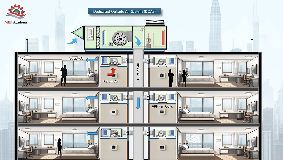
A DOAS can provide conditioned outdoor ventilation air to each condominium while the individual VRF or water-source heat-pump units handle the space heating and cooling loads.Many VRF indoor units operate with relatively high sensible heat ratios. Depending on the selected equipment and operating conditions, their latent moisture-removal capability may be limited relative to the sensible cooling load.
That becomes important in a coastal environment such as San Diego, where outdoor ventilation air can contribute meaningful latent load.
A DOAS can condition and dehumidify the ventilation air before delivering it to the residences.
This allows the individual VRF fan coils to focus primarily on the space sensible loads.
The existing outside-air riser might even be reusable as part of the DOAS distribution system if its capacity, condition, and configuration are appropriate.
The same DOAS concept can also be evaluated with water-source heat pumps. It is not exclusive to VRF.
Fire and Life-Safety Coordination
An office-to-residential conversion changes much more than HVAC zoning.
New condominium walls, corridors, shafts, and rated separations can affect mechanical distribution throughout the building.
HVAC coordination may therefore involve:
- Firestopping of piping penetrations
- Rated shaft penetrations
- Fire dampers where required
- Smoke dampers where required
- Access requirements
- Corridor construction
- Smoke-control systems where applicable
- Coordination with the building’s overall fire-life-safety design
These requirements can influence both HVAC options and should be incorporated early in the design.
Installation and Construction Phasing
Existing-building projects also require careful sequencing.
For the VRF option, construction could involve:
- Verifying existing condenser-water infrastructure.
- Establishing new mechanical-room locations.
- Installing the water-cooled VRF modules.
- Installing refrigerant mains.
- Installing selector boxes.
- Running branches to individual residences.
- Installing fan coils.
- Coordinating condensate, power, controls, and ventilation.
- Pressure testing and evacuating the refrigerant piping.
- Charging and commissioning the system.
The WSHP option would follow a different sequence:
- Verify the existing condenser-water system.
- Extend new supply and return mains throughout each floor.
- Install branches to each residence.
- Set the individual heat pumps.
- Connect water, ductwork, condensate, electrical power, and controls.
- Flush the piping system.
- Balance and verify flow.
- Commission the equipment.
The best solution may therefore depend partly on how the renovation is phased and how easily each distribution system can be installed within the existing structure.
What About Energy Consumption?
A simple statement that either VRF or WSHP is always more energy efficient would overlook how these systems actually operate.
Water-cooled VRF has several potential advantages.
Inverter-driven compressors can modulate capacity to match changing loads. Heat-recovery configurations can also transfer energy between zones when some residences require cooling while others require heating.
But the WSHP system has significant part-load opportunities of its own.
One important strategy is to install two-way control valves at the individual heat pumps.
When a heat pump does not require condenser-water flow, its valve can close.
As more units cycle off or require less operation, total condenser-water flow decreases.
If the central condenser-water pumps are equipped with variable-frequency drives, the pumps can respond to the reduced system demand by slowing down.
That can substantially reduce pumping energy during part-load operation.
The common water loop can also facilitate heat exchange within the building. Heat rejected into the loop by residences in cooling can help satisfy heat required by residences operating in heating before the central plant has to add or reject additional energy.
Therefore, both systems can have strong part-load strategies.
Determining which system uses less energy requires analysis of the complete building, including:
- Equipment efficiencies
- Load profiles
- Condenser-water temperatures
- Pumping strategy
- Heat-rejection equipment
- Heating requirements
- Controls
- Climate
- Simultaneous heating and cooling
- Building diversity
A building energy model would provide a much better answer than relying solely on generalized equipment-efficiency claims.
What Happened When We Priced the Two Systems?
This was one of the most interesting parts of our comparison.
On paper, water-cooled VRF was an attractive solution.
It offered individual zoning, modular equipment, sophisticated controls, heat recovery, and relatively compact refrigerant piping.
But when we developed an actual construction budget for a similar conversion, the VRF option was substantially more expensive than the individual water-source heat-pump approach.
Why?
A major reason was the distribution system.
The Cost of VRF Refrigerant Distribution
A high-rise VRF system requires a substantial network of refrigerant piping.
That network can include:
- Large refrigerant mains
- Horizontal refrigerant distribution
- Vertical risers where applicable
- Multiple pipe sizes
- Manufacturer-specific branch fittings
- Selector boxes
- Refrigerant branches to every indoor unit
- Pipe supports
- Required insulation
- Controls and communication wiring
- Specialized installation procedures
- Refrigerant pressure testing
- Evacuation
- Charging
- Manufacturer-specific commissioning
None of those items is particularly surprising individually.
The issue is scale.
Repeat them across every condominium and every floor of a high-rise building, and the cost accumulates quickly.
Copper refrigerant piping is also a relatively expensive distribution medium, and the labor associated with installing, brazing, supporting, insulating, testing, evacuating, and commissioning a large refrigerant network can be substantial.
Why the WSHP Distribution System Was Less Expensive
The individual water-source heat-pump alternative still requires significant piping.
Each residence needs condenser-water supply and return connections along with valves, flow-control components, supports, and other hydronic accessories.
But this is fundamentally conventional hydronic distribution.
At typical condenser-water loop operating temperatures, this piping also may not require the same thermal insulation treatment as applicable VRF refrigerant lines, subject to the governing energy code, operating temperatures, condensation considerations, and project-specific requirements.
The WSHP design also eliminates the floor-wide refrigerant distribution network, VRF selector boxes, and much of the specialized refrigerant hardware connecting multiple residences.
The individual heat pumps still have refrigerant circuits, but those circuits are largely contained inside the packaged equipment.
That distinction had a meaningful impact on our construction budget.
First Cost Versus Life-Cycle Cost
Our construction budget showed a significant first-cost advantage for the individual water-source heat-pump system.
But first cost is not the entire economic analysis.
A complete life-cycle evaluation should also consider:
- Annual energy consumption
- Pumping energy
- Central plant energy
- Maintenance
- Water treatment
- Refrigerant service
- Controls maintenance
- Equipment replacement
- Equipment life expectancy
- Availability of replacement parts
- Service labor
- Future refrigerant requirements
Both systems offer opportunities for efficient part-load operation.
Therefore, determining the true life-cycle cost requires evaluating expenses over the expected life of the building rather than simply comparing construction bids.
For this project, however, first cost clearly favored the individual WSHP approach.
So Which System Would We Choose?
Both systems can work for this type of conversion.
Water-cooled VRF provides excellent zoning, modulation, and heat-recovery capabilities.
But based on our actual construction budget, the individual water-source heat-pump system had a significant first-cost advantage.
It also keeps the refrigerant primarily contained within each individual unit and provides relatively straightforward service and replacement at the condominium level.
VRF remains an attractive technology, but on this particular project, its advantages came with a substantially higher installed cost.
Ultimately, the appropriate choice depends on the building, available ceiling space, existing infrastructure, maintenance strategy, code requirements, energy goals, and project budget.
For this case study, the individual water-source heat-pump system made the stronger economic case.
The Bigger Lesson: Evaluate the Distribution System
Perhaps the most important lesson from this case study is that HVAC system selection should not be reduced to comparing equipment efficiencies or manufacturers’ brochures.
In a high-rise retrofit, the equipment may represent only part of the challenge.
The building must accommodate everything that connects that equipment together.
For water-cooled VRF, that means examining the complete refrigerant distribution network.
For individual water-source heat pumps, it means examining the condenser-water distribution system.
The designer needs to ask:
Can we physically route it?
How do we maintain it?
Can we isolate failures?
Will we be able to comply with the applicable refrigerant and life-safety requirements?
Can the existing central plant support it?
How will it operate at part load?
And what will the complete installed system actually cost?
Those questions often tell us more about the suitability of an HVAC system than the equipment efficiency rating alone.
When converting an existing office building into residential condominiums, the best HVAC solution is not necessarily the system with the newest technology.
It is the system that can be integrated into the existing building economically, operated efficiently, serviced effectively, and relied upon to provide comfortable conditions for the people who will live there for years to come.