Home Blog Page 47

Centrifugal Pump Basics | How they work with VFD’s in HVAC Systems

We’ll learn centrifugal pump basics and how they work with VFD’s in HVAC Systems.

Scroll to the bottom to watch the YouTube video of this presentation.

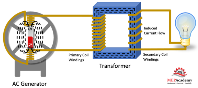
The pump is made to put energy into water by increasing the pressure or flow. The energy is transferred from the motor to the shaft then to the impellor and the water. The centrifugal force causes the water to fly outward from the impellor.

Remember according to the first law of thermodynamics, energy can’t be created or destroyed but only transferred from one location to another or converted to and from other forms of energy.

There are many factors in the proper operation of a centrifugal pump system, including the quantity or GPM (LPS) of fluid flow, piping design and layout, method of control, and the selection of the pump.

As the head decreases, the flow rate will increase, and vice verses, if the head increases, the flow rate will decrease. Pump charts are based around these two factors, flow rate and head. See our video on How to Read Pump Charts.

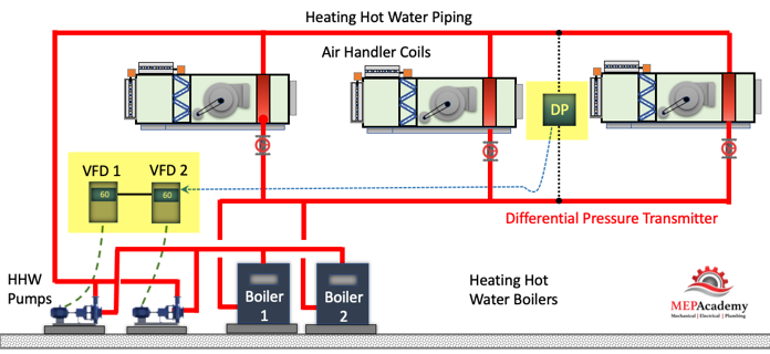
Variable Frequency Drive (VFD) Pump Control

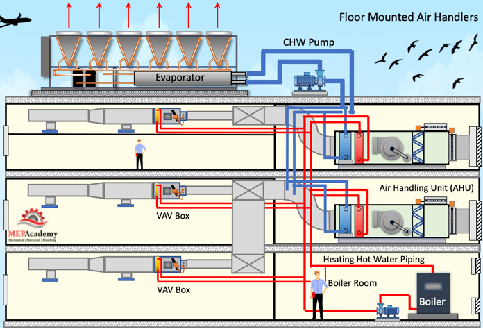
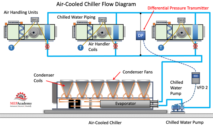
We can change the volume by speeding up or slowing down the motor using a variable frequency drive (VFD). We do this to match the load and save energy. No need for the pump to run at full speed if all that flow or GPM is not required by the air handlers or fan coils.

Centrifugal pump basics and how they work with VFD's in HVAC Systems
Centrifugal Pump basics and how they work with VFD’s in HVAC Systems

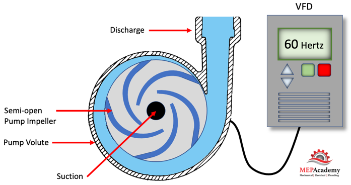
Most existing systems requiring flow control make use of bypass lines, throttling valves, or pump speed adjustments. The most efficient of these is pump speed control. When a pump’s speed is reduced, less energy is imparted to the fluid and less energy needs to be throttled or bypassed. Speed can be controlled in a number of ways, with the most popular type of variable speed drive (VSD) being the variable frequency drive (VFD).

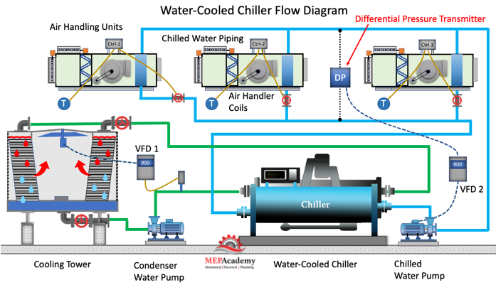
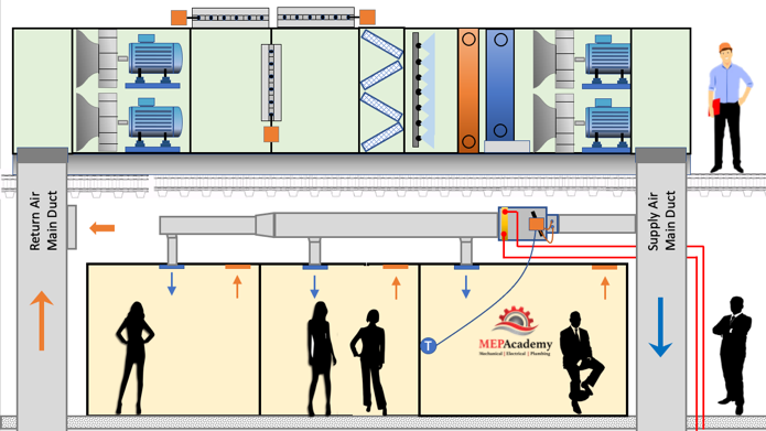
A differential Pressure Transmitter will send a signal to the VFD controlling the pump to either speed up or slow down based on the demand of the system.

Controlling Pumps using a Variable Frequency Drive (VFD)

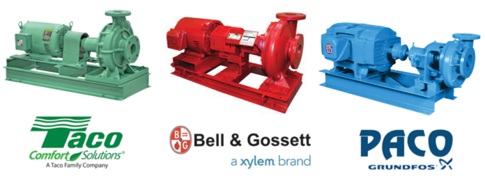
What does a HVAC Centrifugal Pump Look Like?

There are many manufacturers that make centrifugal pumps for the HVAC industry, but basically, they all function the same way and with the same purpose in mind, and that is to move a fluid through pipes and equipment while overcoming the friction. All though the colors may vary by manufacture the parts are similar.

Pump Manufactures and Color Branding

Centrifugal pumps have few moving parts with minimal wear during normal operations. There are two main components, the motor which drives the pump, and the pump which contains the impellor, the propulsion vanes that pull and push the fluid. The motor takes electrical power and converts it into mechanical energy that moves the fluid through the pipe and equipment. The pump has an inlet where it sucks in the fluid and an outlet where it pushes the fluid out through the system.

Parts of a Centrifugal Pump

Pumps are relatively a simple piece of equipment when compared to other HVAC equipment. Starting with the motor we have the motor casing which is rated for various duties, such as Open Drip Proof (ODP), Totally Enclosed Fan Cooled (TEFC). Motors can also be inverter duty rated so that a Variable Frequency Drive (VFD) can vary the speed of the motor to match the load.

End Suction Pump Parts

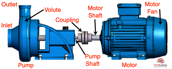
The motor has a shaft that extends into the pump portion where it attaches to the impeller, this can be a direct connection or by a coupling. The impeller is made up of vanes that rotate to impart energy to the water. The spinning vanes create a centrifugal force throwing the water from the rotating impeller. The water discharged by the impeller is thrown by centrifugal force into the spiral-shaped volute which is the housing surrounding the impeller.

Pumps are available with various impeller sizes; each size provides a different amount of flow and head. The pump may come with the option of an 7″, 7-1/2″, 8”, 8-1/2″, 9”, and 9-1/2″” impeller.

End Suction Pump Impeller Size Options

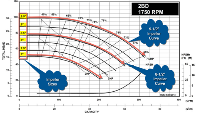
To change the flow rate of an existing pump you can trim the impeller to make it smaller or replace the impeller with a larger one if the pump isn’t already using the largest impeller for that pump model.

Disassembling the pump, we see that the motor has a fan to keep it cool when running. The motor converts electrical energy into mechanical energy and spins the shaft. See our video on how Motors Work. Attached to the shaft is an impeller which is housed inside a Volute, the protective casing surrounding the impeller, and which acts as a guide for the water being forced out of the impeller by the spinning centrifugal force.

Pump Disassembled
Pump Disassembled

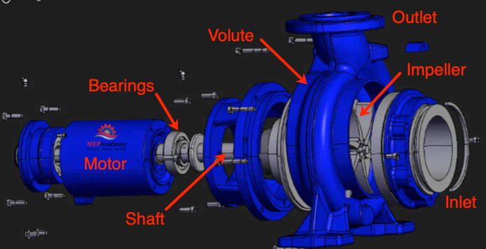
Some shafts extend all the way from the motor through the impeller, while other pumps use a coupling to match up the motor shaft with the impeller/pump shaft.  Two separate shafts meeting with a coupling that attaches them together.

The shaft passes into the pump casing and is usually made of stainless steel or high carbon steel. The shaft is support by bearings.

Impellers come in various configurations including closed, semi-open and open. The impeller shown here is of the semi-open type, which means it has as shroud on the back side only.

Impeller Types - Closed, Semi-Open and Open
Impeller Types – Closed, Semi-Open and Open

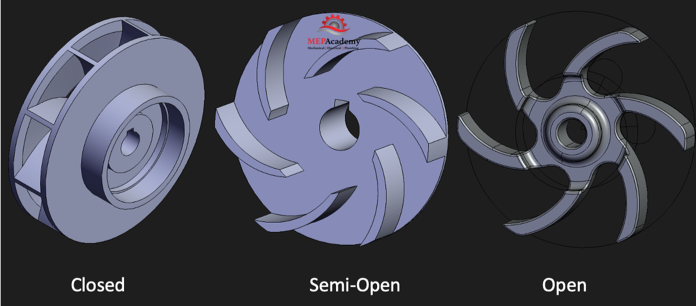
If you missed our previous video on Pump Charts, check that video out to see how Impellers are chosen to meet system design conditions.

The outer casing of the pump is called the volute and directs the water exiting the impeller to the outlet.

The stuffing box contains either a mechanical seal or packing to prevent the leakage of water from around the shaft. The packing is made of fiber and lubricated with graphite or Teflon.

With the impeller surrounded by water, and the impeller rotating, the water gets thrown outwards in all directions. The water leaving the impeller encounters the volute, while creating a lower pressure region at the suction inlet where more water is sucked in.

The discharge pressure will be higher than the suction pressure, causing the fluid to flow around the system.

Cavitation

Cavitation occurs when vapor bubbles appear due to the liquid falling below its vapor pressure. When the pressure at the inlet of the pump drops below the vapor pressure of the water, bubbles will begin to appear around the eye of the impeller. Then when these bubbles encounter a pressure above the vapor pressure of the water, the bubbles will collapse causing a crackling noise, vibration, and shock waves that can damage the surface of the impeller.

Where are Centrifugal Pumps used?

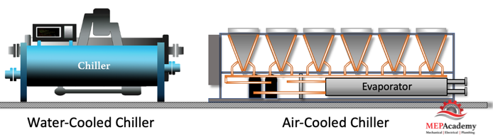
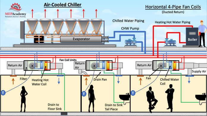
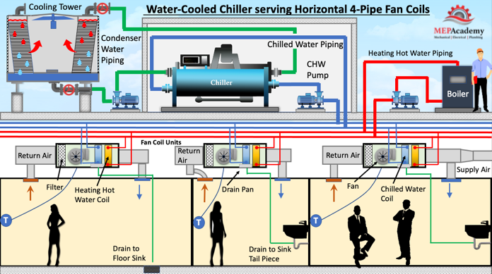
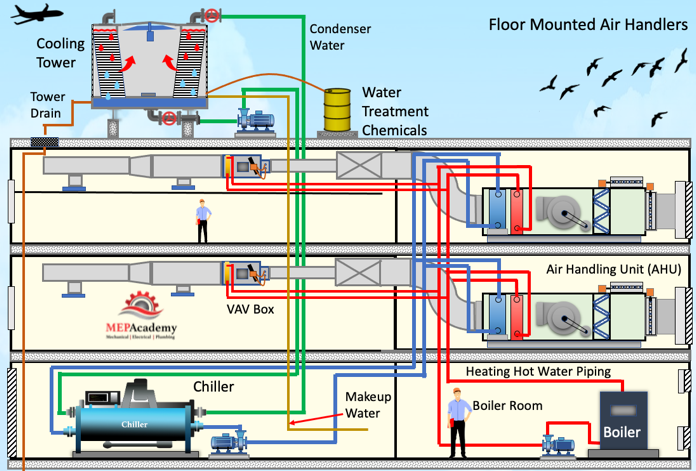
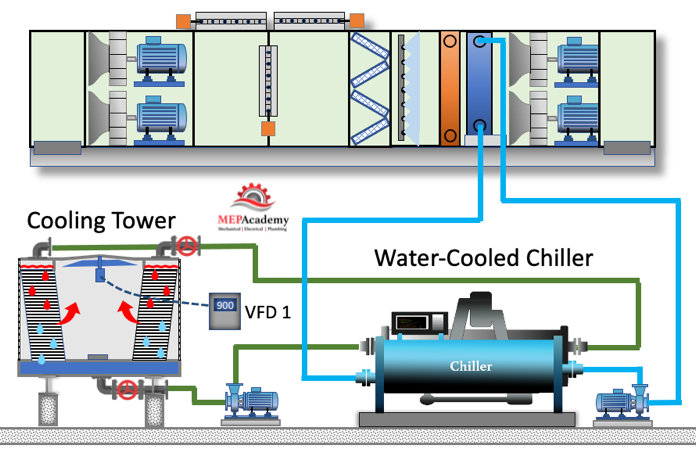
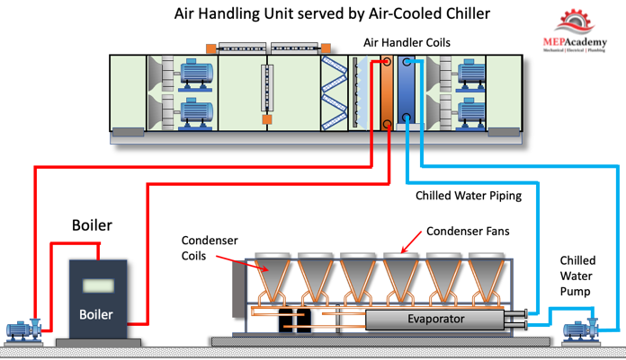
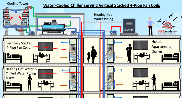
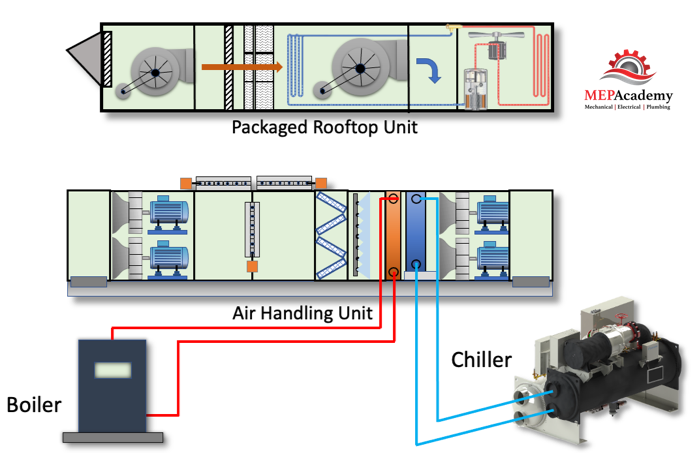
Centrifugal pumps are used mostly in the commercial HVAC industry to move chilled water, heating hot water and condenser water.

Pumps used in HVAC Systems for Condenser Water, Chilled Water, and Heating Hot Water Systems

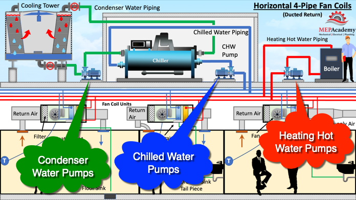
There are chilled water and heating water systems that may be comprised of primary and secondary pumps. Condenser water system that feed a cooling tower or a water-cooled heat pump system.

Small vertical inline pumps can be used in residential projects for domestic hot water recirculation and snow melt systems.

Pump Configurations

Centrifugal pumps can be provided in various configurations from end suction, split-case and vertical turbines. The most common in the HVAC industry is the end suction pump which has the inlet centered on the eye of the impeller. They are classified as either close-coupled or frame mounted.

Centrifugal Pumps and How they Work with VFD’s

Chillers and Air Handling Units

In this presentation we’ll learn how Chillers and Air Handling Units (AHU’s) work together in commercial buildings. We’ll discuss the basic functions of these systems and the advantages and disadvantages of air-cooled versus water-cooled chillers.

For the YouTube video Presentation of this, scroll to the bottom.

Air-Cooled and Water-Cooled Chillers

Chillers provide the source of the chilled water that feeds the cooling coil within the air handling unit and fan coils. Supply Air will blow over the chilled water coil in the AHU or FCU to provide cool air to the spaces in the building. The chilled water coil absorbs the heat from the air passes over them and takes the heat back to the chiller where it will be rejected to the outside.

The two most common types of chillers are air-cooled and water-cooled. This refers to the method by which the chiller ejects the heat from the system. 

Air-Cooled Chiller vs Water-cooled Chiller. Image of two types of chillers.
Water-Cooled and Air-Cooled Chiller

With a packaged air conditioning unit, the room air passes directly over a coil filled with refrigerant, while in a chilled water system the room air passes over a coil filled with chilled water.

Water-cooled chillers are manufactured in larger tonnages than air-cooled. Some manufactures make water-cooled to 6,000 tons (20,500 kW), and their air-cooled versions to 600 tons (1,900 kW).

Air-Cooled Chiller vs Water-Cooled Chiller

An air-cooled chiller uses fans to reject the heat outdoors, while a water-cooled chiller will require a cooling tower that sends water to the chiller to absorb the unwanted heat, and then eject that heat through the tower process.

Air-cooled chiller serving horizontal fan coils
Roof mounted Air-cooled chiller serving horizontal fan coils

An air-cooled chiller comes as a packaged unit from the factory including the compressor, evaporator and condenser, with the option of having chilled water pumps integrated. The water-cooled chiller needs a lot more equipment including the cooling tower, water treatment, drain lines and some form of sand or centrifugal filter. This causes air-cooled chillers to have a lower installed cost, simpler installation, lower cost for maintenance due to less components and no water issues or chemicals to deal with.

The water-cooled chiller will usually be more energy efficient, due to the fact that the compressor will have to do less work because water-cooled chillers have lower condensing water temperatures and pressures. Water-cooled chiller usually have a longer equipment life because they’re mostly installed indoors, while air-cooled chillers sit outdoors exposed to the elements. Water-cooled chillers have a life expectancy of 20 to 30 years, while air-cooled chillers is around 15 to 20 years.

Roof mounted Water-Cooled Chiller serving Horizontal 4-pipe Fan Coil Units (Image)
Roof mounted Water-Cooled Chiller serving Horizontal 4-pipe Fan Coil Units

If the HVAC contractor installs an air-cooled chiller on the roof of a building with horizontal fan coils, then installs the piping and pump, the systems is complete except for electrical power and controls.

Using the same building, If the HVAC contractor were to install a Water-cooled chiller and space wasn’t available on the ground level, a penthouse might need to be built on the roof to house the chiller, while additional structural reinforcement of the roof might be required for the weight of the cooling tower full of water.

Water-cooled chillers need a cooling tower, and the tower requires makeup water and a drain. Also some form of chemical treatment will be required for the tower water to remain stable and avoid corrosive buildup. 

With an air-cooled chiller you have no cooling tower. The installation is much easier, and it avoids the additional use of water and chemicals. If water is expensive and energy is cheap, than an air-cooled chiller might be the best option. If energy is expensive and water is cheap than the water-cooled chiller may provide the best solution.

Air-Cooled Chiller serving Air Handling Units

Here are chillers feeding air handling units and the difference between an air-cooled and water-cooled installation in the same building.

Using an air-cooled chiller can free up valuable space within a building that would otherwise be required for an water-cooled chiller. This additional space can be rented out, increasing the value of the building.

Ground floor installed Water-Cooled Chiller serving Air Handling Units

Water-cooled chillers are mostly installed indoors. This is one of the factors that leads to a longer equipment life, in the range of 20 to 30 years, as compared to an air-cooled chiller which spends all of its life outdoors and operates at a higher condenser fluid temperature. Air-cooled chillers can have a life time duration of 15 to 20 years. 

Air-cooled chillers will have lower maintenance cost due to less components, and the fact that cooling towers used in water-cooled systems need water treatment and the chiller needs condenser tube cleaning.

This leaves air-cooled chillers less expensive to install and maintain, while water-cooled systems are more energy efficient.

Water-Cooled Chillers

Water-cooled chillers can be located anywhere in the building or on the roof in a mechanical penthouse. The chiller shouldn’t be located in the basement unless access is provided for replacement. Locating the chiller on the ground floor with a removal louver or large roll up door allows for easy replacement and access for tube pulls. 

Water-Cooled Chiller serving an Air Handling Unit

The chiller will need to be connected to a cooling tower for its heat rejection. This is an extra set of pipes leaving the chiller and connecting to the cooling tower outdoors. Cooling towers are mostly installed at ground level or on the roof.

The Chilled water from the chiller is circulated around the building with the use of Chilled Water Pumps. The chilled water will circulate to all the equipment requiring cooling, which includes Air Handlers, Fan Coils and Blower Coils.

As air from the rooms in the building pass over the chilled water coils, the heat will be absorbed by the chilled water circulating through the coils in this equipment.

The heat circulates from the room through the chilled water to the water-cooled chiller where the heat is transferred into the refrigerant circuit within the chiller. The refrigerant circuit moves this heat from the evaporator to the compressor where it is compressed from a low-pressure gas to a high-pressure gas in the condenser.

Water from the cooling tower will circulate through the water-cooled condenser of the chiller and absorb this heat causing the high-pressure gas to condense and turn into high pressure liquid.

The cooling tower water has now absorbed this heat and then rejects it to the atmosphere. (See our video on the explanation on how Cooling Towers work).

Air-Cooled Chillers

Air-cooled chillers are limited in size by some energy codes as they’re considered less energy efficient than water-cooled chillers. The air-cooled chiller rejects the heat absorbed from the building by blowing air from a fan over refrigerant circulating in the condenser coils. 

Air-Cooled Chiller serving an Air Handling Unit with Hot Water Coil

Air-cooled chillers are available from as small as 10-tons to as large as 600-tons. Air-cooled chillers can be order with factory installed pumps that can save on installation time.

When looking at aerial videos or images of buildings you can spot air-cooled chillers, as they’ll have a row of fans along the complete top of the chiller used for heat rejection.

Air-Cooled chillers can be ground mounted if there is space available. Consideration needs to be made for the noise generated by the condenser fans.

Water-Cooled Chiller Control Sequence of Operation

So, here’s a simple explanation of a control sequence working with the chiller, in this case the water-cooled chiller and cooling tower. Actual sequences of control can be very elaborate with the goal of optimizing energy efficiency included in the algorithms.

Water-Cooled Chiller and Cooling Tower serving Air Handling Units

You may have a temperature sensor in the room asking for more cooling or less cooling. It’ll send a signal to the air handler controller, the controller will send an output signal to the 2-way control valve to open or close, and then the differential pressure transmitter will pick up those changes and send output signal to the VFD, which will either speed up or slow down the chilled water pump, increasing or decreasing the flow of chilled water based on the demand. 

On the condenser water side you could have a temperature sensor in the condenser water supply piping, sensing the temperature. If the water is getting too cold because the chiller demand is low, than the fan will be adjusted to a lower speed, and that’s how it works with the chiller to optimize the tower. 

Air-Cooled Chiller Control Sequence of Operation

The air-cooled chiller setup similar, but it doesn’t have to worry about the cooling tower. So, once again the temperature sensor in this space will send and input signal to the controller, and the controller will send an output signal to the 2-way control valve, whether to open or close, based on whether it needs more chilled water or less.

Air-Cooled Chiller Flow Diagram and Controls Sequence of Operation

The differential pressure transmitter of course will sense that buildup of pressure if these valves are all closing, an this pump is still pumping at the same speed, this pressure is going to build up and that differential pressure will be set to reduce the speed because the pressure is increasing too much, which means the demand has dropped off, so it can save on the pump energy by reducing its speed. 

Air Handling Units

The air handling unit has a chilled water coil and a fan that blows air over the cold coil before delivering it to the space. These differ from the Rooftop units that have the complete refrigerant circuit housed within the equipment. Air handling units cool the air by passing the warm room air over a coil that has chilled water circulating through it. The heat is absorbed by chilled water, whereas the rooftop units room air will be cooled by refrigerant circulating through the indoor coil.

See our video on Rooftop Units and our other video on Air Handling Units for a better understanding of these two systems.

The Air Handler will also use heating hot water or steam to heat the building, while the rooftop unit maybe a heat pump which uses a reverse refrigerant cycle for heating, or it may contain a gas furnace. Hot water or steam from a boiler will be sent to the air handlers heating coil to transfer heat from the coil to the room air passing over the coil.

Air handlers are available in much larger sizes than rooftop units, with custom air handlers up to 400,000 CFM.

Air handlers can be roof mounted or sit in a mechanical room on any floor in the building. Often many air handlers will serve a large building being scattered throughout the building, or one dedicated per floor, or one unit may serve the complete building. One of the main decisions is where to locate the air handling units while allowing space for sheet metal ductwork throughout the building to provide fresh air, relief air, return air and supply air.

Fan Coils and Blower Coils

Fan coils and blower coils are used for smaller spaces than what an air handling unit can cover. Fan coils can be horizontal hung or vertically stacked such as used in hotels. See our video on Fan Coils for a better understanding of these systems.

The fan coil is a miniature version of an air handler, but much less sophisticated and with fewer options. Fan coils serve much smaller areas than air handlers, and are manufactured with air volumes up to 4,000 CFM

Water-Cooled Chiller with Cooling Tower serving Vertically Stacked Fan Coil Units

Fan coils are dedicated to a single zone, while air handling units can serve a single zone to a large quantity of zones. Another difference is that outside air or ventilation air is often provided by a separate system for the fan coil unit, while the air handling unit provides its own outside air. The fan coils are often not sized to handle the load for the ventilation requirements. 

Some of the fan coils lack the capacity to handle better filtration options such as HEPA filters, UV Lighting or MERV 13 filters, this is due to lack of physical space or fan static pressure limits. 

Often the fan coil is located in or above the room in the ceiling space which can cause the occupants to hear some fan noise. The air handler is located remotely so fan noise shouldn’t be an issue.

The fan coil can be constant or variable volume, using constant volume the fan coil can adjust the leaving air temperature, while with a VAV fan coil, the volume of air will be adjusted to meet the space temperature requirements.

Heat Recovery Chillers

With the focus on energy efficiency some chillers have the option of recovering the some of the heat that is normally rejected to the atmosphere. This recovered heat can be used for pre-heating of various systems.

Chillers and Air Handlers

Air Handling Units

Air Handling Units. How they work and how they’re built.

In this presentation we’ll be learning how Air Handling Unit (AHU) works within various commercial and healthcare buildings. We’ll show you how custom Air Handling Units are built with the selection of various options such as humidifiers, heat wheels, heating and cooling coils, dampers, economizers, UV lighting and the various types of fans being used.

We’ll explain the different types of air handlers used including VAV, CAV, Dual-Duct, Multizone and 100% Outside air units.

For the YouTube video of this presentation, scroll to the bottom.

The Basic Air Handling Unit Configuration

The main differences between an air handling unit and your typical air conditioner is that the air handler doesn’t provide the source for heating or cooling. Also, air handlers are available in much larger sizes up to and over 400,000 CFM . Air handling units also allow greater customization to fit project specifics. 

Air Handling Unit vs Packaged Air Conditioner

The air conditioner has the refrigeration cycle as part of the equipment, where the compressor circulates the refrigerant that does the cooling and/or the heating. The air handling unit will do its cooling using chilled water from a chiller or refrigerant from a remotely located compressor, and do its heating using heating hot water or steam from a boiler.

Air Handling Unit Flow Diagram

As you can see the Return air system has two options, it can return air back to the inlet of the supply, or it can exhaust the air outside. The rest of the air systems only have one option as shown by the directional arrows.

How to Build a Custom Air Handling Unit

Let’s build a custom air handler like the manufacture would using the engineers project requirements and the available air handler sections. 

The air handling unit manufacture will use their software program to assemble a unit based on the project specifics. Looking at a screen of options the air handlers engineering team will start building the air handler maybe starting with the inlet options.

AHU Air Handling Unit Options image
Options available for a Custom Air Handler

We’ll build our air handling unit using plenum fans because they provide better acoustics and allow for some redundancy incase a fan burns out. As you can see we added them on the supply inlet and on the exhaust.

Since this is an operating room will add a UV (Ultraviolet) lighting system to kill any bacterial, viral or fungal organism in the air and on or near the cooling coil, including the drain pan where water accumulates before draining.

100% Outside Air Handling Unit with 100% Exhaust Air Image
100% Outside Air Handling Unit with 100% Exhaust Air.

We added an energy recovery wheel to save energy and capture the heat that is being wasted. Using 100% outside air is energy intensive as we are spending energy to cool the air and then we are exhaust all of that air out of the building. To capture this energy there are several choices like the heat recovery wheel, heat exchanger or a run around coil. We’ll explain these in another video. We also added filters on the exhaust stream to keep the energy wheel clean.

100% Outside Air Handling Unit

The first section will be our pre filter section to clean the air that’s coming in, and then the Heat Recovery Wheel, then our supply fans. The fans are what pull the air from the outdoors and push the air into the operating room. Then we’ll have a hot water and chilled water coil to temper the air, the UV Lighting system, and finally we’ll have a HEPA filter to clean the air as there’s additional requirements for the operating room, since you’re cutting people open the air has to be super clean. And then on the exhaust side we need an exhaust damper and an exhaust fan to take the air from the room and exhaust it out. 

Operating Room Air Handling Unit Image
Air Handling Unit using 100% Outside Air

Now we’ll take this air handler that we’ve built and put it in the mechanical room in the hospital. You see we got our two operating rooms. We’ll set our Air Handler that we just built, and then the HVAC contractor will run the main ducts,  exhaust and supply mains, and from there they’ll tie into branches through exhaust and supply valves feeding the operating room with laminar Flow grilles and low return. 

Then the contractor will rig and set in a boiler, hook up all the hot water piping to the hot water coil, and then make a connection from the chiller to the chilled water coil, or if you’re using a compressor you can run DX refrigerant piping. 

We just showed you how you can customize any air handler according to the project requirements, now we’ll show you a few more systems where air handlers are used.

Dual Duct Air Handling Unit

This is a dual duct air handling unit that provides Cold air and warm air to travel down two different main supply ducts to dual-duct VAV mixing boxes. After the Dual Duct mixing box the air leaves in one common duct with the correct mixture of cold and warm air to satisfy the temperature setting of the space.

Dual-Duct Air Handling Unit image
Dual-Duct Air Handling Unit with Mixing Boxes

The air handler supply’s air over the cooling and heating coils simultaneously and the dual-duct boxes decide how much of each to open depending on the requirements of the room temperature sensor. One dual duct mixing box could be providing cooling while another is providing heating.

Multi-Zone Air Handling Unit

This is a multi-zone air handling unit. Each of the zones has a hot and cold deck damper at the air handler unit, which is different than the dual duct air handler we just showed you. Each zone has its own supply air damper at the heating coil and another at the cooling coil.

Multi-Zone Dual-Duct Air Handling unit Image
Multi-Zone Dual-Duct Air Handling unit

This air handler has a mixing box that allows for return air and outside to mix. The outside air damper will modulate to maintain the minimum amount of ventilation air as required by code. It’s possible to control the outside air using a CO sensor in the space being served by this air handler, to allow for energy conservation.

This is another version of the multi-zone air handler, except instead of a dual duct system with two coils in the air handler, this unit uses only a cooling coil. The heating if required is provided by an in-duct reheat coil.

Multi-Zone Air Handling Unit Image
Multi-Zone Air Handling Unit

VAV Air Handling Unit

Here is a Variable Air Volume VAV Air Handler mounted on a roof. The VAV Air Handler is probably the most common system used in medium to large commercial buildings.

AHU Air Handling Unit Image
Typical Custom Air Handling Unit

This custom air handler starts with the return air section, then travels through the return air fans. The air next enters the economizer, where the air can be exhausted out of the building or returned to the system. The next set of dampers is the outside air dampers that work with the economizer to bring in code mandated ventilation air. As the outside air damper opens to let more ventilation air in, the exhaust damper will open approximately the same amount to let air out. 

VAV Air Handling Unit Image
VAV Air Handling Unit

Economizers save energy by using the outside air to cool down the building when the temperature is lower than the return temperature or some set value.

Next the air enters the filter section to clean the air. Various quality of filters can be used depending on the cleanliness requirements of the air. Next the air travels through a humidifier to add moisture to the air stream before entering the coil section and then through the supply fan that will push the air through the ductwork to the VAV boxes at each zone. The VAV boxes will open and close their damper to satisfy the temperature in this space.

Video on the different types of Air Handling Units

How Electrical Transformers Work

How Electrical Transformers work. Learn why we use transformers between the point of power generation and transmission, and again near your home or business, how they work, including step-up and step-down transformers, and how they’re built.

Any work on an electrical system should be done by a qualified licensed contractor as serious injury or death can occur.

The transformer was developed with the contributions of William Stanley to solve the problem of transmitting electricity efficiently over long distances. A transformer is used to change the voltage between two separate circuits using induction. 

To watch the YouTube version of this presentation, scroll to the bottom.

A step-up transformer increases the voltage of electricity in the transmission power lines to allow electricity generated at the power plant to be transmitted long distances to where it is needed. 

The use of Electrical Transformers from power generation to your Home or Business

Transmitting electricity long distances is less expensive and more efficient at higher voltages. When the electricity arrives at your home or business the voltage is stepped down (decreased) through a transformer to a lower voltage. At the power plant transformers increase (step up) the voltage and then when needed for home or office use the voltage is reduced (step down) to a safer level. 

A transformer receives electric power in its primary windings and transforms it into electric power in the secondary windings of the same frequency. The voltage can be increased or decreased but will have a proportional decrease or increase in current.

Physical Construction of Transformers

In the three-phase transformer the windings are tightly housed in some form of sheet-metal container. A layer of insulation will separate the windings from each other and from the housing. The coils sit between a layer of insulation to keep them separated while still allowing magnetic induction to occur. 

How an Electrical Transformer is Built

The housing will be filled with oil or a synthetic fluid that serves two purposes, one to keep the transformer cool, and the other as an additional insulating material. You may see transformers with corrugated sides to provide additional surface area for cooling. The heat is transferred from the core and windings to the oil and then to the shell of the transformer where it radiates out to the atmosphere.

Checkout these Electrical Transformers here
How a Transformer is Built

The electrical leads penetrate the transformer housing with protective bushings of porcelain or oil-filled and capacitor types for high voltage applications.

How a Transformer Works

The transformer has two circuits, a primary coil winding and a secondary coil winding linked by a common magnetic flux. The primary and secondary windings are separate coils but are magnetically linked. 

When current flows through a conductor like a wire, a magnetic field is created around the wire. When a bunch of that wire is wound closely together like in a transformer then the magnetic field becomes much stronger, allowing for the transfer of power by magnetic induction from the primary coil to the secondary coil. This magnetic field induces a current to flow in the secondary side of the transformer if the circuit is closed. The alternating current will push and pull on the electrons causing the current to flow.

How a Transformer Works by Magnetic Induction

When the magnetic flux lines from the expanding and contracting magnetic field of the primary windings overlap the secondary windings, a voltage will be induced in that coil.

With the use of magnetic induction, we can transfer energy from one set of coils in a transformer to another set of coils. The alternating current produces this magnetic flux. The electricity flows from the primary coil which receives the AC power from the generator to the secondary coil that will serve the load where the electricity will be used. This transfer of electricity occurs without a change in frequency.

For current to flow in the secondary windings the circuit must be closed and connected to a load, like a motor.

The magnetic core of the transformer becomes magnetized from the alternating current that is created from the incoming alternating voltage hitting the primary windings. 

Transformers can only work with AC or alternating current electricity, and not with DC or direct current electricity.

Step-Up and Step-Down Transformers

We mentioned that the voltage at the power plant is stepped up to increase the voltage for greater efficiency when transferring the power over long distances, this is because higher voltages require less current or amps, which means smaller wires for transmission, which equals less cost for transmission.

Step-up Electrical Transformer Diagram

The step-up transformer Increases the voltage while decreasing the current. This is done by having more turns of the coil windings on the secondary side compared to the primary as indicated by the turn ratio.

Step-down Electrical Transformer
Step-down Electrical Transformer Diagram

The step-down transformer decreases the voltage and increases the current. This is done by having less turns of the coil windings on the secondary side compared to the primary.

Checkout these Electrical Transformers here

Turn Ratio of Transformer Coils

Each coil of the transformer contains a certain number of turns of wire that wrap around within the transformer. The turn ratio compares the amount of turns of wire on the primary coil windings to the secondary side. This turn ratio can be expressed with an equation. 

Turn ratio = Np/Ns

Np = number of turns on the primary coil windings

Ns = number of turns on the secondary coil windings

Voltage Ratio

The voltage of the coil windings in a transformer is directly proportional to the number of turns on the coil windings.

Vp/Vs = Np/Ns

  • Vp = voltage on primary coil
  • Vs = voltage on secondary coil
  • Np = number of turns on the primary coil
  • Ns = number of turns on the secondary coil

The voltage ratio (VR) is expressed as the relationship of the primary voltage to secondary voltage. 

A voltage ratio of 1:4 means that for each volt on the primary, there will be 4 volts on the secondary. This would be a step-up transformer as the voltage on the secondary side has increased. (See image above)

A voltage ratio of 4:1 means that for every 4 volts on the primary, there will be 1 volt on the secondary. This would be a step-down transformer as the voltage on the secondary side has decreased. (See image above)

For example, if we have a transformer that reduces voltage from 120 volts in the primary to 12 volts in the secondary, and the primary windings has 300 turns and the secondary has 30 turns, the voltage and turn ratio would be as follows,

VR = Vp/Vs = 120/12 = 10:1

TR = Np/Ns = 300/30 = 10:1

Three Phase Transformers

Using a three-phase transformer is like a single-phase transformer except that we have three single-phase windings instead of one. With these three windings we can connect them together in a wye or delta configuration, or a combination of the two. 

The 3-phase power is the most common way that power is produced. Large scale power plants generate voltages of 13 kV or higher. This electrical power gets sent over the transmission wires at much higher voltages of 110, 132, 275, 400 and 750 kV. These voltages are increased by three phase step-up transformers for higher efficiency transmission. The transmission voltages then arrive at the load centers where they are reduced to distribution voltages of 6,600, 4,600 and 2,300 volts. This distribution voltage than gets reduced or stepped down to utilization voltages that the consumer uses at voltages of 440, 220 or 110 volts. Transformers are highly efficient at full load with efficiencies running 95% or greater.

Delta Connection

All three phases are connected in series to form a closed loop using a delta connection. 

Wye Connection

The common end of each of the three phases are connected at a neutral terminal, while their other ends are connected to three-phase lines in a wye connection.

How Electrical Transformers Work