


How Electrical Transformers work. Learn why we use transformers between the point of power generation and transmission, and again near your home or business, how they work, including step-up and step-down transformers, and how they’re built.
Any work on an electrical system should be done by a qualified licensed contractor as serious injury or death can occur.
The transformer was developed with the contributions of William Stanley to solve the problem of transmitting electricity efficiently over long distances. A transformer is used to change the voltage between two separate circuits using induction.
To watch the YouTube version of this presentation, scroll to the bottom.
A step-up transformer increases the voltage of electricity in the transmission power lines to allow electricity generated at the power plant to be transmitted long distances to where it is needed.
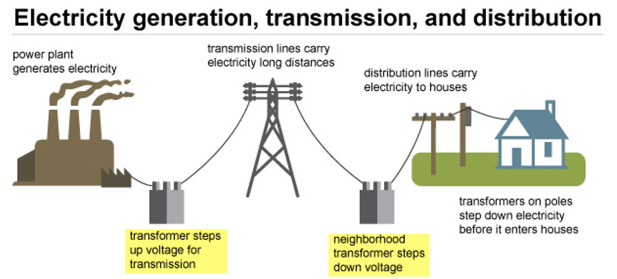
Transmitting electricity long distances is less expensive and more efficient at higher voltages. When the electricity arrives at your home or business the voltage is stepped down (decreased) through a transformer to a lower voltage. At the power plant transformers increase (step up) the voltage and then when needed for home or office use the voltage is reduced (step down) to a safer level.
A transformer receives electric power in its primary windings and transforms it into electric power in the secondary windings of the same frequency. The voltage can be increased or decreased but will have a proportional decrease or increase in current.
Physical Construction of Transformers
In the three-phase transformer the windings are tightly housed in some form of sheet-metal container. A layer of insulation will separate the windings from each other and from the housing. The coils sit between a layer of insulation to keep them separated while still allowing magnetic induction to occur.
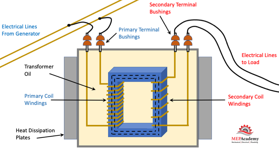
The housing will be filled with oil or a synthetic fluid that serves two purposes, one to keep the transformer cool, and the other as an additional insulating material. You may see transformers with corrugated sides to provide additional surface area for cooling. The heat is transferred from the core and windings to the oil and then to the shell of the transformer where it radiates out to the atmosphere.
Checkout these Electrical Transformers here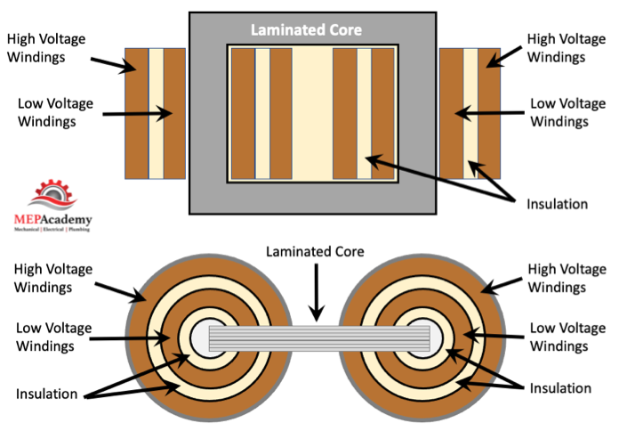
The electrical leads penetrate the transformer housing with protective bushings of porcelain or oil-filled and capacitor types for high voltage applications.
How a Transformer Works
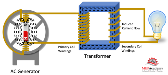
The transformer has two circuits, a primary coil winding and a secondary coil winding linked by a common magnetic flux. The primary and secondary windings are separate coils but are magnetically linked.
When current flows through a conductor like a wire, a magnetic field is created around the wire. When a bunch of that wire is wound closely together like in a transformer then the magnetic field becomes much stronger, allowing for the transfer of power by magnetic induction from the primary coil to the secondary coil. This magnetic field induces a current to flow in the secondary side of the transformer if the circuit is closed. The alternating current will push and pull on the electrons causing the current to flow.
When the magnetic flux lines from the expanding and contracting magnetic field of the primary windings overlap the secondary windings, a voltage will be induced in that coil.
With the use of magnetic induction, we can transfer energy from one set of coils in a transformer to another set of coils. The alternating current produces this magnetic flux. The electricity flows from the primary coil which receives the AC power from the generator to the secondary coil that will serve the load where the electricity will be used. This transfer of electricity occurs without a change in frequency.
For current to flow in the secondary windings the circuit must be closed and connected to a load, like a motor.
The magnetic core of the transformer becomes magnetized from the alternating current that is created from the incoming alternating voltage hitting the primary windings.
Transformers can only work with AC or alternating current electricity, and not with DC or direct current electricity.
Step-Up and Step-Down Transformers
We mentioned that the voltage at the power plant is stepped up to increase the voltage for greater efficiency when transferring the power over long distances, this is because higher voltages require less current or amps, which means smaller wires for transmission, which equals less cost for transmission.
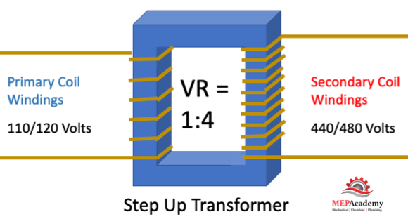
The step-up transformer Increases the voltage while decreasing the current. This is done by having more turns of the coil windings on the secondary side compared to the primary as indicated by the turn ratio.
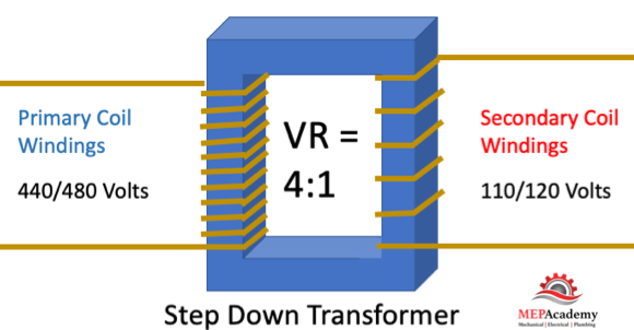
The step-down transformer decreases the voltage and increases the current. This is done by having less turns of the coil windings on the secondary side compared to the primary.
Checkout these Electrical Transformers hereTurn Ratio of Transformer Coils
Each coil of the transformer contains a certain number of turns of wire that wrap around within the transformer. The turn ratio compares the amount of turns of wire on the primary coil windings to the secondary side. This turn ratio can be expressed with an equation.
Turn ratio = Np/Ns
Np = number of turns on the primary coil windings
Ns = number of turns on the secondary coil windings
Voltage Ratio
The voltage of the coil windings in a transformer is directly proportional to the number of turns on the coil windings.
Vp/Vs = Np/Ns
- Vp = voltage on primary coil
- Vs = voltage on secondary coil
- Np = number of turns on the primary coil
- Ns = number of turns on the secondary coil
The voltage ratio (VR) is expressed as the relationship of the primary voltage to secondary voltage.
A voltage ratio of 1:4 means that for each volt on the primary, there will be 4 volts on the secondary. This would be a step-up transformer as the voltage on the secondary side has increased. (See image above)
A voltage ratio of 4:1 means that for every 4 volts on the primary, there will be 1 volt on the secondary. This would be a step-down transformer as the voltage on the secondary side has decreased. (See image above)
For example, if we have a transformer that reduces voltage from 120 volts in the primary to 12 volts in the secondary, and the primary windings has 300 turns and the secondary has 30 turns, the voltage and turn ratio would be as follows,
VR = Vp/Vs = 120/12 = 10:1
TR = Np/Ns = 300/30 = 10:1
Three Phase Transformers
Using a three-phase transformer is like a single-phase transformer except that we have three single-phase windings instead of one. With these three windings we can connect them together in a wye or delta configuration, or a combination of the two.
The 3-phase power is the most common way that power is produced. Large scale power plants generate voltages of 13 kV or higher. This electrical power gets sent over the transmission wires at much higher voltages of 110, 132, 275, 400 and 750 kV. These voltages are increased by three phase step-up transformers for higher efficiency transmission. The transmission voltages then arrive at the load centers where they are reduced to distribution voltages of 6,600, 4,600 and 2,300 volts. This distribution voltage than gets reduced or stepped down to utilization voltages that the consumer uses at voltages of 440, 220 or 110 volts. Transformers are highly efficient at full load with efficiencies running 95% or greater.
Delta Connection
All three phases are connected in series to form a closed loop using a delta connection.
Wye Connection
The common end of each of the three phases are connected at a neutral terminal, while their other ends are connected to three-phase lines in a wye connection.
