


Basic HVAC Controls. Most modern residential and commercial building are built with some form of an HVAC systems to control the interior environment. These HVAC systems are used to control temperature, pressure, humidity, flow, and air quality. In this video we’ll show you how these HVAC systems use various controls to respond to the needs of the environments that they seek to control.
Scroll to the bottom for a FREE YouTube Video of this Presentation.
The importance of the HVAC system is usually appreciated on the hottest or coldest days of the year when you really notice the difference between outdoors and the controlled indoor environment. The HVAC systems are designed to be able to meet the peak demand for each of the seasons, summer highs and winter lows. Most of the year the HVAC system will run at partial load, where the full capacity of the system is not used.
The demand on the HVAC system changes throughout the year and daily. HVAC systems are sized based on Heating and Cooling loads, often performed by load calculation software. Below are some of the most common load calculation and energy modeling software.

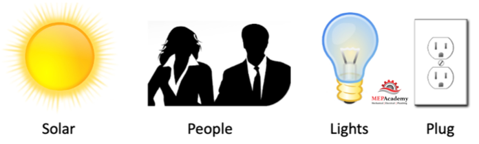
The load calculations will take into consideration the solar load on the structure, the quantity of people in each space, heat from lights, and the plug load, which is all the equipment and appliances that use power and generate heat within the building.
The HVAC control system will need to respond to these changes to maintain the environmental conditions such as Temperature, Pressure, Humidity, and Air Quality. HVAC systems can be used to control the environment for people, food, cleanroom processes for computer chip manufactures or pharmaceutical drugs, animals, IT equipment in data centers, and hospital procedures. The scope of application is endless, but we’ll stick to the control of the environment for humans.
HVAC systems use some form of controls from the very basic to the very sophisticated BMS, Building Management Systems that can monitor and control everything from the HVAC system, lighting, fire systems, and security systems.
We can control a simple single standalone piece of equipment like a home air conditioner or hundreds of pieces of HVAC equipment all networked together and controlled from a frontend computer in the facility managers office or remotely.
On/Off Control
The most basic form of control is to turn on and off a piece of equipment with an on/off switch. You have two options, either the equipment can be on or off. This can be done with a simple light switch as an example.
Carbon Monoxide Garage Exhaust System
We’ll use an underground parking garage for our example, as everyone has been in one of these. With a simple on/off switch we can turn the garage exhaust fan on when the garage is occupied and shut it off when all the cars leave. Not very efficient, and against code in most jurisdictions.
We can automate this by adding a carbon monoxide controller and sensor to activate the fan when the total CO level reaches the setpoint of the controller.
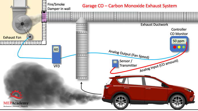
The CO Sensor will send an analog input signal to the carbon monoxide controller indicating the current CO concentration, and when the set point of the controller is reached, meaning that the level of CO in the garage has reached a level that requires the exhaust fan to be turned on, the controller will send a binary signal to the fan to start.
This input device or CO transmitter senses if there is a buildup of car exhaust. We can now add more controls for better energy efficiency, such as a VFD.
Now the CO sensor sends the current concentration of CO in the garage to the controller. The controller will compare that to the setpoint, if the input signal CO levels is greater than the controller setpoint, the controller will send an analog output signal to the VFD, variable speed drive to speed up the fan. The output signal is considered an analog signal because it can vary. The speed of the fan will be based on the level of CO in the garage. Instead of on/Off, we can provide the proper fan speed to match the exact conditions in the garage, helping to avoid using too much energy.
Additional Binary Output Devices
We can still add a few more binary output devices to bring attention to a dangerous situation. By adding two more output devices, a strobe light, and a horn we can notify garage occupants that the levels of carbon monoxide have reached a dangerous level. The carbon monoxide controller will have a setting that sends a binary signal to the horn and emergency strobe light to turn on when the CO exceeds a hazardous level.
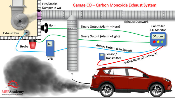
You can see that using a controller allows you to add input and output points to any system. The garage exhaust fan can be setup to run at low and high speed or if acceptable to the local code be run using a VFD.
Controllers, Sensors and Controlled Devices
Now we’ll explain the function of the controller, sensors, and controlled devices.
There are four basic elements of a control system: controller, sensor, the controlled device, and the source of energy, such as electrical or pneumatic.
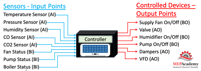
These special sensors monitor and measure variables like, temperature, humidity, pressure, flow, and air quality and provide controllers with the status of the space. These parameters can’t be done with a simple on/off setting. The analog input and output devices send or receive a variable current, voltage or resistance between a minimum and maximum value. This allows for an accurate measurement.
There are different types of signals produced by sensors, which include: Electronic, Pneumatic or Electric Sensors. Pneumatic systems are prone to leaks and are being changed out whenever possible as they are less energy efficient than DDC.
Pneumatic sensors put out a 3 psig to 15 psig pressurized air signal, electronic sensors can be resistance, voltage, or current based sensors, with a voltage signal range of 0 to 10vdc, a current signal range of 4 to 20 mA (milliamps)
Controller
The controller is the brain that makes the decisions based on settings entered by the controls company according to the specifications and sequence of operation. The controller receives inputs from sensors and compares that to the controllers setpoint and then provides a response to output devices. The inputs inform the controller of the existing environmental condition, and then the controller directs the output devices to change the environment to meet the setpoint.
Much like your brain is the controller taking input from your senses, like taste, smell, hearing, vision, and sense of touch. The brain will take the input from your senses and direct an output signal on what the body should do with that information, such as move hand away from hot stove, or spit out a hot pepper, or a visual input of a man with gun, will provide the response or output to run away fast.
There are all kinds of input and output devices for controlling the environment. Each device is meant to serve a particular purpose.
Binary and Analog inputs and Outputs
The difference between a binary and analog input or output device is the number of positions or steps you can have. A binary input or output device has two options, such as either on/off or start/stop, while an analog device can vary, such as in reading various temperatures and pressures, or in modulating a valve or damper position to increase flow in varying amounts, not just full open or full close.
Analog is used when the environmental element being measured has more than two options. Binary provides for two states, either on/off, low/high, start/stop, etc.
Inputs provide the controller with the information it needs to make a decision, while the outputs are where the controller sends its messages to make adjustments as required to meet the settings of the controller.
A binary input to the controller could be the fan status, whether it’s on or off, while the binary output to the fan from the controller could instruct the fan to start or stop. Each of these inputs and outputs have two options, on/off or start/stop.
An analog input to the controller could be the current speed of the fan when using a VFD, while the analog output could be used to change the speed of the fan using the VFD. Using an analog input or output allows for a range of fan speeds to be used.
Universal inputs allow for either a binary or analog input.
Now we’ll step back to explain a couple simpler devices.
Split System HVAC Unit
Using an on/off switch for your home heater or air conditioner would not be very effective because as we now know there are sensors that can measure the indoor temperature and turn on and off the HVAC unit as required. The typical home thermostat acts as the controller and temperature sensor all in one. You set the desired temperature and the thermostat will try to maintain that setpoint.
To control these environments, you need to monitor or sense the existing condition and compare it to the desired setpoint you’re trying to achieve for the space.
To automate this, we could add a simple bimetal thermostat that would sense the air temperature surrounding the stat or temperature sensor and feed that information to the HVAC equipment. When it got warm in the room the bimetal would expand and make contact in the electrical circuit, causing the air conditioner to turn on. When the air has cooled down it would cause the bimetal in the thermostat to contract and pull away from the electrical contacts, thereby turning off the air conditioner. Now at least you have the HVAC system automated according to temperature.
Scheduling – Time Clock Function
Adding a time clock to the thermostat or BAS will allow additional control based on day of the week or time of day. For example, you could have the thermostat turn on the air conditioner an hour before you get home from work so that the home is already cool when you arrive. A simple timeclock allows the HVAC system to have its own schedule based on time, while the thermostat will be based on temperature. So, with a simple thermostat we can control temperature and time.
With the increase in mobile apps, most of this can be done on your phone, but you’ll still need the hardware component to communicate with your AC unit.
Scheduling is important in commercial buildings because you don’t want the occupants to arrive in the morning on a very cold day to find their offices freezing cold. Another reason is that you want to make sure that the HVAC system can’t run on weekends or during the night when the building is unoccupied as this would be a big waste of energy and money.
With building automation software and their control logic the schedule and the temperature and be optimized beyond just starting an hour before the occupant’s arrival. The automation software will look to optimize the starting and stopping of the HVAC system to provide for energy savings. So, the control program will check with other input devices such as an outside air temperature sensor and zone temperature sensors to determine when to bring on the heating or cooling to meet the design temperature before the occupants arrive.
This will help the controls program calculate how long it might take to heat up the building before the occupants arrive. The colder the outside air the longer it will take to warm up the building, so the earlier the HVAC system heating mode will be turned on.
VAV Box Control
A VAV box is commonly found in medium to large commercial buildings, so this will help explain the basic control sequence for this design. You can see that the VAV Box Controller (#1) is mounted on the VAV box and receives an analog input from the room temperature sensor (#2), meaning it can provide a wide range of temperature readings, the Discharge Air Temperature sensor (#3) is another analog input device, and Airflow Sensor (#4).
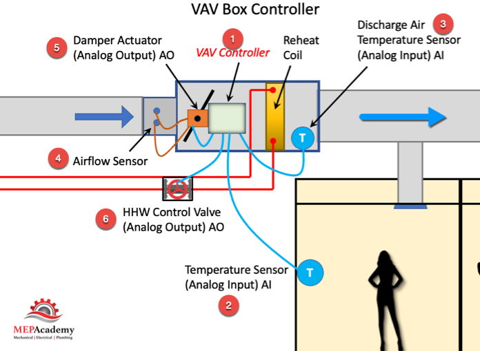
In heating mode, the VAV box controller receives input from the room’s temperature sensor that it’s too cold in the space, the controller then sends a signal to the Damper Actuator (#5) which is an analog output device, to close the damper to minimum position and start to modulate the Heating Hot Water control valve (#6) open, another analog output device.
The controller being the brains, receives input information on which to compare against the setpoint, and then sends an output command to various components to achieve the desired environmental conditions set for this space.
In heating mode, the VAV box damper will be at the minimum open position to avoid wasting energy, as the air arriving at the VAV box has been cooled down at the Air Handler to around 55°F (13°C). We will build on this system by introducing the VAV system and additional control points.
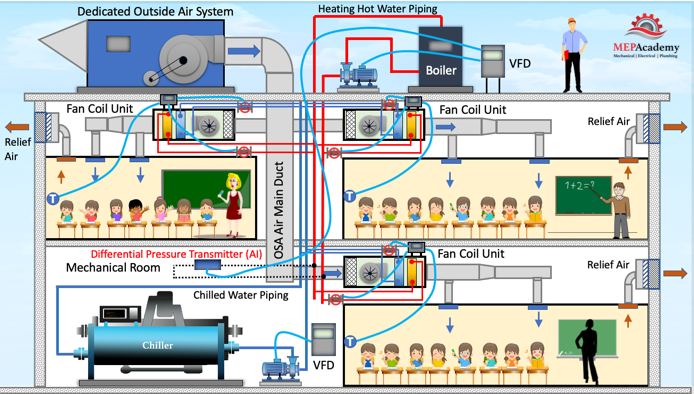
VAV Air Handler System Control
In a VAV system we can add another component of control and that is fan speed. Fan’s use a lot of energy and so being able to reduce their speed will save money. See our video on fan laws to understand the savings potential, and our video on VAV systems which are commonly used in larger commercial buildings.
Fan speed is accomplished by adding a static pressure sensor in the main supply air ductwork. The static pressure sensor is an analog input device which measures the static pressure in the duct. As VAV zone dampers reduce their need for air, they close their dampers causing the pressure in the main supply air duct to increase which is sensed by the static pressure sensor.
The controller will receive the input signal from the pressure sensor that the pressure has increased, and then send a message to the fan to slow down by use of a VFD, variable speed drive. The controller compares the static pressure in the main supply duct to the setpoint and then modulates the supply fan VFD to maintain that static pressure setpoint. As the demand for cooling decreases more, the static pressure setpoint can be reset downward to save additional energy. To learn more about variable speed drives see our Video on VFD’s.
Fan Coil System Control
A similar device in a water-based system would be a differential pressure controller combined with two-way valves on the coils. In a heating hot water or chilled water system, as the modulating 2-way control valves at each coil begin to close, the increased pressure is sensed by the differential pressure controller, an analog input device. This sends a signal to adjust the pump speed using a VFD to reduce the frequency or hertz delivered to the motor on the pump, thereby reducing the flow of water. VFD’s are used to control cooling towers, chillers, pumps, and fans.
All these points can be monitored by the BAS, building automation system for a more optimized and energy efficient system.
Flow Control Valve
Using a thermostat with a control valve connected to a fan coil or radiator we can control the flow of heating hot water or chilled water, either of two ways. First, the 2-way flow control valve can be either a two-position valve, that is either open or closed (binary), or modulating (analog). Using a two position control valve, when there is a demand for cooling or heating, the control valve opens all the way and you get full water flow whether you need it or not.
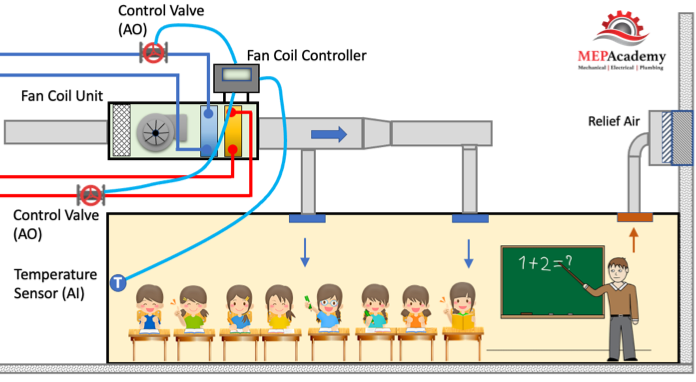
The second method would have a modulating or proportional control valve accept a varying analog signal, like 4 to 20 milliamps. Instead of two positions, full open or full closed, the valve will have various percentages of open. The analog input temperature sensor sends a signal to the fan coil controller indicating the current temperature of the space. The controller compares the current temperature in the space to the desired set point. The greater the distance from the setpoint, the greater will be the response to open the valve.
The controller accepts the input temperature from the sensor, compares it to the set point in its control logic, and then sends an analog output signal to the device being controlled. The controlled device then responds by trying to change the controlled environmental element, in this case it’s the temperature by opening the 2-way control valve an increasing the flow of hot or cold water through the coil.
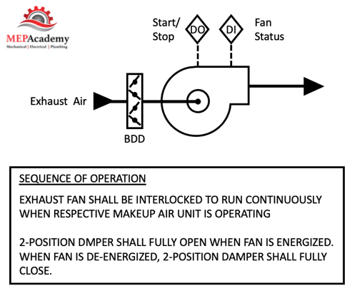
Sequence of Operation
In the commercial controls industry, you’ll hear the term sequence of operation. This is the defined method or sequence upon which the controls are to respond as defined by the mechanical or controls engineer. It defines how the controller along with the input and output devices will achieve control of the environment or space, whether that is a room occupied by humans, animals, or equipment, whether it’s an ice box or central plant. The sequence of operation explains how the system is designed to operate.
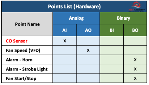
Points List
The points list is a quick reference chart that list all the input and output points required to meet the sequence of operation strategy. You’ll find these on commercial construction control drawings. Here is the one for our simple Garage Exhaust CO Monitoring Controls System.
Control Drawings
The control drawings provide a schematic diagram of where and how the individual control devices are connected overall. See our video on the 6 Steps for Designing a HVAC DDC Controls System
