


 Overrides: Risks, Failures, and Best Practices")


Building automation input sensors.
In this article we’ll cover some of the most commonly used building automation input sensors and where there located. Building control sensors are located throughout a building in strategic positions to monitor and control various aspects of the building’s systems.
If you prefer to watch the video of this presentation than scroll to the bottom click on this link. Building Automation Input Sensors
Here are some commonly used building automation control sensors and why they’re used.
Current Sensor
A Current sensors, also known as current transducers, are used to measure the electrical current flowing through a conductor or piece of equipment. They play a key role in tracking energy usage of equipment by monitoring the current draw.
The current sensor is typically installed around the conductor carrying the electrical current of the equipment being monitored. The sensor may be a split-core design, allowing it to be easily clamped around an existing wire without interrupting the electrical circuit.
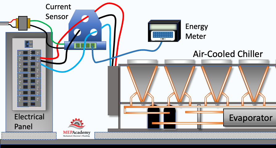
The output signal of the current sensor is typically an analog voltage or current that is proportional to the measured current. This signal can be fed into data acquisition systems, energy meters, or control systems for further processing and analysis.
By continuously monitoring the current draw using the current sensor, the energy usage of the equipment can be calculated. The output signal from the current sensor can be processed and integrated over time to track the energy usage of the equipment. This information can be used for energy monitoring, load profiling, energy management, or billing purposes.
Checkout these Building Automation Books hereDew Point Temperature Sensor
A dew point temperature sensor is used to measure the dew point temperature, which is the temperature at which air becomes saturated and condensation begins to form. There are some that calculate the dewpoint by reading the temperature and humidity and having an onboard program calculate the dewpoint temperature.
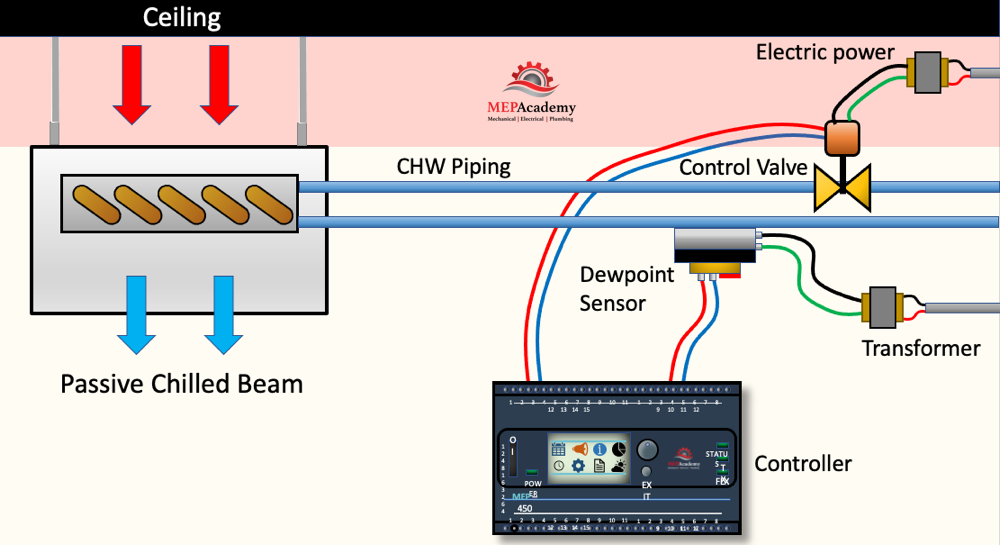
A dewpoint temperature sensor is required on a chilled water radiant panel, like this chilled beam here. This dewpoint sensor is mounted on the pipe and sends the information to the controller. If the dewpoint temperature hits the setpoint, an output signal is sent to the control valve to close, preventing anymore chilled water from circulating through the chilled beam until the proper conditions are met that prevent condensation from occurring, as chilled beams have no condensate drains.
Carbon Monoxide Sensor
Carbon monoxide (CO) sensors are commonly used in conjunction with garage exhaust systems to monitor the concentration of CO in the air and ensure the safety of occupants.
Garage exhaust systems are designed to remove exhaust gases, including CO, from the garage space. They typically include ventilation fans or ductwork connected to the outside. The CO sensor can increase the fan speed in conjunction with a VFD when certain concentrations of carbon monoxide are reached. The activation of the exhaust system helps to reduce CO levels, providing a safer environment for occupants.
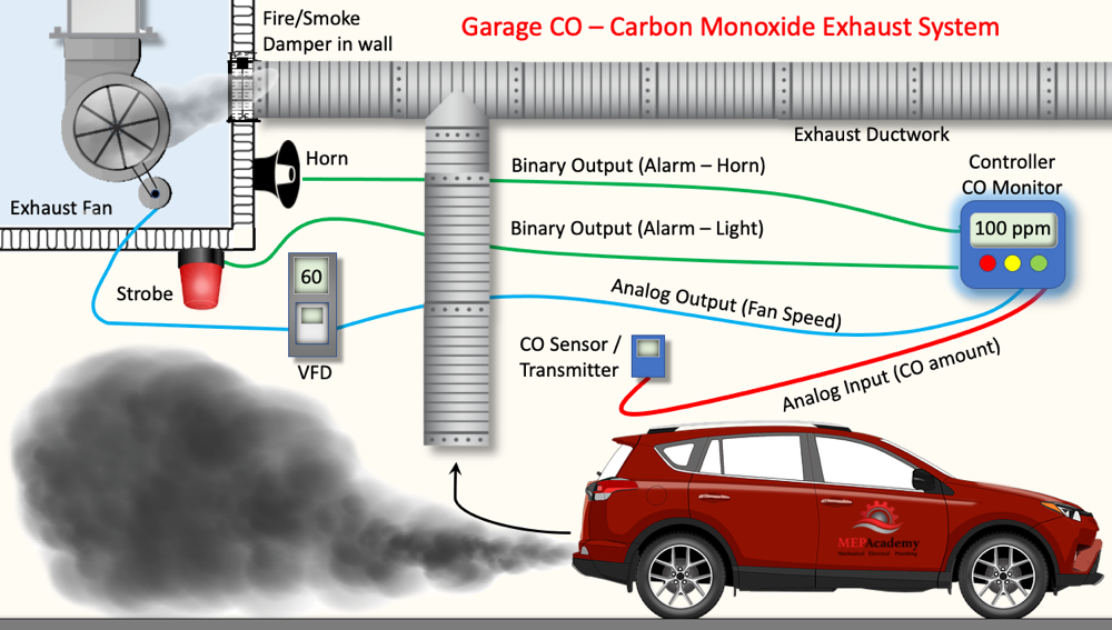
When the CO concentration exceeds the threshold, the sensor can provide an audible or visual alarm to alert occupants of the hazardous conditions.
Differential Pressure Transmitter for Dirty Filters
Differential pressure is used to indicate when filters have become dirty. When the filters are clean there is less pressure drop across them. As dirt becomes trapped on the filter media the pressure drop across the filter increases which increases the differential pressure.
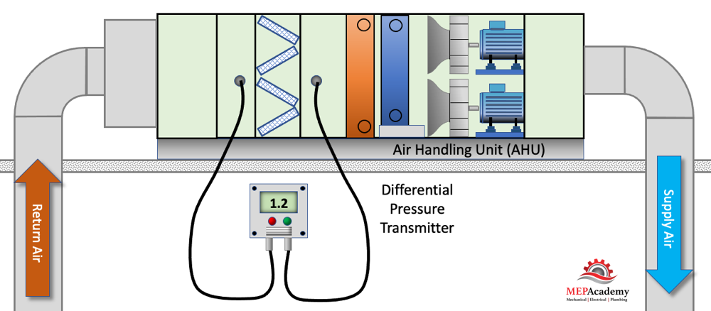
By putting a differential pressure transmitter an alert can be sent to the facility personnel to change the filters. Increased pressure drop across the filter causes an increase in fan energy and utility cost.
CO2 Sensors
Carbon dioxide (CO2) sensors are used to monitor indoor air quality and ensure adequate ventilation. They are often placed in areas where people gather, such as conference rooms, classrooms, and auditoriums. CO2 sensors, when integrated with economizers, play a vital role in controlling ventilation air to a room based on the levels of carbon dioxide (CO2) present in the indoor environment.
The CO2 sensor continuously measures the concentration of carbon dioxide in the air.
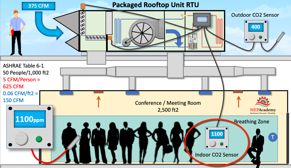
Based on building codes and standards, such as ASHRAE standard 62.1, there are recommended or required ventilation rates for occupied spaces. These rates are designed to maintain healthy indoor air quality. CO2 sensors help determine if the current ventilation rate is adequate or if adjustments are necessary.
The CO2 sensor provides a control signal based on the measured CO2 concentration. As CO2 levels rise due to occupancy or other factors, the sensor sends a signal to the building automation system (BAS) or the economizer control system.
When the CO2 concentration surpasses a pre-set threshold (often referred to as the setpoint), the economizer control system increases the outdoor air intake. This adjustment brings in more fresh air from the outside to dilute the CO2 and maintain acceptable indoor air quality.
The setpoint for the CO2 concentration can be adjusted based on the specific requirements of the space and occupant density.
Checkout these Building Automation Books hereDifferential Pressure Sensor
Differential pressure sensors, in combination with variable frequency drives (VFDs), can be used to control the speed of pumps in a system. Here’s a general explanation of how this control mechanism works:
Differential pressure sensors are installed in the system to measure the pressure difference between two points, typically just before the most remote coil in the system. The sensor measures the difference in pressure across a flow element, such as an orifice plate or a flow sensor.
The differential pressure sensor provides a feedback signal to the control system, indicating the actual pressure differential in the system. This feedback is used to determine the flow rate and the speed of the pump using a variable speed drive (VFD). See our other video on “How VFD’s work”
A desired or target differential pressure setpoint is established based on the system requirements and design parameters. The control logic compares the actual differential pressure (feedback signal) with the setpoint.
Based on the comparison between the actual differential pressure and the setpoint, the control logic determines whether the pump speed needs to be adjusted. The control logic sends a control signal to the VFD to modulate the speed of the pump motor.
The VFD receives the control signal and adjusts the frequency and voltage supplied to the pump motor accordingly. By reducing or increasing the frequency, the VFD changes the speed at which the pump motor operates.
As the pump speed changes, the flow rate through the system is adjusted. The control system continuously monitors the differential pressure and adjusts the pump speed through the VFD as necessary to maintain the desired setpoint and optimize system performance.
By utilizing the feedback from differential pressure sensors and adjusting the pump speed through VFD control, the system can effectively maintain a desired pressure differential, regulate flow rates, and achieve energy savings by matching the pump speed to the system’s actual requirements.
Occupancy or Motion Sensors
These sensors detect the presence or absence of people in a room or area. They are commonly placed in spaces such as offices, meeting rooms, restrooms, and hallways to control lighting, HVAC systems, and security systems based on occupancy.
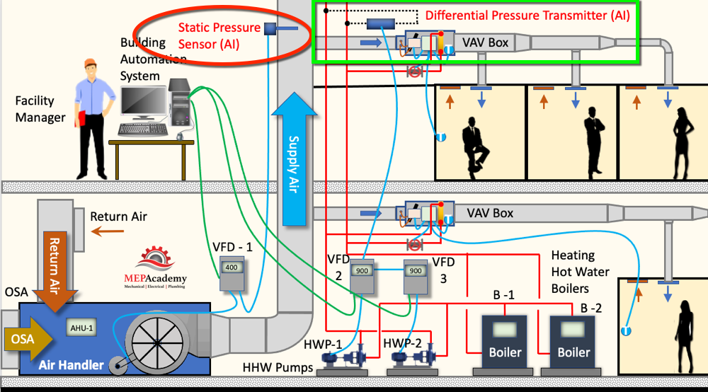
Static Pressure Sensor
A static pressure sensor is commonly used to control fan speed and maintain a desired static pressure within a duct. (See image above for example)
The static pressure sensor is typically installed at a strategic location or approximately two-thirds of the way down the main ductwork.
The static pressure sensor contains a pressure-sensing element, such as a diaphragm, that is exposed to the air pressure in the system. As the air flows, the pressure changes, and the diaphragm deflects in response to these pressure variations.
The deflection of the diaphragm generates an electrical signal proportional to the static pressure. This signal is transmitted to the control system for further processing.
The control system is programmed with a desired static pressure setpoint, which represents the target pressure level. The control logic continuously compares the measured static pressure from the sensor with the setpoint.
Based on the comparison between the measured static pressure and the setpoint, the control logic determines whether the fan speed needs adjustment to maintain the desired static pressure. If the measured static pressure deviates from the setpoint, the control logic sends a control signal to the fan motor or a variable frequency drive (VFD) to adjusts the speed of the fan motor.
There is a variation of the fixed static pressure setpoint strategy that uses resetting of the static pressure setpoint based on the feedback of terminal damper positions.
By utilizing a static pressure sensor in conjunction with fan control systems, HVAC systems can maintain the desired static pressure levels or reset levels, optimize airflow, and ensure efficient operation. This control mechanism helps balance air distribution, control temperature differentials, and improve energy efficiency in HVAC applications.
Pressure Monitor
In a hospital operating room, pressure monitors are used to ensure and control the air pressure within the room to maintain specific pressure differentials and prevent the entry of contaminants. Here’s a general overview of how a pressure monitor helps control the pressure in a hospital operating room:
Pressure Monitoring: The pressure monitor is typically installed in the operating room and is connected to pressure sensors strategically placed within the room. These pressure sensors measure the air pressure inside the operating room and provide real-time feedback to the pressure monitor.
Setpoint and Control Logic: The pressure monitor is programmed with a setpoint, which is the desired pressure level for the operating room. The control logic within the pressure monitor continuously compares the measured pressure from the sensors with the setpoint.
Differential Pressure Calculation: The pressure monitor calculates the pressure differential between the operating room and adjacent areas or reference points, such as the corridor or anteroom. This differential pressure is crucial to ensure air flows from clean to less-clean areas, preventing the ingress of contaminants into the operating room.
Control Action: Based on the comparison between the measured pressure and the setpoint, the control logic determines whether the pressure needs adjustment to maintain the desired differential pressure. If the measured pressure deviates from the setpoint, the control logic triggers a control action.
Air Handling System Control: The pressure monitor sends control signals to the air handling system, which may include HVAC systems, fans, and dampers. These control signals adjust the airflow rate, temperature, and damper positions to modify the air supply and exhaust within the operating room.
Pressure Correction: By controlling the airflow rates and adjusting dampers, the air handling system modifies the air pressure within the operating room. The objective is to bring the measured pressure back to the desired setpoint, thereby maintaining the proper pressure differential.
Alarm and Alerts: Pressure monitors often incorporate visual and audible alarms to alert personnel in the event of pressure deviations beyond acceptable limits. This allows for immediate attention and corrective action to maintain the required pressure conditions.
Real-Time Monitoring: Pressure monitors provide continuous real-time monitoring of the pressure in the operating room, ensuring that the pressure differentials are maintained within the specified range throughout surgical procedures.
By utilizing pressure monitors in conjunction with the air handling system, hospital operating rooms can effectively control the air pressure to create a controlled environment that minimizes the risk of contamination and supports a sterile surgical environment.
Humidity Sensor
A humidity sensor, also known as a hygrometer, is a device used to measure and monitor the moisture content or relative humidity in the air. There are different types of humidity sensors, but one common type is the capacitive humidity sensor. Here’s a simplified explanation of how a capacitive humidity sensor works:
Capacitive Principle: The capacitive humidity sensor utilizes the principle that the electrical capacitance of a material changes with the amount of moisture it absorbs. It consists of two conductive plates separated by a moisture-absorbing dielectric material.
Dielectric Absorption: The dielectric material used in the sensor has the ability to absorb water molecules from the surrounding air. When the moisture content in the air increases, water molecules are adsorbed onto the dielectric material, causing it to expand.
Capacitance Change: As the dielectric material expands or contracts due to moisture absorption or release, the distance between the conductive plates changes. This variation in distance alters the capacitance between the plates.
Capacitance Measurement: The sensor measures the capacitance between the plates using an electronic circuit. This circuit applies an electrical charge to the plates and measures the time it takes for the voltage to decay. The rate of decay is influenced by the capacitance, which in turn is influenced by the moisture content.
Conversion to Relative Humidity: The capacitance measurement is converted into a relative humidity (RH) reading using calibration curves or algorithms. These curves or algorithms map the capacitance values to corresponding relative humidity levels, providing an accurate humidity reading.
Output and Integration: The humidity sensor provides an output signal, usually in the form of an analog voltage or a digital signal, which can be interpreted by a microcontroller or other electronic systems. This information can be used to control ventilation, HVAC systems, or trigger alerts based on humidity thresholds.
It’s important to note that humidity sensors require calibration to ensure accurate readings, as factors such as temperature and aging can affect their performance. Additionally, there are other types of humidity sensors, such as resistive, thermal, and dew point sensors, which operate on different principles but serve the same purpose of measuring humidity.
Light Sensors
Light sensors, also known as photocells or light-level sensors, measure the amount of light in a space. They are typically placed near windows or in open areas to automatically adjust the artificial lighting levels based on the available natural light.
Water Flow Sensors
These sensors are installed in plumbing systems to monitor water usage, detect leaks, and prevent water damage. They can be found near water fixtures, in mechanical rooms, or along water supply lines.
Smoke and Fire Sensors
Smoke detectors and fire sensors are crucial for fire safety. They are typically installed in various locations throughout a building, including hallways, common areas, and individual rooms.
Checkout these Building Automation Books here