


Chapter #3 – Plan, Elevation, Section Views and Details
You will need to understand how to read a set of engineered drawings before you can begin any sort of material takeoff or communication with others. This section of the course will explain how to understand and read the various elements of an engineered set of drawings.
Plan Views
The plan view is where all the floor plans are shown including other areas such as the Roof Plan.
Floor Plans
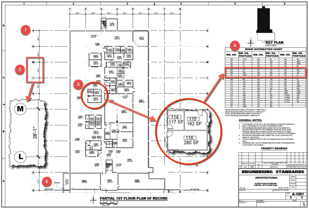
Each floor in the building will have its own drawing, unless the floor is too large to fit onto one drawing then there will be more than one drawing per floor. The floor plan shows all the rooms, doorways, windows, stairways, elevators and whatever the Architect believes is pertinent information for an understanding of the floor plan. The Architects as indicated below as identified the following on this floor plan;
- Column number
- Distance between columns
- Room designation and size of room in square feet (SF)
- Room information chart (Schedule) listing each room number and its corresponding square feet.
- Match line indicates that there is a continuation of this floor plan on another drawing.
Roof Plan
The roof plan is important as this is where some of the mechanical equipment is located. Roof exhausters, cooling towers, pumps, boilers, intake hoods and other HVAC equipment can often be found on the roof.
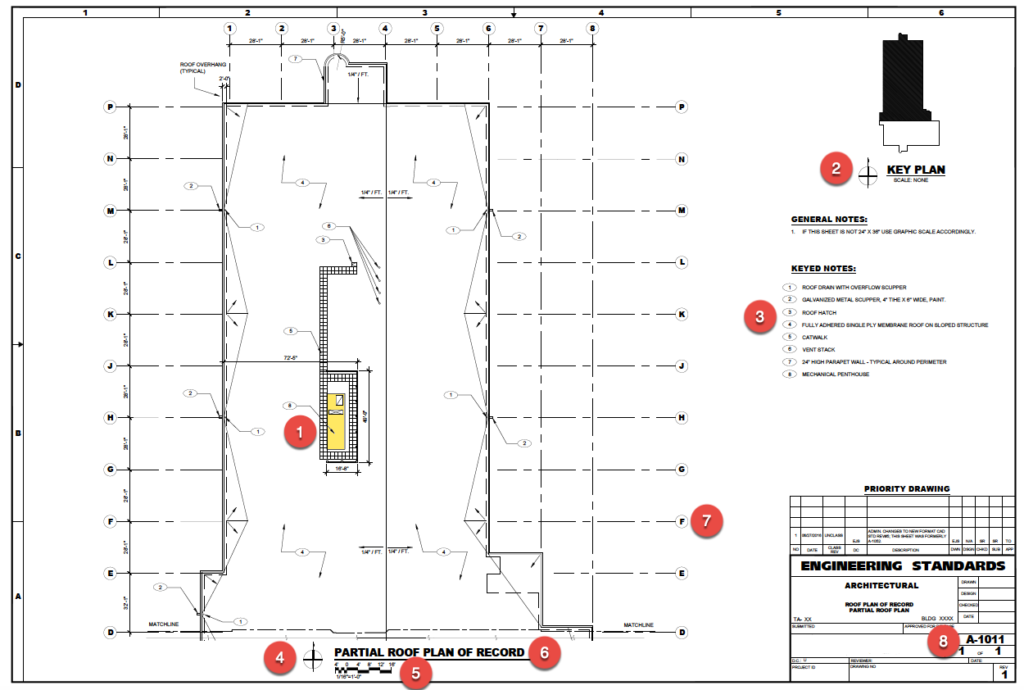
Looking at the roof plan we can see the following on the plans as indicated by the red circles;
- HVAC Equipment
- Key Plan as explained below
- Key notes that help explain what’s on the roof plan.
- The North arrow. This indicates the buildings orientation to the north pole.
- The drawing scale in bar format. This allows for an easy scale verification using any scale.
- The description of the plan view, in this case it’s indicated as being a “Partial” roof plan. This would give you an indication that there is another part of the roof not shown here.
Key Plan
The key plan identifies the area of the building that is being shown on the current drawing. For buildings that are too large to fit on one drawing at the standard scale of 1/8” or 1/4”, than the building floor plan needs to be shown on several drawings with match lines drawn to indicate where the drawing has been demarcated into separate drawing areas.
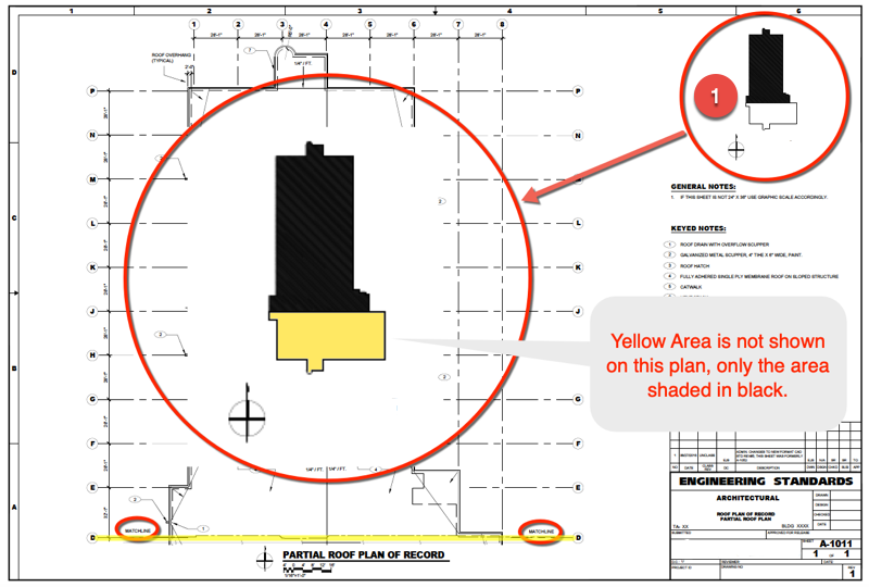
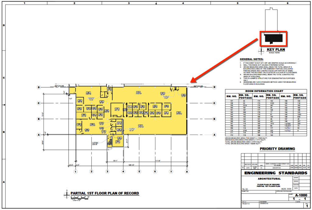
As can be seen from the shape of the shaded black portion of the Key Plan below, and the shape of the floor plan it is referring to, they are the same. So the Key Plan is a mini representation of the shape of the floor plan and the portion of the floor plan that this particular drawing refers to.
Also, the below drawing is the continuation of the floor plan shown above. The Match Lines line up to create a complete floor of the building as indicated by the Key Plan.
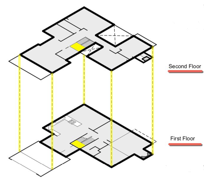
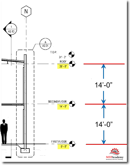
Multiple Floors
You have to visualize how each floor relates to each other. This will help you see the HVAC air ducts an piping risers that travel from the roof to the basement. By using the column lines on one floor, you can find the exact same place on the floor above or below. The yellow highlighted dotted lines align up one floors corner to the nest floor.
Drawing, Section View & Detail References
It would be difficult to provide the details of more intricate construction assemblies on the same drawing of the floor plan. This is where the Detail and Section view references clear up and better show the components and finish of these areas.
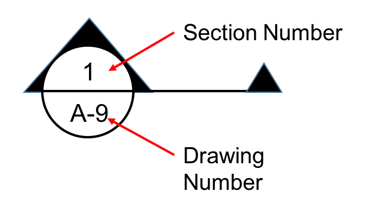
The symbol helps you find the detail or section that is being referenced by the symbol. As shown in the example above the detail or section can be found on drawing “A-9”, Detail or Section #1. The arrows indicate the direction that you would be looking toward. The detail or section view will show you what you would see if you were standing there looking at the building components.
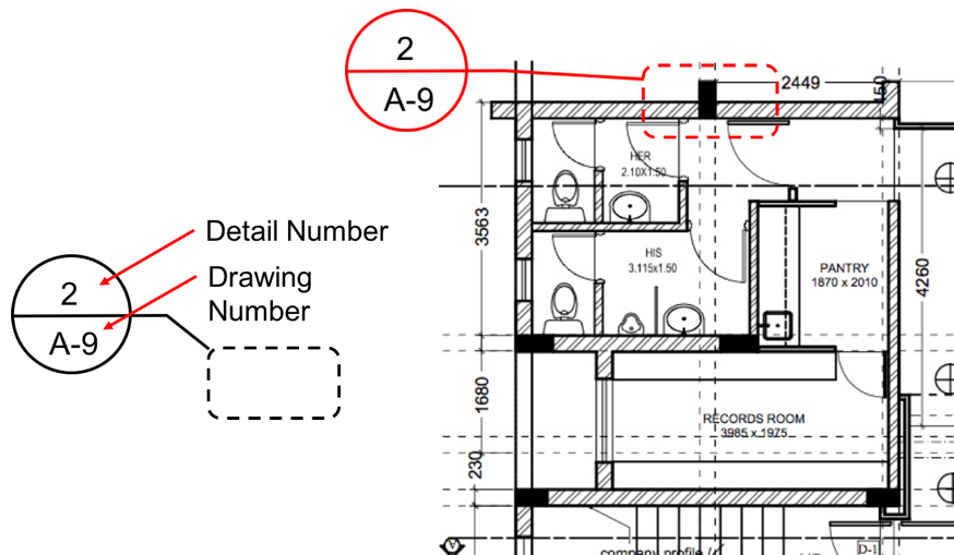
Detail #2 is found on Architectural drawing A-9 as shown by the reference above. The purpose is to show in greater detail the area that is outlined. The dimension shown are in metric.
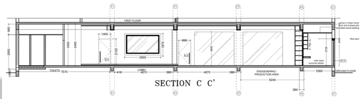
Section View
This Section View comes from a cut of the plan view above. A section view is different than an elevation view. A section view shows a cut of some portion of the building, while an elevation view shows what the building exterior looks like on what of its sides, such as the north side of the building.
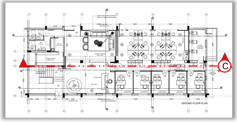
Above is the first floor plan view of a small commercial building with a section cut referenced as “C”. See this section cut below under the Section View.
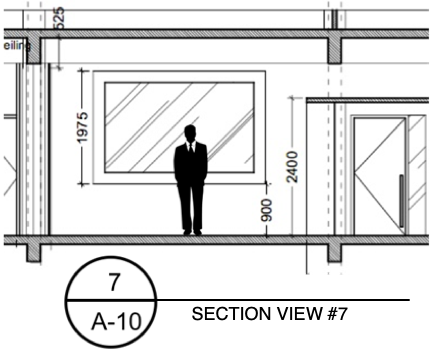
Below is a partial section view of one portion of the interior indicated as Section View #7, as shown on drawing #A-10.
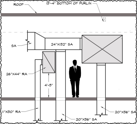
Building Section View
This shows the total section of the building along the cut. These views will help you determine the length of riser ducts that traverse from one level to another.
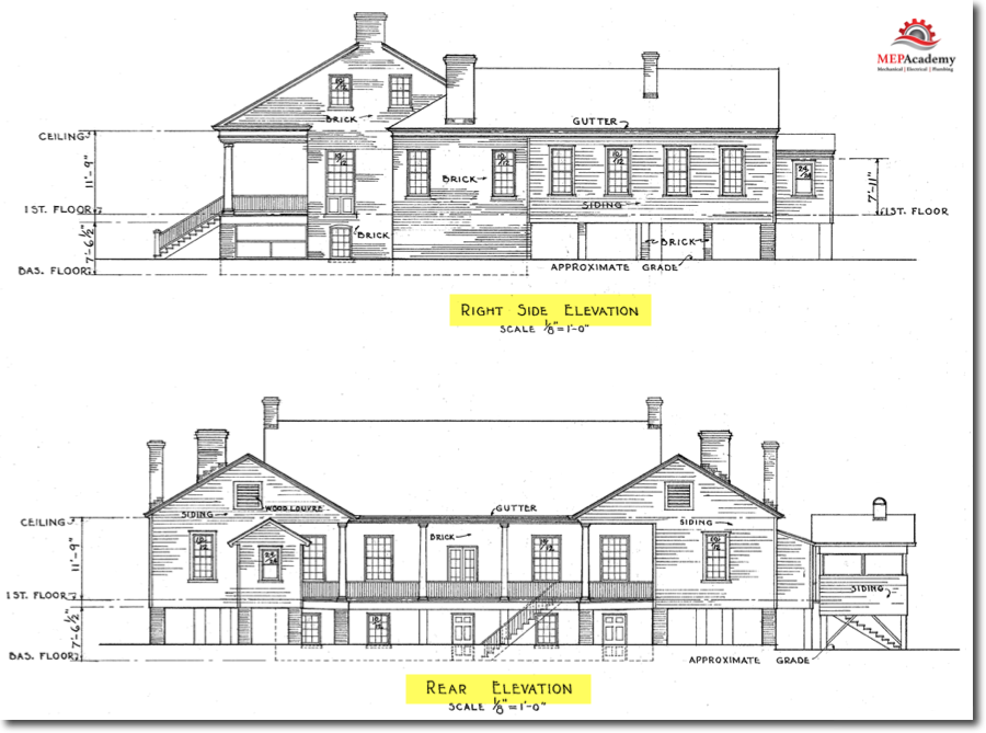
Elevation View
The elevation view shows the outside of the building from every orientation (North, South, East & West).
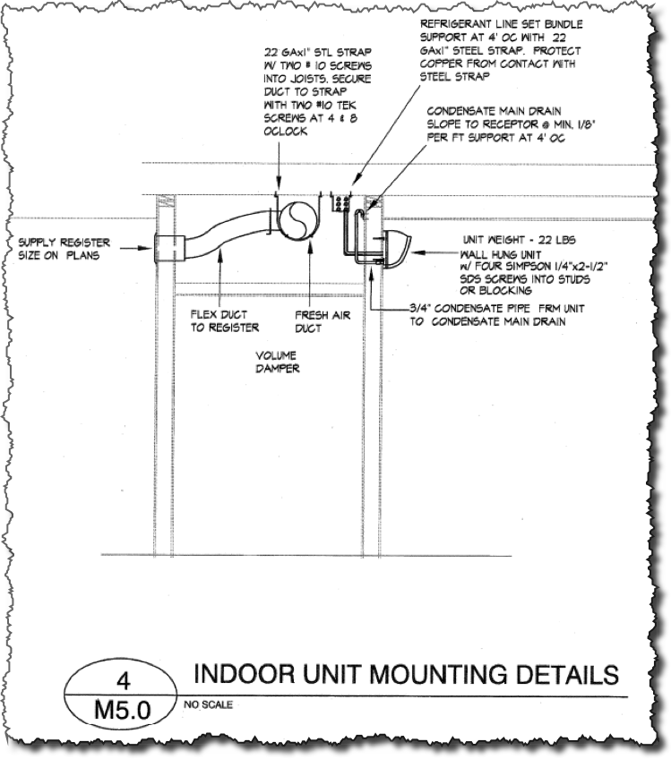
Detail Section View
Detail Views
The detail view provides a look at the building components that make up the area of reference. Details are drawn at a larger scale than the general drawings allowing for a better look at the methods of construction. On Architectural drawings, details could include doors, windows, eaves, while on Mechanical drawings they may show details of hangers, fire dampers, coil connections, equipment trim, and sheet metal duct seams and joints.
Now click the link below for Chapter #4 “HVAC Mechanical Drawings” to get an overview of these drawings.
- Chapter #1 – General Layout of Drawings
- Chapter #2 – Architectural Drawings
- Chapter #3 – Plan, Elevation, Section Views and Details
- Chapter #4 – HVAC Mechanical Drawings
- Chapter #5 – Understanding HVAC Symbols
- Chapter #6 – Drawing Scales (How to Read Scales including Metric Scales)
- Chapter #7 – Sheet Metal Shop Drawings
