


 Overrides: Risks, Failures, and Best Practices")


Chapter #5 – Understanding HVAC Symbols
In order to understand how to read HVAC drawings, you have to understand the road signs (HVAC Symbols). These vary from one engineer to the next, but there are some similarities that will help you figure the differences out. HVAC Symbols work like the road signs you are familiar with; they allow you to discern their meaning by a visual icon or image with very little use of words.
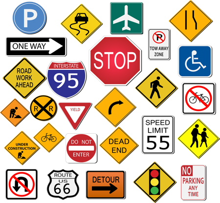
Without HVAC symbols the drawings would be crowded with words and sentences in an attempt to explain what is easily explained with a symbol.
There are symbols for all kinds of equipment, duct specialties, piping components and for all other trades. Symbols are the unspoken language in the construction trade. They convey meaning without words or in conjunction with abbreviations.
There should be a Legend of symbols on the mechanical drawings.
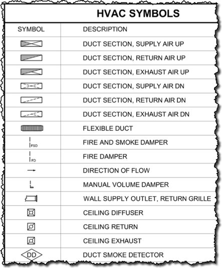
You will find that there is no industry standard and that symbols can vary from one engineer to the next. Often if they are using the same CAD program and the symbols that are standard with the program then you will see similarities.
Don’t be confused by the variations of the same symbol from drawing to drawing. Focus on what the symbol is trying to convey.
Supply, Return & Exhaust Symbols
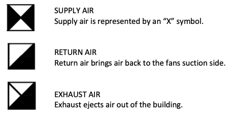
The following are used often throughout the mechanical drawings to indicate which type of air is in the ductwork, or which type of air distribution is being referenced.
The three most common being supply, return and exhaust. An “X” in a square or round shape is indicative of Supply Air, while a single Diagonal line indicates return air.
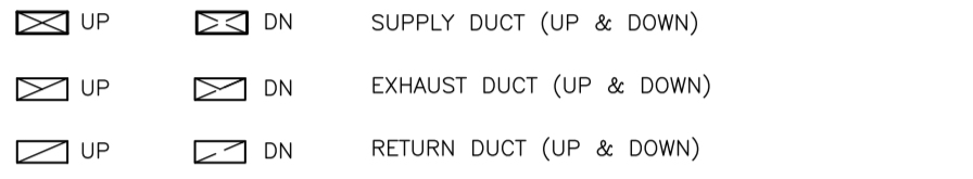
The following symbols indicate the type of air but also that of a riser duct. A riser duct is one that penetrates a floor. When the line is solid, it indicates that the duct is going up, and if the line is dashed, it indicates that the duct is going down.
Duct Risers in Shafts
In multi-story buildings it’s probable that you will have a shaft, which is usually a drywall enclosure that is fire rated to allow utilities, including HVAC ductwork to travel from one floor to another. When the ductwork leaves or enters the shaft it requires a fire damper or a combination fire/smoke damper, in order to prevent fires or smoke from traveling from one floor to another.
When looking at the shaft, you can determine which direction the ductwork is going by whether the lines are solid or dotted. Solid lines indicate that the ductwork is going up, and dashed lines (Hidden Lines) indicate the ductwork is going down.
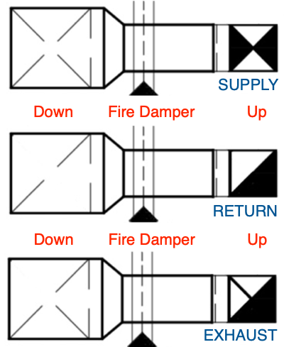
Again, to distinguish which direction the above ducts are going, you only need to remember the rules governing hidden lines. The shafts on the left side show hidden lines (dashed lines) in the riser indicating that the shaft is headed downward, while the shafts on the right show solid lines indicating that these are duct risers going upward.
The above shows what a rectangular duct looks like in each case, while the below represents a round portion of duct that rises up and down. The round duct riser goes down on the left side as indicated by its dashed lines, and the other side goes up as indicated by the solid lines.
Air Distribution
Air distribution devices are used at the end of branch ducts or tapped onto the side of ducts to allow air out of or into the ductwork. Air distribution grilles, registers, diffusers and linears are chosen to allow for the proper dispersion of the air into the room based on acceptable noise criteria, throw distance and throw pattern. The arrows show the direction of the airflow. Supply shows the arrow exiting the air diffuser, while return and exhaust show the arrow pointing into the grille.
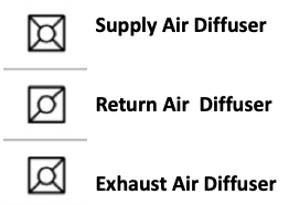
Supply Return Exhaust Grilles
he arrows show the direction of the airflow. Supply shows the arrow exiting the air diffuser, while return and exhaust show the arrow pointing into the grille.
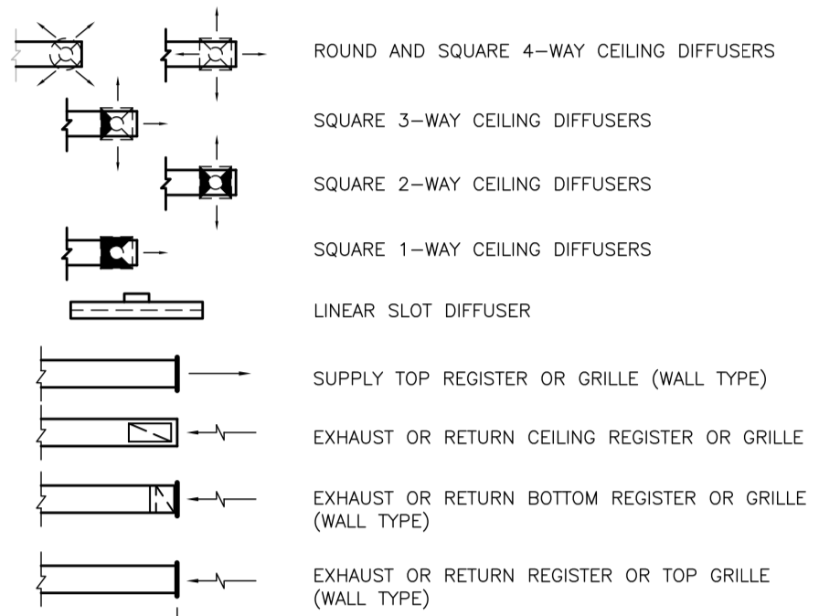
Below is an example of what it might look like on the drawings. Note that different engineers will use different symbols. The below image shows the symbols indicating supply, return and exhaust air distribution devices.
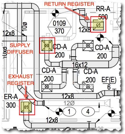
Air distribution grilles, registers and diffusers will often have an acronym that matches an air distribution schedule on the drawing where the equipment is listed, which will define the make and model number for each piece & indicate the CFM.

Ductwork Symbols
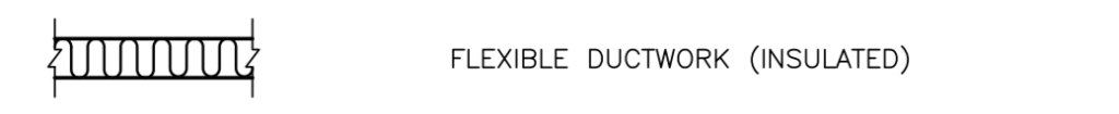
Most ductwork is either shown in single line or double line. There are also various types of ductwork that have their own symbols, such as flexible duct which is often shown as a squiggly line.
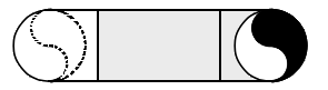
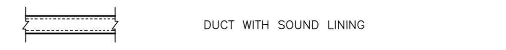
Ductwork can be internally lined for acoustical or thermal reason, that is for the reduction of sound transmission or for the reduction of heat loss or heat gain. This is usually indicated by a dashed line within a solid pair of lines.
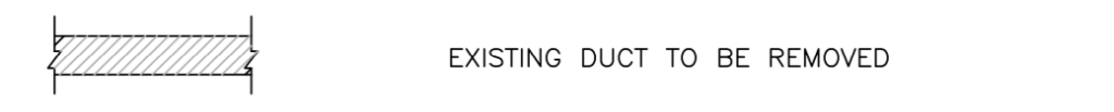
In retrofit projects where the existing ductwork needs to be removed, the symbol that indicates this is usually some form of diagonal hash marks as shown below. Labor must be included in your estimate to remove this ductwork.
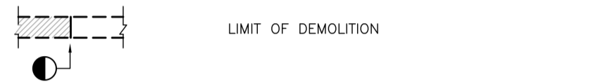
When existing duct is removed as shown above, but not all of the existing ductwork gets removed, there is a symbol that indicates a point at which the existing duct on one side of the line remains, while the duct on the other side of the line gets removed (Demoed)
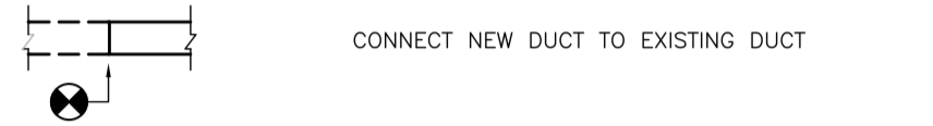
When new ductwork is attached to existing ductwork, engineers will indicate this by using a point of connection symbol. The difference between the new ductwork and the old can also be determined by the type of line used. Lines that are dotted, dashed or thinly drawn are indicative of existing ductwork, while solid lines indicate new.
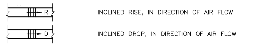
Routing ducts through buildings often require that they rise or drop to get around obstacles. This is indicated with an arrow and with a letter; R (Rise), D (Drop). As a sheet metal estimator you should add a couple of angles (45-degree elbows) or an offset fitting.
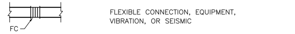
A special type of duct is used to prevent vibration and noise from transmitting down the ductwork from the source. The flexible duct section is used for equipment, but there are also special flex section used for seismic breaks.
Dampers
Fire Dampers
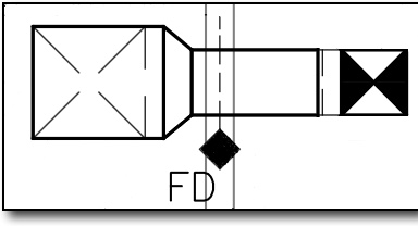
Fire dampers are shown as a dotted or solid line through the duct at the point where it penetrates the fire rated wall, accompanied by a solid diamond, square or other shape, often with the abbreviation FD (Fire Damper) as shown below.
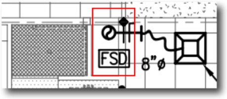
Smoke/Fire Damper
This is a combination of two types of protective dampers, a fire damper, which protects against fires, and a smoke damper, which closes off the air by motorizing a damper closed.
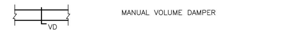
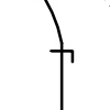
Volume Dampers
The air in an HVAC system requires balancing in order that the air gets to the room in the quantity that the engineer intended. Volume dampers are shown as various straight lines perpendicular to the duct with a small handle.
Automatic Control Dampers
In order to control dampers automatically they need to have some form of actuator that will modulate, open or close to perform some function of the HVAC system.

Miscellaneous Equipment
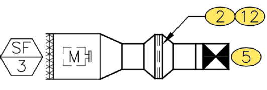
There will be miscellaneous pieces of HVAC equipment that will be inserted into the ductwork. Make sure to review what each symbol represents, as piece of equipment installed in the ductwork often requires transitions or special connections. As shown below this in-line coil which is larger than the ductwork will require two transitions.
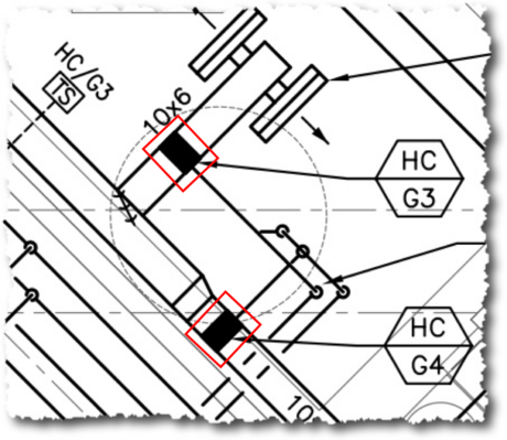
Duct Mounted Coil
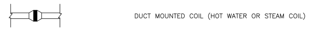
This next symbol represents a piece of equipment, in this case a heating coil as shown by the red outlined box in the image below, but it could be any type of coil.
One of the ways to tell this is a coil is that there are pipes attached to it. Usually you will see two pipes entering the coil, but the engineer has chosen to show only one of the two pipes.
Symbols for a Typical VAV Terminal & Ductwork
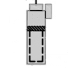
The image below is of a typical VAV (Variable Air Volume) terminal, this is a box connected to the ductwork that varies the volume of air based on the thermostats setting.
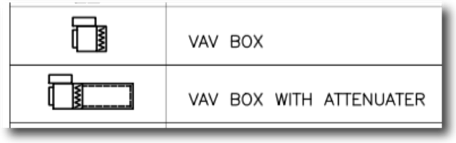
This symbol represents a piece of equipment, in this case a Variable Air Volume terminal box with a lined plenum. The VAV provides a variable amount of air to the diffusers based on the thermostat setting and current room conditions. This could also represent a CAV (Constant Air Volume) terminal box.
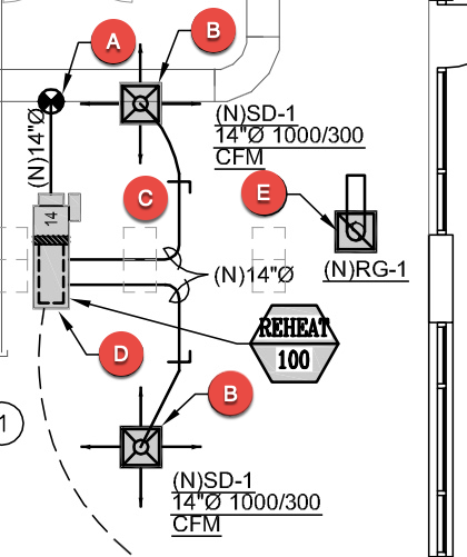
Point of Connection (POC). This indicates where the new ductwork connects to the existing ductwork. Everything from this point forward is new, and everything before it is existing. Often, the new ductwork is shown in dark lines, while the existing is drawn lightly. Also, sometimes the (N) new ductwork includes an (N) before its size, to indicate its new.

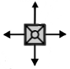
As we learned above the “X” within a box refers to Supply Air, so this here is referencing a Supply Air Diffusers. This also shows that the SA (Supply Air) diffuser blows air in four (4) directions, as indicated by the arrows.
Volume Dampers are used to balance the system so that the correct amount of air (CFM) is provided through the diffuser to the space.
VAV (Variable Air Volume) Terminal. This is a piece of equipment purchased from a supplier, and manufactured by Titus, Metal Aire, Krueger, or similar. This VAV terminal will adjust the volume of air delivered to the space based on the demand of the thermostat.
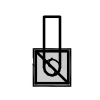
Return Air Grille with a sound boot. This grille provides for air to return from the space back into the attic where it will make its way back to the system by the negative pressure created by the HVAC system. On the Return Air Grilles there is a sound boot, or a piece of lined sheet metal with an elbow to prevent noise from being carried to other spaces.
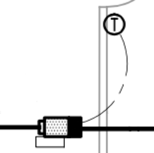
Thermostat
The thermostat controls the temperature setting for the room and controls the HVAC equipment. The symbol for a thermostat is often just a circle with a “T” inside as shown below. The thermostat shown below is controlling a VAV box.
Indication of Demolition
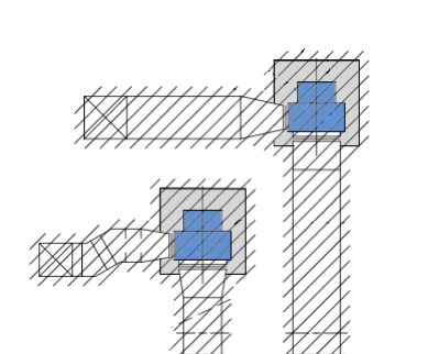
Items that are hashed out as shown in this picture indicate items of a retrofit project that need to be removed. This show two fans and duct that needs to be demoed and removed.
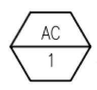
Equipment Tags
These are special symbols that identify the equipment by an acronym and a number. This helps tie together the equipment schedule that list all the equipment with tags that can be located somewhere on the floor plans to show where that piece of equipment resides in or on the outside of the building. This equipment tag (AC-1) represent Air Conditioner #1.
Drawing Notes
Drawings will use numbered tags that refer to a column of numbered notes that might be off to one side of the drawings. Putting the description or notes directly on the drawing next to the item could make the drawing messy and hard to read, it’s easier to put a small number next to the item that the note references.
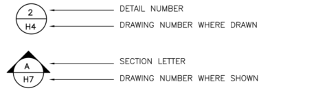
Detail and Section View Symbols
As mentioned previously, these are drawing road signs that point you in the direction of another drawing where a detail or section view is available. These special symbols identify what other drawing that you need to review to understand in more detail the area referenced.
Next is Chapter #6 “Drawing Scales” to see how scales effect your takeoff and how to read scales including metric scales.
- Chapter #1 – General Layout of Drawings
- Chapter #2 – Architectural Drawings
- Chapter #3 – Plan, Elevation, Section Views and Details
- Chapter #4 – HVAC Mechanical Drawings
- Chapter #5 – Understanding HVAC Symbols
- Chapter #6 – Drawing Scales (How to Read Scales including Metric Scales)
- Chapter #7 – Sheet Metal Shop Drawings