


Chapter #4 – HVAC Mechanical Drawings
The mechanical drawings we will be dealing with are specifically related to the HVAC industry. Just like the other trades, the mechanical drawings have a specific purpose to their layout, so as to communicate the requirements of the project.
Typical drawings found in the HVAC Mechanical set of drawings could include some or all of the following;
- Legend
- Abbreviations and symbols
- Equipment Schedule
- General Notes
- Specifications
- Zoning plan
- Demo
- Floor Plan
- Elevations
- Section Views
- Details
- Schematics
- P & ID Drawings
- Control Diagrams
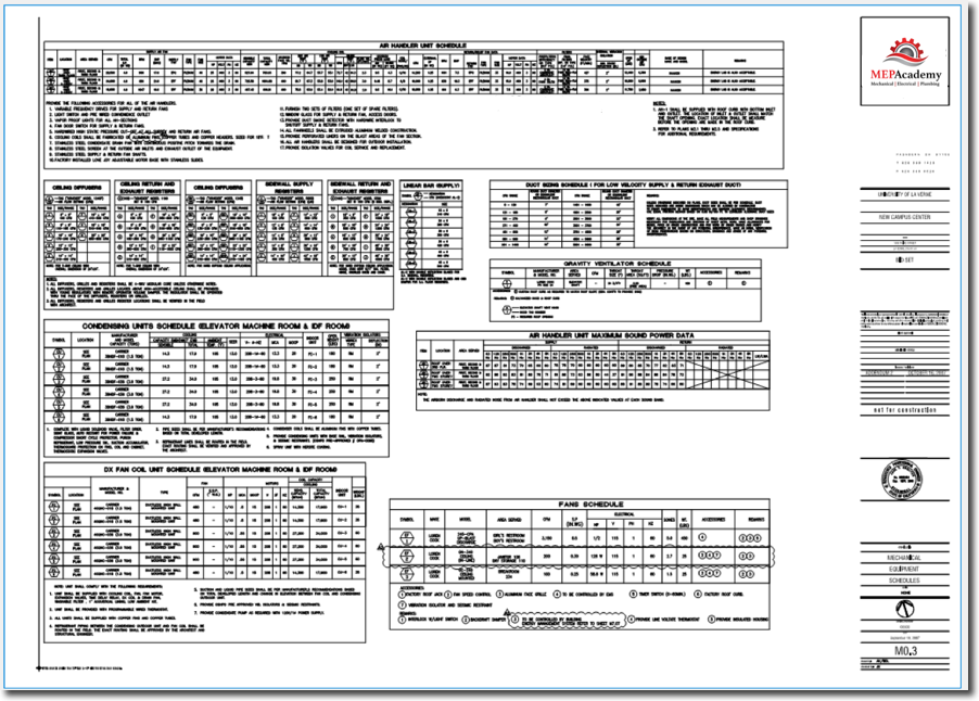
HVAC Mechanical Equipment Schedule
The HVAC equipment is shown on the Mechanical Equipment Schedule drawings. Here you will find the HVAC equipment such as Air Conditioners, Air Handlers, Fan Coil Units, Fans, Chillers, Cooling Towers, Pumps, Air Distribution, Expansion Tanks, Boilers, VFD’s (Variable Frequency Drives), Condensers and various other components of the HVAC system.
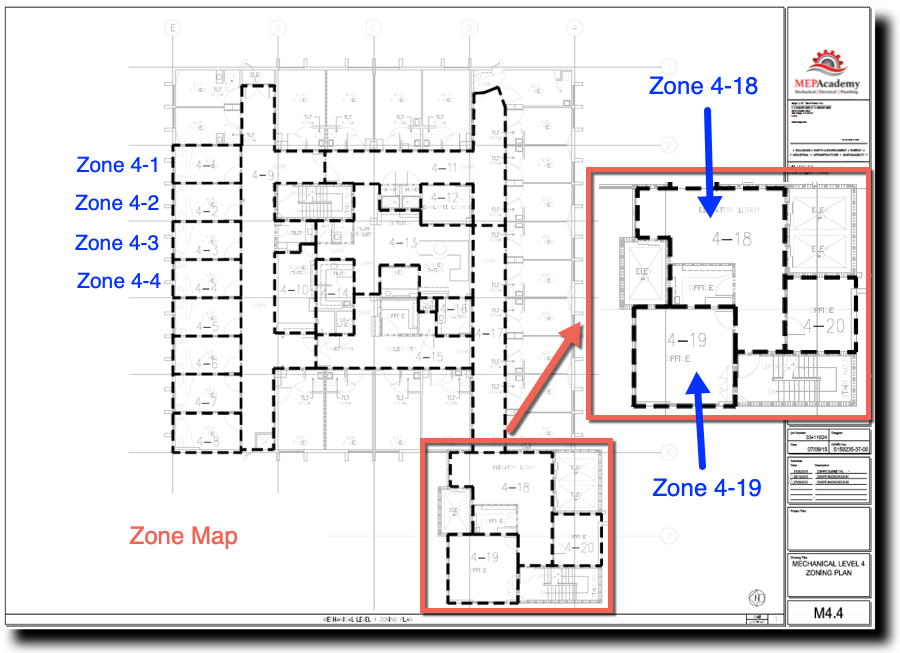
Zoning Map
This drawing shows how the HVAC zones are divided up. Each zone typically has its own controller or thermostat. You can see that the floor plan is separated with dashed lines indicating which areas or rooms share the same HVAC zone.
There are 20 zones on this zone map indicated as 4-1 through 4-20. These 20 HVAC zones could be served from one air handling unit. Each of the 20 zones can be served by a VAV (Variable Air Volume) terminal, that will vary the volume of air to the space based on the temperature of the room and the thermostat setting.
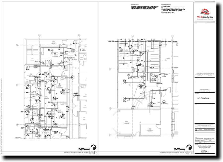
HVAC Floor Plan
The floor plan is a view from above, as if you were floating above the space.
This is where the sheet metal ductwork and HVAC Piping will be shown for each floor and area of the building. You might find that the HVAC Sheet Metal and the HVAC Piping are shown on separate drawings to allow for clarity and avoid having drawings that are congested and hard to read.
In addition to the floor plans for each floor in the building you will also have a Roof Plan that shows that portion of the HVAC system that is installed on the roof. Also, located on the plan view is a North arrow to provide building orientation (see plan view below for North arrow).
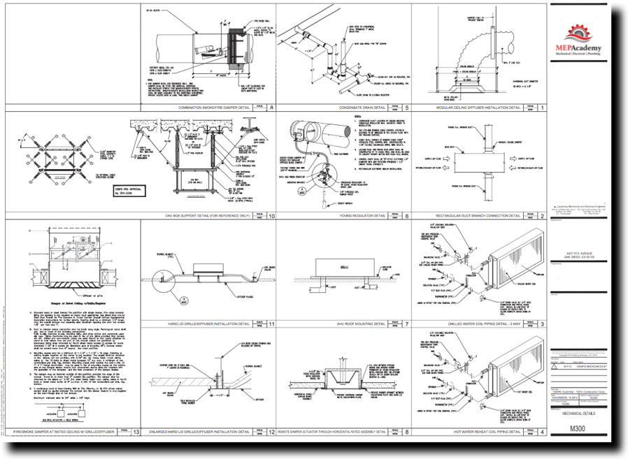
HVAC Detail Drawings
This drawing shows various HVAC details such as how equipment is supported, connected or provided with accessories.
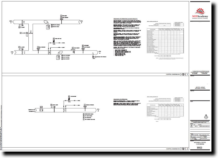
HVAC Controls Drawing
Most commercial HVAC systems provide some aspect of controls automation, except for the most basic system that may just have stand-alone thermostats. Control system vary in their sophistication based on the owners need to monitor the system and the size of the HVAC system. Large central plants will often have some form of BAS (building automation system) that optimizes the energy usage and schedule of the system.
Plumbing Drawings
You may need to check the plumbing drawings to confirm if certain scope has been shown on those drawings. Engineers will often put the condensate piping from air conditioners on the plumbing drawings, or the gas piping for a Gas/Electric HVAC unit.
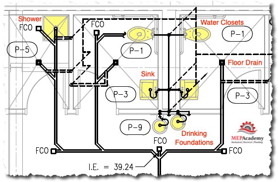
Since you are doing the Sheet Metal there might not be much if anything of your scope shown on the plumbing drawings except heater or boiler flues, but since you work for an HVAC company, it still falls under your company’s obligation to determine scope.
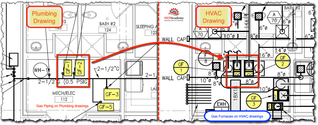
As shown in the above split image of the plumbing and HVAC drawings of the same area, the plumbing drawings have the gas piping that feeds the Gas Furnaces that are part of the HVAC scope of work. It’s important to clarify in your scope letter that you have excluded gas piping.
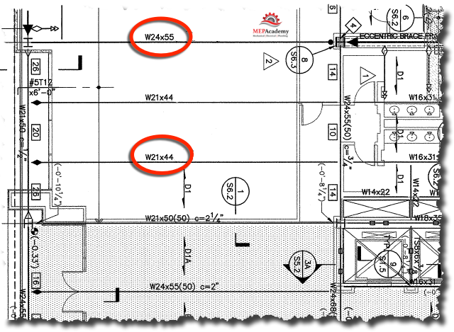
Structural Drawings
Looking at the structural drawings will sometimes provide you with information on supports for the mechanical equipment, ducts or piping. You can also determine how big the beams are and if there is enough room to possibly convert some of the more expensive rectangular ductwork into round duct.
Below is a small section of a structural drawings showing a large commercial buildings support beams. Just like other trades, the structural engineer uses means and methods to communicate information about the supports. The width and weight per foot of the beams are shown circled in red. The designation “W21 x 44”, means that the beam is 21 inches in depth and weights 44 pounds per foot. The “W24 x 55” is 24 inches in depth and weights 55 pounds per foot.
Demolition Drawings
When bidding on renovation projects there is a good chance that the existing HVAC system and ductwork will need to be removed or reworked. The engineer will provide a demolition drawing identifying which systems are to be removed or relocated. Typical anything with a hash mark through it will indicate an item to be removed, whether it’s a piece of equipment or a section of ductwork.
Drawing Revisions
When changes are made to drawings that have already been issued for bidding, the engineers will issue an addendum set of drawings for any updated changes made. These addendums usually cloud the areas on the drawings that have changed as indicated in the below image. In the image below the addendum is indicated as addendum #1 (see red circle around addendum symbol).
You would need to compare this addendum set to the original set of drawings to identify any changes that were made to the drawings. If you didn’t begin your takeoff or estimate on the previous set, then starting with this set of drawings would include the latest changes.
Several things to consider when working with an addendum set. First does the addendum set include a full set? Sometimes the engineer will only issue the drawings that have changes on them. This means that the addendum set may not be a full set. Check the list of drawings on the cover page or on the Architectural set. Be sure to identify all the drawings that you are bidding in your proposal.
Another thing to be aware of is that the engineers don’t always cloud the areas that have changed. This means that you will need to review the complete set for any changes that were made by the engineer but not clearly identified on the addendum set.
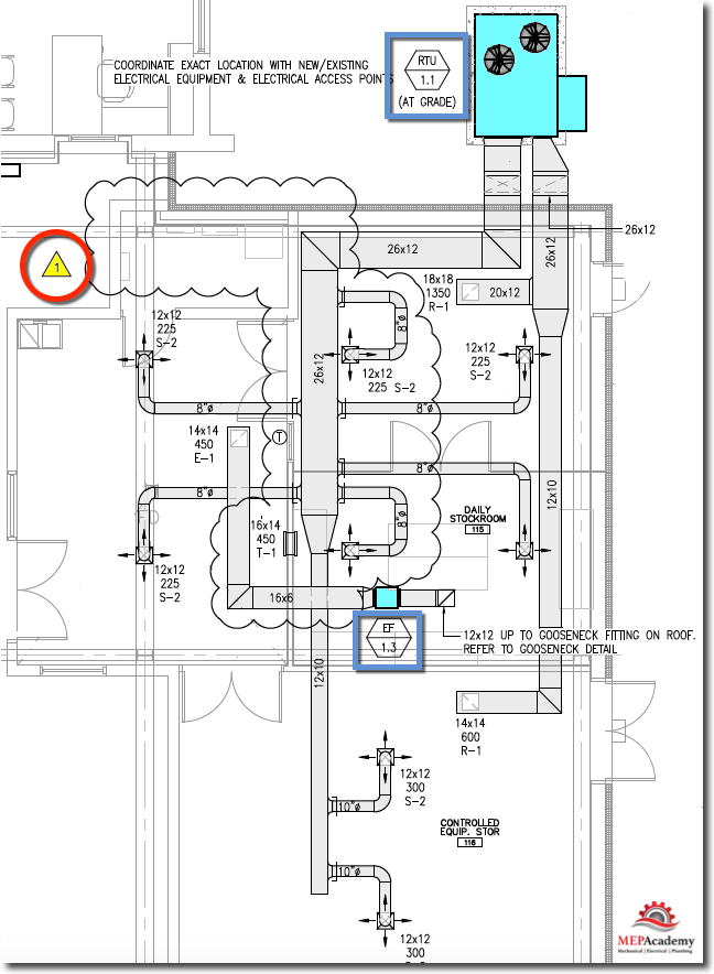
The drawing above also shows the equipment tags outlined by the blue squares. The first one is “RTU-1.1”, which stands for Rooftop Unit, but as can be seen in the drawing, this units is on the ground level. The next one is for “EF-1.3”, which is an Exhaust Fan.
Specifications on Drawings
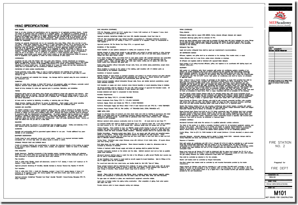
Some engineers prefer to put their specifications on the drawings instead of issuing a book of specifications. Below is an example where the engineer put all of the specifications on the front page (M101).
Now click the link below for Chapter #5 “Understanding HVAC Symbols” to get an overview of the road signs on the drawings that provide information in pictographs.
- Chapter #1 – General Layout of Drawings
- Chapter #2 – Architectural Drawings
- Chapter #3 – Plan, Elevation, Section Views and Details
- Chapter #4 – HVAC Mechanical Drawings
- Chapter #5 – Understanding HVAC Symbols
- Chapter #6 – Drawing Scales (How to Read Scales including Metric Scales)
- Chapter #7 – Sheet Metal Shop Drawings
