


Chapter #6 – Drawing Scales (How to Read Scales including Metric Scales)
It’s important that you understand how to read the various scales of architectural and engineered drawings. You will learn the following in this section.
- How to read an Architectural scale (mostly used for buildings in the U.S.). Architect scales, such as 1/4˝ = 1´-0˝ (1/48 size) or 1/8˝ = 1´-0˝ (1/96 size)
- How to read an Engineers scale (mostly used for roads and topographical measurements) Engineer scales, such as 1˝ = 10´ or 1˝ = 50´
- How to read a Metric scale (mostly used for buildings in other parts of the world)
- How to determine the scale of a drawing where the scale isn’t indicated
It’s not practical to draw a building to full scale, so various ratios are used to represent the actual size of the building. The scale provides a quick method for measuring drawn objects, such as the length of ducts, pipes, and electrical conduits.
The scale is usually shown in the lower right hand corner of the drawing or under the title of the page. There are often many different scales used in the same set of drawings, as they can be on floor plans, elevation pans, section views and details.
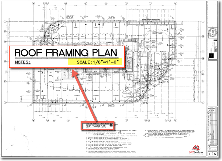
Often times you will find all three bits of information located together as in the above drawing and as shown in the insert below. The Title of the Drawing, the scale and the North arrow indicator.
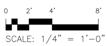
Bar Scale
The bar scale here is accurate even when reduced, so if your drawings have one of these all you have to do is put your ruler up to the scale bar and see which of the scales match exactly the numbers on the bar as shown below. If none match, then your drawings aren’t to scale and weren’t printed correctly.
Set your ruler so that the zero (0) on your scale aligns with the zero (0) on the bar scale, then check to see if the rest of the numbers line up exactly.
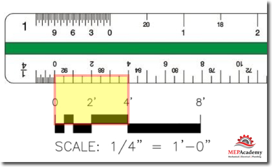
As seen above the zero’s (0) and the four’s (4) line up exactly between the ruler and the drawings bar scale, so you know you got the right scale. If they didn’t match, then you would try another scale on your ruler until you found one that did.
If there isn’t a bar scale, then there are other methods to confirm the drawings scale. It’s important to confirm you have the correct scale, otherwise all of your material lengths will be incorrect.
Determining the Scale when No Scale is Shown
Sometimes the scale is not shown on the drawings are is indicated incorrectly. By using some know distance like a doorway or the distance between columns, you can determine the true scale.
Everything on the drawing has been drawn to some scale so it’s a matter of finding something that you know the dimension of and laying your scale down next to it to find the right scale. For instance, most doors in our local area and in the U.S. are about 3 feet wide, so if you measure a doorway it will let you know the proper scale to use.
Checking the scale using the doorway and the 1/4″ = 1′-0″ scale.
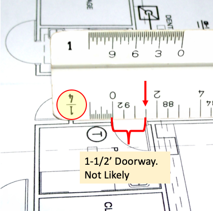
Looking at the above we can see that the doorway measures 1-1/2 feet on a 1/4′ scale. Unless this is a home for the 7-Dwarfs in the tale of Sleeping Beauty than the scale isn’t a 1/4″. Next we’ll try the 1/8″ = 1′-0″ scale as shown below.
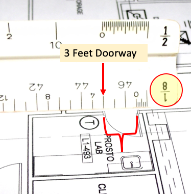
Using a 1/8″ = 1′-0″ scale gives a measurement of a 3 foot doorway, which is the correct dimension. This verifies that the correct scale to use is the 1/8″ scale.
You can also use a dimension that is already given on the drawings such as the width of a duct that has been drawn using double lines as shown below;
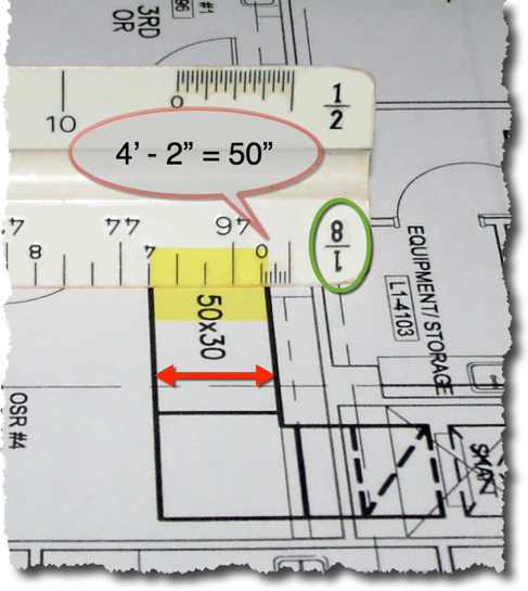
Using the dimension of the ductwork it is determined that the scale is 1/8″ = 1′-0″ as shown in the image above. The 50″ x 30″ duct measure 4′-2″ on our scale which is equivalent to 50 inches.
How to Use the Metric Scale (SI Units)
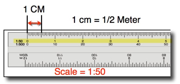
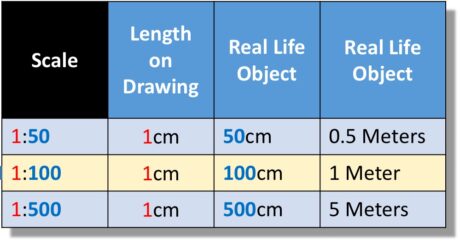
The Metric system is widely used around the world and on some Government projects, so it’s imperative that you understand both methods. The following scale is derived by measuring the drawings and multiplying every centimeter (cm) on the drawing by the denominator of the scale ratio such as 1:50 which means that for every 1 cm measured on the drawing it is equivalent to 50 cm in real life.
Basically the scale is represented by two numbers in a ratio, with the first number being how many centimeters are shown on your drawing followed by the second number which is separated by a colon (“:”), then the matching length of the real item to be built.
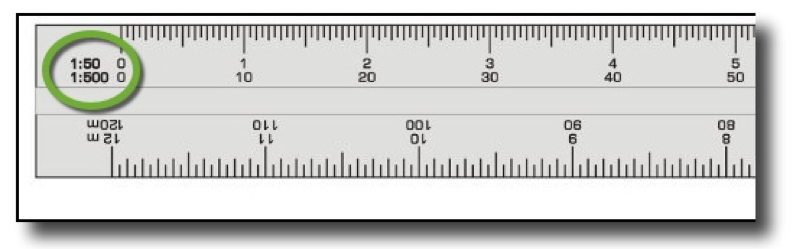
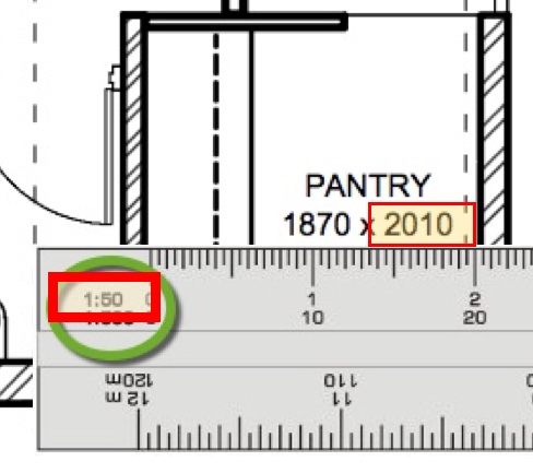
If we blow up the image of the scale, we see that there are two scales referenced at one end as opposed to the imperial version that showed 1/4” on the left side and 1/8” on the right side of the scale.
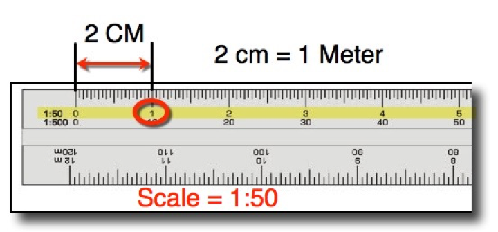
Metric Scale 1:50
The two scales shown are 1:50 and 1:500. What they represent is the following;
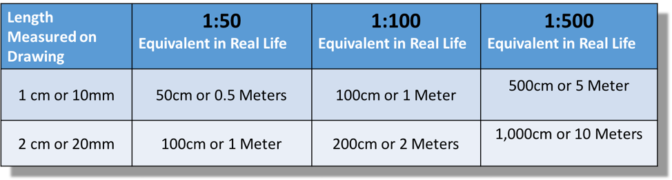
1:50 means that when you measure 1 cm on the drawing it is equivalent to 50 cm of the real item to be built. 1:50 is also equivalent to 1/2 of meter for every cm on the drawings, because 100 cm is equal to a 1 meter.
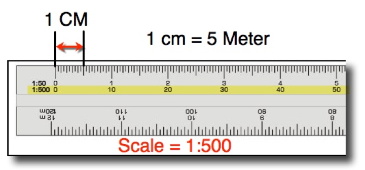
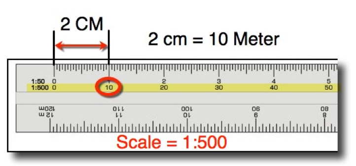
Metric Scale 1:500
Using the yellow highlighted 1:500 scale means that when you measure 1 cm on the drawing it is equivalent to 500 cm of the real item to be built. 1:500 is also equivalent to 5 meters for every 1 cm on the drawings, because 100 cm is equal to 1 meter; 500 cm is equal to 5 meters.
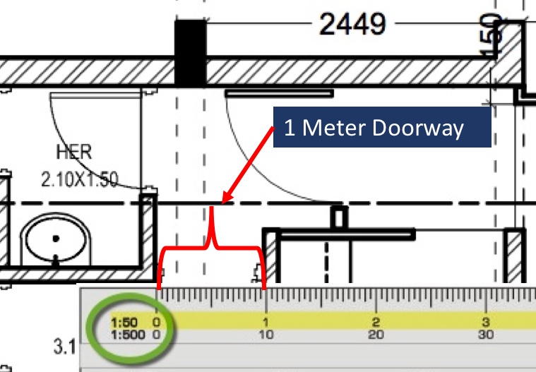
To verify that you have the correct metric scale you can use a Bar Scale or find a known dimension on the drawings and put your scale next to it until you get the correct scale.
Architectural Scale
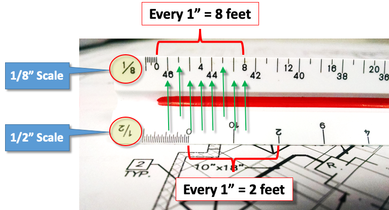
The most common scale in the USA is 1/8″ = 1′-0″ & 1/4′ = 1′-0″.
We will also show you how to verify that the scale indicated on the drawings is correct. Often times the engineer incorrectly marks the scale or no scale is indicated, so having a way to verify the scale is important to an accurate takeoff. The scale is indicated in various locations on the drawing. Each engineer has their own preferred location. The scale is often found under the floor plan or section name description as such;

Reading a manual scale is easy if you understand the basics of each scale size. As shown in the image below there are two scales on the same side of the same scale. The 1/8″ and 1/2″ scales are show on the same side.
Software Programs
If you own modern estimating software then the scale is set in the computer according to the scale indicated on the drawings. Occasionally the scale indicated on the drawings is incorrectly marked, so knowing how to confirm the scale is important.
There are also other programs like Blue Beam or Adobe that have various scale reading features of their software packages.
Next is Chapter #7 “Sheet Metal Shop Drawings” to see how drawings are prepared for use in the field.
- Chapter #1 – General Layout of Drawings
- Chapter #2 – Architectural Drawings
- Chapter #3 – Plan, Elevation, Section Views and Details
- Chapter #4 – HVAC Mechanical Drawings
- Chapter #5 – Understanding HVAC Symbols
- Chapter #6 – Drawing Scales (How to Read Scales including Metric Scales)
- Chapter #7 – Sheet Metal Shop Drawings
