


How a Power Factor Works.
We’ll learn what a power factor is, and how to correct a bad power factor. How to calculate the power factor. What causes a poor power factor, and what can be used to make the power factor better.
To watch the FREE YouTube version of this presentation, scroll to the bottom.
First, we’ll introduce the characters that are involved in calculating the Power Factor. There are three terms in addition to Power Factor that you need to know.
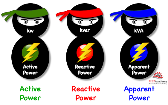
#1 We have the “Active Power” in (kw) which is the real electrical power required by motors, heaters, computers, ballast-based lights, transformers, etc. This active power is transformed into heat, light and mechanical energy. This is the work we want done in our buildings. Alias, Real power, True Power.
#2 We have “Reactive Power” in (kvar) which supplies the equipment in the building that uses magnetic circuits, like motors and transformers. This reactive power is what causes all the problems if not controlled, which will explain shortly.
#3 We have “Apparent Power” in (kVA) which is a result of the mix of the first two types of power. The larger the Reactive Power, the greater the Apparent Power. Will explain all these terms in greater detail. Alias, Total Power
#4 Is the “Power Factor” which is derived by dividing the “Active Power” into the “Apparent Power”. Kw/kVA
What is a Power Factor?
A power factor represents how efficiently a building uses the electrical power that the utility company provides. A power factor of 1 is the best factor, which represents 100% effective use of the power delivered. This is unlikely as there are factors that affect the quality of the power within a facility or building, such as induction motors.
Think of a power factor as a Grade given to a building by the utility company, like your teacher would give you a grade for a math or English class. The grade indicates how well the building uses the electrical power that the utility company provides, and the scale is 0 to 1, with 1 being the best factor or grade. You can think of it also as 0% to 100%, with 1 equal to 100%.
The possible punishment for a building that gets a bad grade or poor power factor is an extra fee charged on their utility bill and loss of additional kw capacity. This fee can add up to a large amount of money for a customer with a lot of induction load.
Power factors that are below 1.0 causes the utility company to generate more power to meet the demand. This causes an increase in the generation and transmission cost, which is passed on to the customer in the form of a reactive power (kvarh) fee or a percentage surcharge on their utility bill.
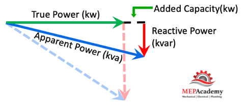
We can represent these three terms using a power triangle and demonstrate how reactive power effects apparent power.
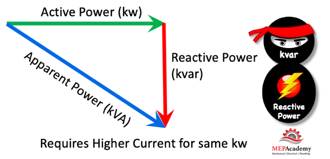
You can see using this power triangle that as the Reactive Power gets larger it requires more Apparent Power (kva) from the utility, but the Active/True Power remains the same. The true power (kw) is what the building needs to run its motors, and the reactive power is just making things more expensive for the utility company and the customer. The reactive power needs to be reduced or controlled as much as possible.
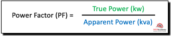
Power Factor (PF) = KW / KVA
The power factor is the True/Active power (kw) that the building requires to power its machinery divided by what the utility company provides in Apparent Power (kva). The power factor tells us how efficient the building is in using the power.
This means that the lower the reactive power the less the customer pays for apparent power (kva) to run their load (kw). Remember the utility must deliver the required apparent power (kva) even though the customer only needs the True/Active power (kw).
As an example, if a building required 1,000 KW of power and had a power factor of 100%, then it would only require 1,000 KVA of generating and distribution network capacity. If the power factor dropped to 80%, however, 1,250 KVA of capacity would be needed. The lower power factor has an adverse effect on generating and distribution capacity.
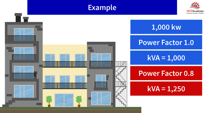
The lower the power factor the greater the burden on generation, distribution, and networks, due to excess KVA.
What Causes Reactive Power
Reactive power is caused by something that is found in just about every building, and that’s induction motors. Induction motors are required in every industry to perform work, so we can’t get rid of them, so there will always be some reactive power.
AC Induction Motors
The cause of all the problems begins with the AC (Alternating Current) motors. Induction motors use magnets that cause power quality issues. We need magnets to get motors started. If you have a lot of motors in a facility, like industrial buildings, then you’ll have a poor power factor unless something is done to correct it.
How to Correct Poor Power Factors
How does a building owner go about correcting their power factor to reduce wasted energy and cost, while increasing distribution and transformer efficiencies?
By adding capacitors to the system where induction motors are the main cause of the problem, the building can improve its power factor and network efficiency. The effect of Capacitance is opposite that of inductance.
Capacitors can be in various places within the electrical system to improve the power factor.
As this single line electrical diagram shows, power factor correction equipment can be located centrally (CPC) to handle the complete building, or regionally (RPC) within the building, or at individual Local (LPC) loads, such as motors.
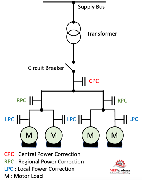
Locating the capacitor at the motor corrects any interference coming from the motor. If you have a lot of motors, then you might consider locating the capacitor at the service entrance switch gear to avoid having capacitors all over the facility.
Wherever the capacitor is located it will improve the power factor between that point and the power source. Remember that this means the power factor between the capacitor and the load or motor will remain unchanged.
Capacitance causes voltage to lead current, while inductance causes current to lead voltage.
Why Correct the Power Factor?
As we previously showed, the building can free up additional electrical capacity (kw), while reducing system losses in cables and transformers. These system losses heat up the electrical power lines which causes a loss in their capacity, as the reactive power contributes to those loses and thermal overloading. Improving the power factor reduces power loses, saves energy, and lowers the buildings overall CO2 emissions.
A poor factor (PF) will cause the line current to increase, causing losses in the distribution system and transformers. Even though the building uses the same Real Power, the lower factor (PF) cost the utility company more to generate and distribute.
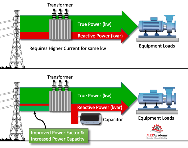
Having higher current requirements due to lots of Reactive Power could result in the overload of transformers, less available active power (kw), increased temperatures of electrical supply cables, higher voltage drops, increased energy consumption and cost. The building would require larger wiring, transformers, switches, etc., because of higher current and KVA.
Therefore, it’s important to correct Reactive Power by adding capacitors. The capacitors will produce reactive energy in opposition to the energy absorbed by induction loads such as those produced by magnets in motors. This is how Power Factor Correction is achieved. Basically, the capacitor is providing the reactive power required by the motor, so the utility doesn’t have to.
This will result in lower apparent power, improved power factor, increased capacity available, reduced power losses, and reduced cost to the building.
Increased Available Power (kw)
By increasing the power factor, you increase the available power (kw) for the facility. This is very useful if a building has reached its limit in the available power and needs to add additional power consuming devices.
Increasing the power factor (PF) by reducing reactive power (kvar) and maintaining the same apparent power (kva), a building can increase its (kw) usage capacity. Improving the factor free’s up additional capacity being wasted by reactive power. If you don’t choose to use the added capacity (kw), then your Apparent Power will be reduced along with the energy cost.
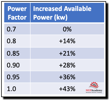
As the chart shows if a building has a power factor of 0.7 and increases it to 0.9 it increases the available power by 28%.
Savings on Electric Utility Bills
Utilities usually start charging a facility when their power factor drops below 0.90 to 0.95. The utility can charge based on the apparent power (kva) instead of the True/Active power (kw).
Buildings are charged for the circulation of Active Power over a period of time as indicated by kwh (kilowatt hours), while some utilities also charge for Reactive Energy over a period of time as indicated by kvarh (kilovolts-ampere-reactive hours). By improving the power factor, this charge will also be reduced or eliminated. The savings from the reduced charges can help pay for the added expense of making the improvements to the power factor.
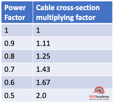
Reduction in Cable Sizing
By improving the power factor, less current is required, which means smaller conductors. A factor of 0.5 could require cross-sectional cable sizing twice that of a power factor of 1.0. As the table shows the increase in cabling size due to a worsening factor.
Reduction in Voltage Drop
The voltage drop will be improved upstream of where the capacitors are installed and avoids overloading the utility network.
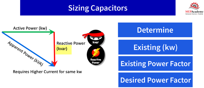
Sizing of Capacitors for Correcting Power Factor
To determine the size of a capacitor or the total kvar needed for a single load or entire power system we’ll need to determine the kw factor by gathering the following data: Actual Power (kw), existing and desired power factor.
With this information you can use an online calculator or manufactures chart to discover the required KVAR. The KVAR rating of a capacitor shows how much reactive power the capacitor will supply.
The formula is KVAR = kW x kW Factor
