The question customers often ask, is should I oversize my air conditioner?
We’re going to show you the difference between an air conditioner that is correctly sized and one that is oversized.
If you prefer to watch the video of this presentation, then scroll to the bottom.
Customers often think that a larger unit will cool their space more quickly, leading to immediate comfort. While it is true that an oversized unit will cool the air faster, it won’t run long enough to evenly distribute the cool air and effectively remove humidity, resulting in discomfort.
Comparison of Correctly sized to Oversized AC
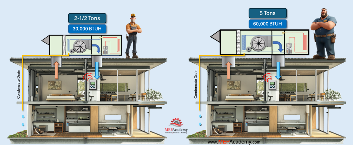
Here we have two air conditioners, one that is sized correctly at 2-1/2 tons, and another that is oversized at 5 tons. When the thermostat calls for cooling, they both turn on. While the larger unit has the capacity to cool twice as fast, the correctly sized unit will run longer to satisfy the space. You may think this is where the advantage of oversizing makes sense by having a larger unit run for less time. We’ll show you why this is a bad idea.
We have added blue colored dots to represent the moisture level and what happens to the humidity or moisture in the conditioned space when the air conditioner is running. When the air conditioner is running, we can see that moisture is being removed from the air as water begins dripping out of the condensate drain line. The drain line is often out of sight of the occupant who is unaware of its existence unless it becomes clogged and causes a problem.
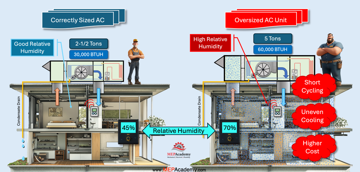
The oversized unit cools the space so quickly that the air conditioner shuts off before removing enough moisture. We can see the correctly sized unit keeps running while the larger unit has shutoff. The smaller unit runs longer, allowing more time for the moisture in the air to meet the cooling coil and condense out as water. The longer the unit runs the more moisture that is removed from the air, making the air less humid and stuffy.
Oversizing an air conditioner can lead to several issues that can negatively impact both the system’s performance and the comfort of the space being cooled. Here are some key reasons to avoid oversizing an air conditioner:
Short Cycling
An oversized air conditioner will cool the space too quickly, causing the system to cycle on and off frequently. This short cycling leads to increased wear and tear on the unit, reducing its lifespan and increasing maintenance costs.
Inadequate Humidity Control
Air conditioners not only cool the air but also remove humidity or moisture. The air contains moisture that isn’t visible to the human eye. Proof of this moisture becomes visible on a hot day with a glass full of ice water. The moisture in the air condenses on the cool outer surface of the glass.
This moisture comes from the surrounding air and not from the ice in the glass. An oversized unit will cool the air so rapidly that it won’t run long enough to remove this moisture or dehumidify the space effectively, leading to higher indoor humidity levels. This can result in a clammy, uncomfortable environment and promote the growth of mold and mildew.
Why is removing moisture from the air so important?
The human body cools itself primarily through the process of sweating and subsequent evaporation of sweat from the skin’s surface. High humidity levels in the environment can slow down the evaporation process because the air is already saturated with moisture. This makes it harder for sweat to evaporate, reducing the cooling efficiency.
Increased Energy Consumption
Frequent cycling and running at a higher capacity than needed will consume more energy, leading to higher utility bills. An oversized unit is less energy-efficient compared to a properly sized one.
Uneven Cooling
Oversized air conditioners can create hot and cold spots within the space. The rapid cooling cycle may not allow the conditioned air to be distributed evenly, leading to some areas being too cold while others remain warm.
Higher Initial Cost
Larger units are more expensive to purchase and install. By properly sizing the air conditioner, you can avoid unnecessary costs and ensure you are investing in the right equipment for your needs.
Environmental Impact
Higher energy consumption results in increased greenhouse gas emissions, which contribute to environmental degradation. Properly sizing an air conditioner helps reduce the carbon footprint of the building.
To determine the correct size for an air conditioner, a detailed load calculation should be performed. Consider factors such as the size of the space, insulation levels, number of occupants, and local climate. This ensures that the system operates efficiently, provides adequate comfort, and maintains a healthy indoor environment.