Dry Bulb Temperature and Wet Bulb Temperature are both essential in understanding air properties, especially in HVAC applications. We’ll explain these two temperatures and how they relate to evaporative cooling and relative humidity using a psychrometric chart.
If you prefer to watch the Video of this presentation, then scroll to the bottom of this page.
Dry Bulb Temperature
Dry Bulb is the temperature of the air measured by a regular thermometer, without considering moisture. It’s measured using a standard thermometer exposed to the air but shielded from direct solar radiation. Dry bulb temperature is what people commonly refer to as “air temperature.” It indicates the heat level of the air and is crucial for thermal comfort and HVAC system design.
When trying to understand the current air conditions, one must also look at the wet bulb temperature, not just the dry bulb temperature, as it accounts for humidity and provides a more complete picture of heat stress and cooling potential.
Wet Bulb Temperature
Wet Bulb is the temperature a parcel of air would have if cooled to saturation (100% relative humidity) by evaporation. The wet bulb temperature will always be lower than or equal to the dry bulb temperature because evaporation absorbs heat. It’s measured by wrapping a wet wick around a thermometer bulb and allowing evaporation to cool the bulb, with the resulting temperature reflecting the cooling effect of moisture in the air.
As water evaporates, the temperature drops, and this lower reading is the wet bulb temperature. Wet bulb temperature helps assess the amount of moisture in the air. It is used in processes like evaporative cooling and determines the cooling efficiency in such systems.
Wet Bulb Depression
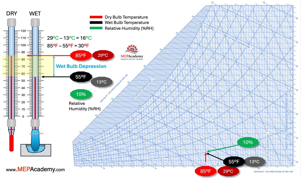
The Wet Bulb Depression is an indicator of how much the air can cool down through the process of evaporation. The larger the temperature depression, the drier the air, which means it has more capacity to absorb moisture.
We can see on this psychrometric chart that a dry bulb temperature of 85 Fahrenheit minus the wet bulb temperature of 55 Fahrenheit equals a wet bulb depression of 30 Fahrenheit or 16 Celsius
Wet Bulb Depression = Dry Bulb Temperature – Wet Bulb Temperature
A high Wet Bulb depression means that there is significant potential for evaporative cooling. For example, in hot, dry environments, where the Dry Bulb Temperature is much higher than the Wet Bulb Temperature, evaporative cooling (like using a swamp cooler) is very effective.
A low Wet Bulb depression (where Dry Bulb Temperature is close to Wet Bulb Temperature) indicates the air is near saturation with moisture, so there is less cooling potential through evaporation.
Relative Humidity (RH)
Relative Humidity is the percentage of moisture the air holds compared to the maximum it can hold at that temperature. When the Dry Bulb Temperature and Wet bulb temperature are close together, the relative humidity is high because less evaporation is occurring. When Dry Bulb and Wet bulb temperatures are far apart, the air is dry, and relative humidity is low, as there is more capacity for moisture to evaporate into the air.
We can see that the relative humidity is at 10%.
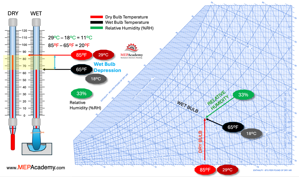
If the wet bulb temperature increased to 60 F or 15 C, then the wet bulb depression decreases to 25For 14C. We can see that the relative humidity has increased to 20%.
If the wet bulb keeps climbing and the dry bulb stays the same, the wet bulb depression keeps shrinking, while the relative humidity increases. This informs us that as the wet bulb gets closer to the dry Bulb Temperature the relative humidity increases. For efficient use of a swamp cooler or evaporative cooler, a wet bulb depression of at least 15°F to 20°F (8°C to11°C) or more is generally required. This means the difference between the dry bulb temperature (ambient air temperature) and the wet bulb temperature should be at least 15°F (8°C), indicating low enough humidity for effective evaporation and cooling. Evaporative cooling is best suited for hot, dry climates with low humidity.
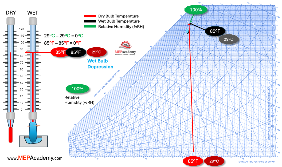
Here the dry bulb and wet bulb temperatures are the same at which point we have 100% relative humidity, and we have also reached the dew point line where condensate occurs. The wet bulb depression is zero because the dry bulb and wet bulb temperatures are the same.
Dew Point Temperature
Dew point is the temperature at which air becomes fully saturated (100% Relative Humidity) and moisture condenses into liquid (dew). If Dry Bulb Temperature falls to the dew point temperature, condensation occurs, leading to dew or fog. When the Wet bulb temperature is close to the DBT, the air is near saturation, and the dew point is close to the current temperature, meaning high humidity levels.