In HVAC water-based systems, water distribution is critical to ensure that each terminal unit receives the correct amount of heated or cooled water. Two popular piping configurations, Direct Return and Reverse Return, are often used in these systems. Each configuration has its unique benefits, potential drawbacks, and implications for water balancing and system performance. Here, we’ll break down the differences between these two types of piping layouts, discuss their impact on water balancing, and examine the pros and cons of each.
if you prefer to watch the video of this presentation, then scroll to the bottom.
What is Direct Return Piping?
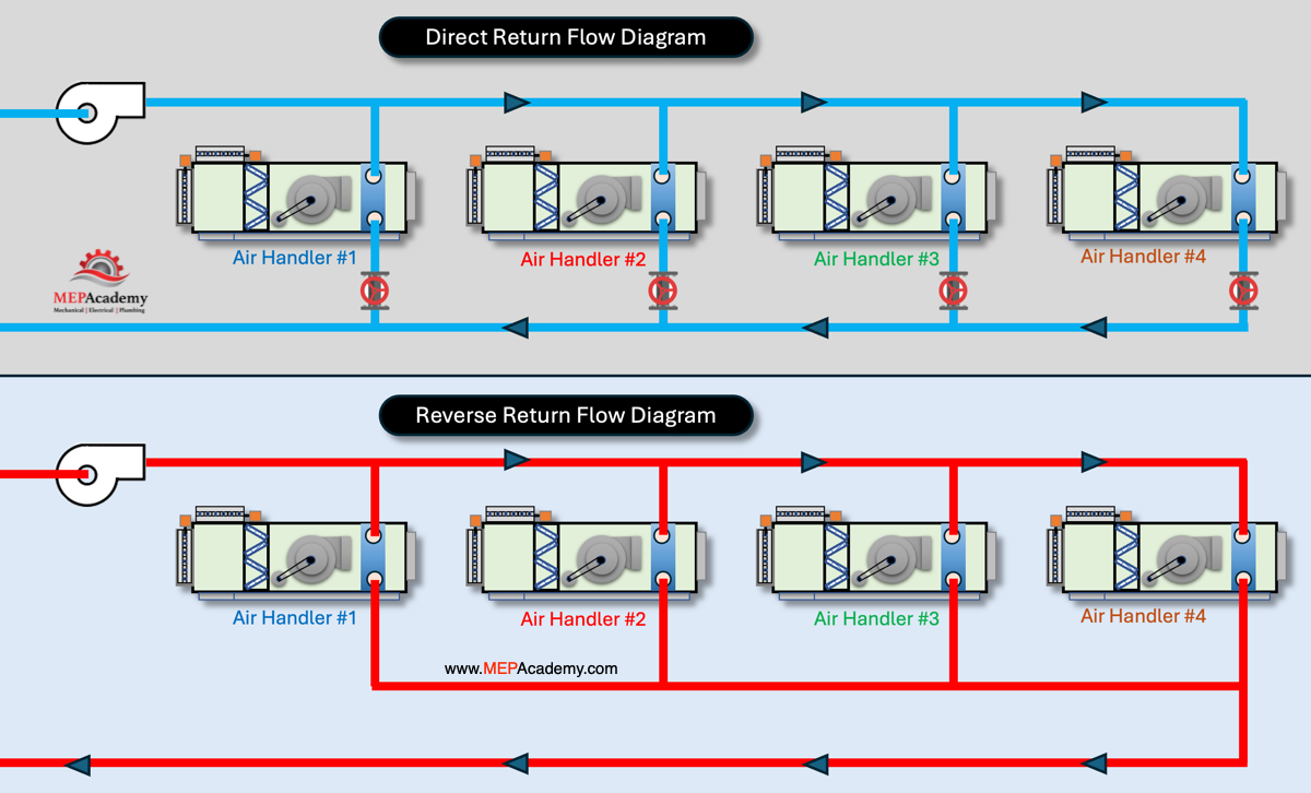
In a Direct Return Piping system, water flows to each air handler coil and returns along the shortest path. This means that the closes air handlers coil to the heating or cooling supply source, such as a boiler or chiller, will have the shortest overall piping length, while the furthest air handler will have the longest piping route.
Since the closes air handlers have less piping, they’ll have less pressure drop, considering the pressure drop for all coils are the same. This creates different pressure drops for the piping circuits to and from each air handler, which creates a water balancing issue. This is why balancing valves are often added to create additional pressure drops to equal out each piping circuit.
Direct Return is often considered simpler and more cost-effective to install, as it requires less pipe and can be laid out with fewer complex fittings.
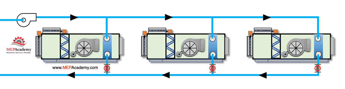
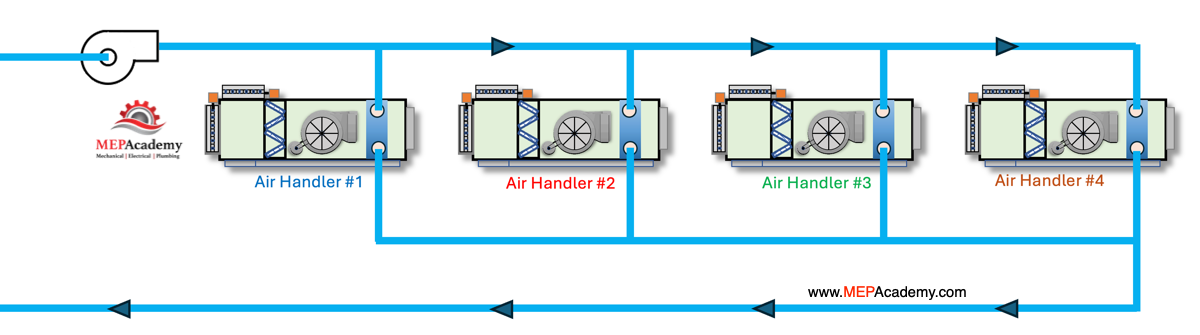
The layout can differ with all coils in a straight line like this piping diagram which makes it easier to see just how this works. If the pump is cycled on and the water flows through the system, the water molecules leaving the chiller at the same time will reach each air handler coil at different times. If you must run 50 feet and your competition must run 100 feet, you will easily return to the finish line first. The closest coils will get fed first, while the farthest coil will receive chilled or heated water last.
What is Reverse Return Piping?
In a Reverse Return Piping system, water flows to each terminal unit via the shortest path but returns along the longest path. Essentially, the return pipework is designed so that the last unit on the supply line is the first to return to the source. This approach results in equalized pipe lengths for each terminal unit, which is one of the defining characteristics of Reverse Return piping.
The theory is that each air handler will have the same distance from the source and back which would make their pressure drops equal and balancing valves not required. In theory maybe, but air handler zone differences can affect the pressure drop through each coil as each control valve adjust flow for their current zone demand.
Here we can see that all the water leaving the chiller will return from each air handler to the chiller at approximately the same time as the total round trip piping length is the same distance.
Here is another look at a reverse return where the air handlers are set in a straight line with equal lengths of pipe from the chiller to the coil and back to the chiller. The water for each air handler arrives at different times, but the total length is the same overall, which balances out the pressure drop in a perfect world.
We can see that with the direct return piping layout the water returns to the source much quicker that the reverse return piping layout. The reverse return piping distance for the water to travel is much longer than the direct return method.
Piping Differences
In a Direct Return system, the main pipes remain the same size along the entire supply and return runs until they reach a section where the flow decreases, and a size reduction is needed. This is simpler compared to a Reverse Return system, where the design often requires a gradual reduction in pipe size along the return path as flow is picked up from each terminal unit. This consistency in sizing throughout most of the Direct Return system reduces complexity and makes both material handling and installation faster and easier.
Here are the main ideas to remember about Direct Return vs. Reverse Return piping systems:
Direct Return Piping
Simpler Installation: Main pipes stay the same size until a reduction is necessary, streamlining material handling and installation.
Shorter Total Pipe Length: Typically requires less piping, saving on material costs and installation time.
Imbalance in Flow: The unequal pipe lengths to each terminal unit create varying flow resistances, making water balancing more challenging.
Higher Maintenance: More frequent adjustments and use of balancing valves are needed to ensure consistent flow rates.
Lower Initial Cost: Installation is generally less expensive due to reduced pipe material and labor.
Reverse Return Piping
Naturally Balanced Flow: The design ensures equal pipe lengths to and from each terminal unit, aiding in consistent flow and easier balancing.
Higher Installation Cost: More piping material and complex routing increase initial costs and installation time.
Longer Total Pipe Length: Requires additional piping to loop back the return path, impacting space and cost.
Reduced Maintenance: Less need for frequent adjustments due to the self-balancing nature of the system.
These points highlight the trade-offs between the simpler, cost-effective Direct Return and the more balanced but costlier Reverse Return systems.