


 Overrides: Risks, Failures, and Best Practices")


How to Read Wiring Diagrams in HVAC Systems. There are various types of wiring diagrams used in the HVACR Industry. We’ll explain how to read a schematic wiring diagram and what the various symbols represent and how they function.
If you prefer to watch the Video version of this presentation you can scroll to the bottom or click on this link “How to Read HVAC Electrical Wiring Diagrams”.
Wiring diagrams are used for the installation of the HVAC equipment, trouble shooting, or locating an electrical device in the control panel or within the unit. There are differences between the type of diagrams based on what they’re used for.
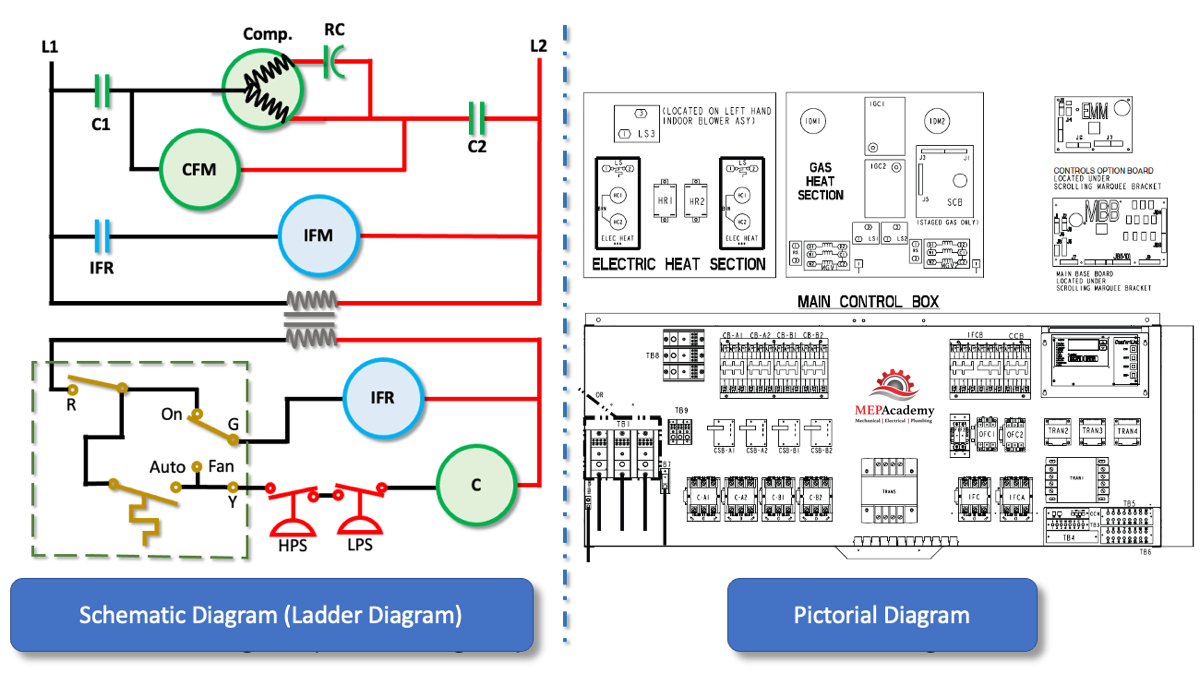
The installation diagram will show those connection points most important for connecting the electrical power to the HVAC equipment, while the internal wiring diagrams are meant for troubleshooting by technicians. There is a pictorial diagram that gives a much more cluttered look at the electrical components and wiring as its intended to give you the proximity of the component within the unit.
We’ll jump right into showing you a schematic diagram for a simple air conditioning unit.
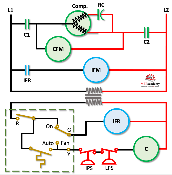
We’ll make a ladder diagram using a simple air conditioner as our example. First we have the main electrical supply lines L1 and L2 providing 208/230 volt, single phase power. Then we’ll need a transformer to provide 24 volt low voltage power for our thermostat, switches and relays. Next we add a thermostat to control the air conditioner, and we connect the power from the low voltage side of the transformer to the “R” terminal of the thermostat.
We’ll need to add an indoor fan motor connection to the line voltage side of the diagram and provide contacts for turning on and off the fan. Next we add the refrigerant compressor to the line voltage side and include contacts and a run capacitor.
To complete our refrigerant circuit we need to add an outdoor condenser fan motor on the line voltage side of the diagram. This provides us with the three largest energy consuming devices in our air conditioner, the compressor, condenser fan and indoor fan motors.
Now we need to add some way to control these three motors, which we’ll do from the low voltage side and the use of the thermostat. First we’ll add a compressor relay on the low voltage side of the wiring diagram. This relay will communicate with the compressors contactors on the line voltage side of the wiring diagram as required to start and stop the compressor.
Also included are some safety devices to protect the compressor from high and low pressure conditions. There is a High Pressure Switch that will shut off the compressor if the pressure in the refrigerant system gets too high. Likewise there is a low pressure switch that will shut off the compressor if the pressure in the refrigerant system gets too low. These safety devices do this by cutting off the low voltage power to the relay coil, which in turn opens the contacts on the line voltage wiring feeding the compressor and outdoor fan. We need to do the same thing for the indoor fan, so we’ll add a relay coil that will open and close a set of contacts on the line voltage side that feeds the indoor fan motor.
Looking at the thermostat we can see that if we move the fan switch to “Auto” then the thermostat will cycle on and off the compressor and indoor fan motor. If we put the fan switch to “On” then low voltage power is always provided to the indoor fan relay, which means that the fan will run all the time, even when the compressor is off.
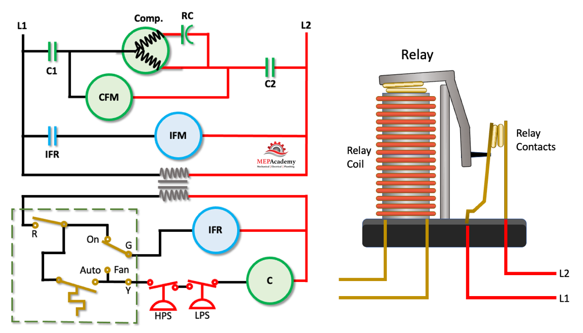
Let’s look at how the symbols on the diagram relate to actual physical, real world items. This is what an electrical relay might look like without it’s protective cover. We have two relays in our diagram, the Compressor and Indoor Fan Relays. The relay has two main parts, the coil, which is located on the low voltage side of the diagram, and the contacts, which are located on the line voltage side.
When the thermostat is on, low voltage power will be running through its wires energizing the coils of the relays for the indoor fan and compressor. The relay coil will cause the contacts to close which allows line voltage power to energize the compressor, condenser fan and indoor fan motors. When the thermostat is off the coil is de-energized and the contacts open, turning off the compressor and fans. Again, if we energize the coil the contacts close to start the compressor and fans.
We have the pictorial wiring diagram and the schematic wiring diagram. The schematic wiring diagram is also known as a ladder diagram. This is due to its arrangement of vertical lines on each side of horizontal lines which are comprised of electrical components.
This is a pictorial representation of what the electrical components look like when looking directly at the internal control board. This lets you see where the parts are located, but it’s not as useful for troubleshooting as the schematic ladder wiring diagram we just looked at. The relays are shown as blocks just as the transformers are. This allows us to easily find them within the HVAC equipment, but doesn’t give us a good way of troubleshooting a problem.
Schematic Diagram
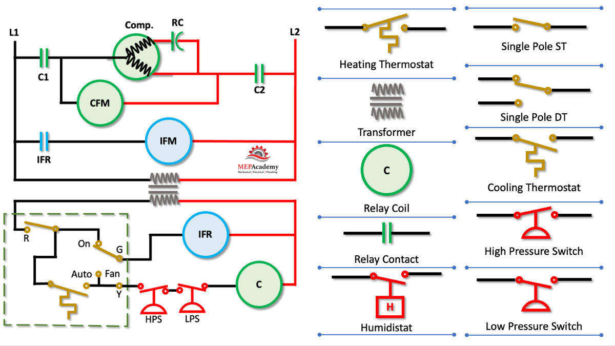
The service technician needs to be able to read the wiring diagrams in order to troubleshoot problems. The quickest and less cluttered diagram is the schematic diagram, which shows system functionality without the clutter. The schematic diagram is designed in a ladder format, where line voltage L1 and L2 are shown as vertical lines, and all the electrical components shown on horizontal lines. The lines represent electrical wires while the various symbols are used to represent electrical components, from relays and contacts, to transformers, motors and compressors. There should be a legend that identifies what each symbol represents.
There are symbols for the various types of switches including thermostats and pressure limiting devices. There are symbols for Relays and their corresponding contacts that energize or de-energize circuits. The contacts are shown on the diagram as they would be normally without any electrical power being supplied. You can see that all of our example contacts are what is called normally open, meaning with no power they are set to be open. When a contact is open, no electrical power can flow through it.
Electrical circuits can flow in series which means there is only one path for electricity to flow or they can be parallel circuits which allow multiple paths for the electricity.
Once the technician has reviewed the schematic wiring diagram and has a suspicion of the part causing the problem, the pictorial diagram can be referenced to see where that part is located in the unit.
By looking at the schematic wiring diagram the technicians can see how the piece of equipment should be operating by following the modes of operation. If the controller calls for cooling or heating, they should be able to see how the schematic diagram components will be activated to bring on and off the system, along with safety devices that protect the equipment. The schematic diagram allows for a quick view of how the system should operate and allows for troubleshooting any problems.
The technician will find the wiring diagrams attached to an access panel, electrical cover or housed within a internal pocket.