When buying a car, you might look at how many miles per gallon the car can achieve when comparing which car is more efficient. This is an indication of its ability to convert fuel into a certain distance traveled. A similar ratio in the HVAC industry is used to indicate how efficient an air conditioner or heat pump is at using electricity to produce BTU’s.
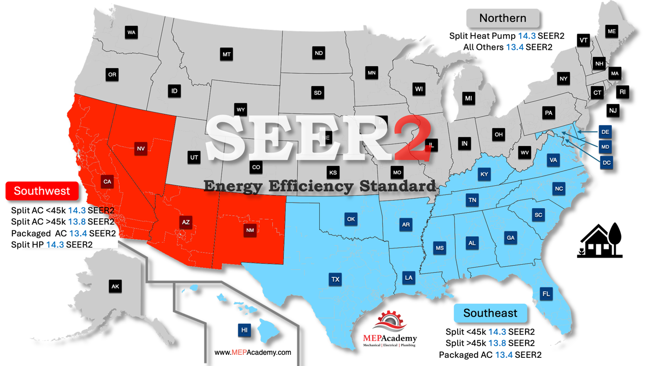
Beginning on January 1, 2023, the US Department of Energy (DOE) has changed to a new rating system where different regions of the United States are divided up. There are now Northern and Southern regions with varying efficiency ratios. Any air conditioners installed starting in 2023 and after in the Southwest and Southeast regions of the United States must meet the new SEER2 energy efficiency standard.
SEER2 Energy Efficiency Standards Map
Regions matter because different standards are based on the climate needs of customers living in the North, Southeast, and Southwest regions. People in southern climates, where air conditioners are used more frequently, require more energy-efficient systems. Therefore, depending on your geographical region and HVAC needs, split system air conditioners, heat pumps, and single-package systems may have varying efficiency standards.
Energy Efficiency Ratio (EER)
The Energy Efficiency Ratio (EER) measures the efficiency of an air conditioning system or heat pump. It indicates how effectively the unit converts electrical energy into cooling output. Specifically, EER represents the ratio of the cooling capacity (in British Thermal Units per hour, or BTU/h) to the power input (in watts) at a given operating condition.
EER Calculation
EER = Cooling Capacity (BTU/h) / Power Input (W)
EER is typically measured under specific conditions: an outdoor temperature of 95°F, an indoor temperature of 80°F, and 50% relative humidity. This standardization allows for a direct comparison of different units under the same conditions.
Seasonal Energy Efficiency Ratio (SEER)
The Seasonal Energy Efficiency Ratio (SEER) measures the overall energy efficiency of an air conditioning system or heat pump over an entire cooling season. Unlike the Energy Efficiency Ratio (EER), which is calculated at a single operating condition, SEE considers the variations in temperature and cooling demand that occur throughout the season. It represents the ratio of the total cooling output (in BTUs) to the total electrical energy input (in watt-hours) over the cooling season.
SEER Calculation
SEER = Total Cooling output over a Season (BTU) / Total Electric Energy Input over a Season (Wh)
SEER ratings provide a standardized way to compare the energy efficiency of different air conditioning units and heat pumps, considering the varying cooling demands throughout the cooling season. This helps consumers and professionals make informed decisions when selecting HVAC equipment for energy efficiency and cost savings.
Heating Seasonal Performance Factor (HSPF)
The Heating Seasonal Performance Factor (HSPF) measures the efficiency of heat pumps in heating mode over an entire heating season. It represents the ratio of the total heating output (in British Thermal Units, or BTUs) to the total electrical energy input (in watt-hours) during the heating season. HSPF provides an indication of how efficiently a heat pump converts electricity into heat over a range of conditions and temperatures experienced throughout the heating season.
HSPF Calculation
HSPF = Total Heating Output (BTU) / Total Electric Energy Input (Wh)
HSPF provides a comprehensive measure of a heat pump’s heating efficiency over a typical heating season, helping consumers and professionals make informed decisions about equipment that offers better energy savings and performance in various climates.
The new SEER2 Standards
The calculation for SEER2, like the original SEER, is designed to measure the overall energy efficiency of an air conditioning system or heat pump over a cooling season. While the fundamental formula remains similar, SEER2 incorporates updated testing conditions and procedures to better reflect real-world performance.
SEER2 Calculation
SEER2 = Total Cooling Output (BTU) / Total Electric Energy Input (Wh)
Key Differences in SEER2 vs SEER Calculation:
1. Updated Testing Conditions
SEER2 includes more representative testing conditions that reflect a wider range of operating environments and load profiles, considering part-load and variable load conditions more accurately.
2. Improved Measurement Techniques
SEER2 employs updated measurement techniques to account for variations in system performance, cycling losses, and other factors that impact efficiency under real-world conditions.
3. Standardized Load Profiles
SEER2 uses standardized load profiles that mimic the fluctuating cooling demands typical of an entire cooling season, offering a more comprehensive assessment of system efficiency.
Example Calculation
If an air conditioning system provides 60,000 BTUs of cooling over a season and consumes 4,000 watt-hours (Wh) of electricity during that time, the SEER2 would be calculated as follows:
SEER2 = 60,000 BTU / 4,000 = 15
Application
Regulatory Standards: SEER2 is used to set minimum energy efficiency standards for new HVAC systems, ensuring they meet contemporary performance requirements.
Product Comparison: Consumers and professionals can use SEER2 ratings to compare the efficiency of different air conditioning units and heat pumps, aiding in the selection of more energy-efficient models.
Energy Savings: Higher SEER2 ratings indicate better energy efficiency, which translates to lower energy consumption and cost savings over the cooling season.
By incorporating more realistic testing conditions, SEER2 provides a more accurate measure of an HVAC system’s seasonal energy efficiency, helping to promote the use of systems that are more efficient and environmentally friendly.
Uses of EER, SEER and HSPF
Performance Assessment: These calculations offer a standardized way to compare the efficiency of different air conditioners or heat pumps. A higher value indicates better energy efficiency.
Energy Cost Savings: HVAC Equipment with higher ratings use less electricity to produce the same amount of heating or cooling, leading to lower energy bills.
Environmental Impact: More efficient air conditioners or heat pumps reduce overall energy consumption and greenhouse gas emissions, contributing to environmental sustainability.
Regulatory Compliance: In many regions, building codes and energy standards specify minimum efficiency ratio requirements for air conditioners and heat pumps. Compliance with these regulations ensures that installations meet energy efficiency standards.
In this article we’ll cover how to calculate cubic yards of excavation and backfill, soil types, excavation equipment, soil testing, compaction, swell factor, the difference between excavating and trenching, and when shoring or trench supports are required.
First let’s cover a few very important items that need to be done before any digging begins.
If you prefer to watch the video of this presentation, then scroll to the bottom.
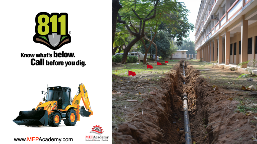
Call 811 before Digging
The first thing to do is call 811. Calling 811 before digging is crucial because it helps identify and locate underground utilities such as gas lines, water pipes, and electrical cables. This free service coordinates with utility companies to mark the locations of these buried lines, preventing accidental damage that can cause service disruptions, costly repairs, and serious safety hazards such as gas leaks or electrical shocks.
Call 811 before any digging begins to get notified of any known underground utilities.
By calling 811, individuals and contractors ensure compliance with safety regulations and protect themselves, their property, and the community from potential dangers associated with unmarked utilities.
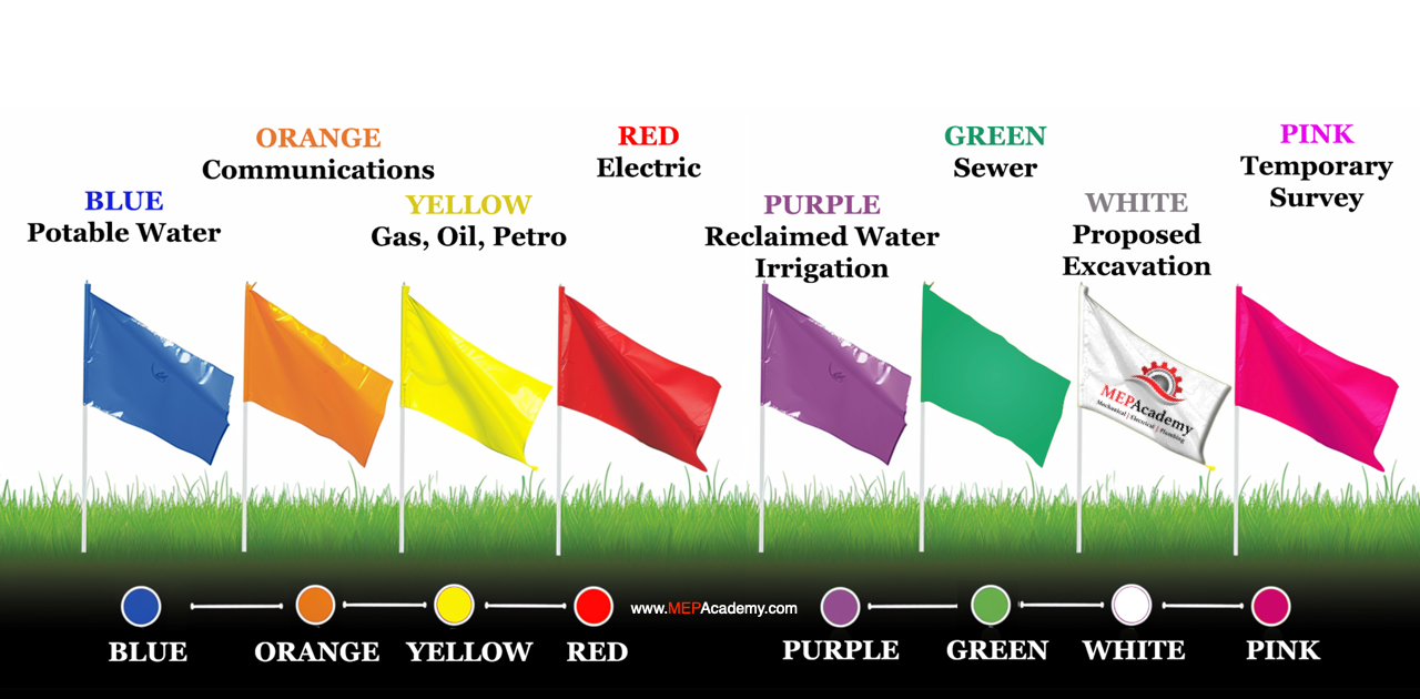
APWA Color Coding
Using the American Public Works Association (APWA) color coding system to mark your site before excavating ensures clear and standardized communication of underground utility locations. This system assigns specific colors to different types of utilities, such as red for electric power lines, yellow for gas, oil, or steam, and blue for potable water.
American Public Works Association color chart for marking excavations
By using these color codes, you help prevent utility damage, reduce the risk of accidents, and comply with industry best practices and regulations, ensuring a safer and more efficient excavation process. A white mark is used to outline the proposed route of the excavation. These markings can be on the surface or with flags and stakes used to increase visibility.
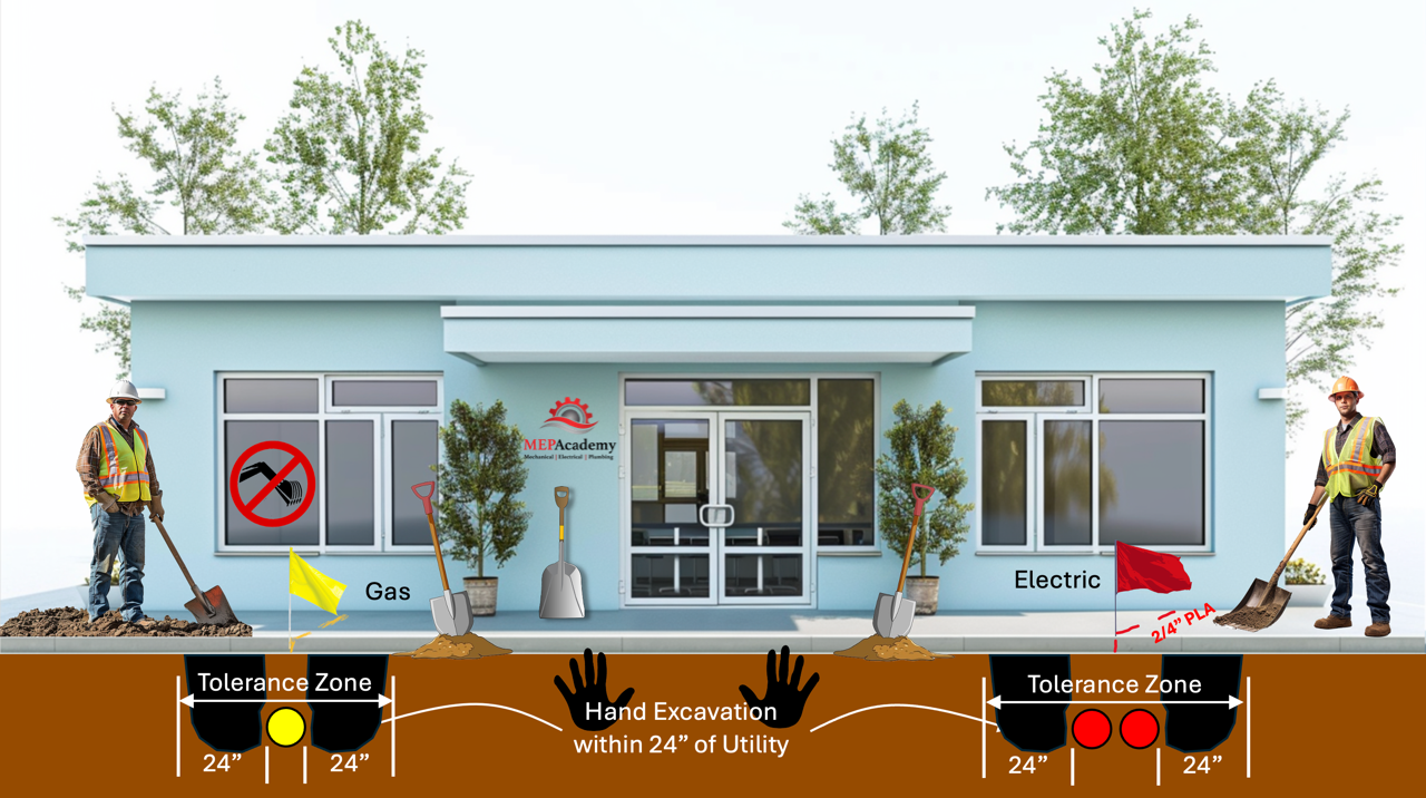
Tolerance Zone
The tolerance zone is a safety buffer zone around existing underground utilities within which excavation must be conducted with extra caution. Typically, it extends 18 to 24 inches (45 to 60 centimeters) from each side of a marked utility line. Within this zone, hand digging or using non-invasive methods like vacuum excavation is required to avoid damaging the utilities. Adhering to the tolerance zone helps prevent utility strikes, ensuring the safety of workers and the integrity of underground infrastructure.
Tolerance Zone when excavating near existing utilities
One of the first steps is to determine the Soil type.
Soil Classifications
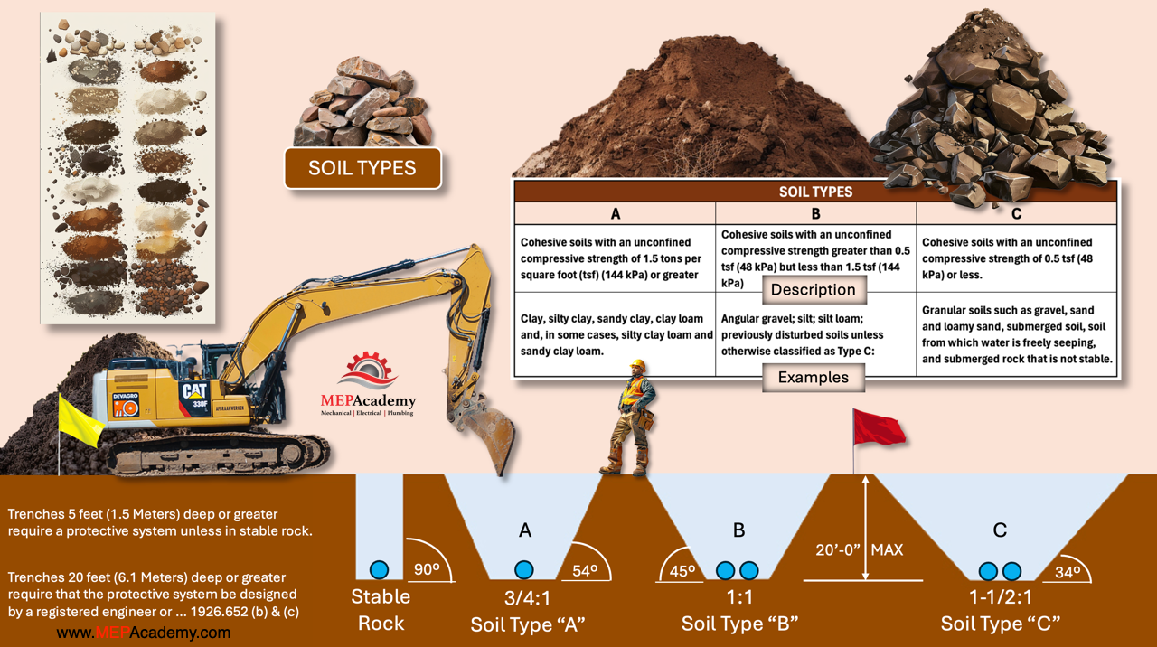
OSHA (Occupational Safety and Health Administration) classifies soils into three main categories—Type A, B, and C—based on their stability and cohesiveness, which is critical for ensuring safety during excavation work. The soil type must be identified by a competent person as defined by OSHA. Here are the definitions and purposes of these classifications:
Soil Types and their Sloping Requirements per OSHA
Type A Soil
Type A soil is the most stable and cohesive type of soil. It includes clay, silty clay, and hardpan, with an unconfined compressive strength of 1.5 tons per square foot (tsf) or greater.
Knowing that Type A soil is highly stable helps in planning safe excavation slopes and support systems, minimizing the risk of cave-ins.
Type B Soil
Type B soil has medium stability. It includes silt, silt loam, sandy loam, and previously disturbed soils, with an unconfined compressive strength greater than 0.5 but less than 1.5 tons per square foot.
Understanding that Type B soil is less stable than Type A guides the implementation of additional safety measures such as shoring or sloping at a less steep angle.
Type C Soil
Type C soil is the least stable type. It includes gravel, sand, and loamy sand, with an unconfined compressive strength of 0.5 tons per square foot or less. It also includes submerged soil or soil from which water is freely seeping.
Recognizing Type C soil’s high risk of collapse necessitates the use of the most stringent protective systems, like benching, shoring, or shielding, and sloping the excavation walls at the shallowest angles.
These classifications help ensure that appropriate excavation practices and protective systems are used to maintain worker safety and prevent cave-ins. You can also test the soil.
How to Protect Workers from Cave-ins
Safety is the main concern when working around excavations. There are various protective systems to safeguard workers from cave-ins during excavation and trenching operations. These protective systems are designed to provide support and stability to the excavation walls, reducing the risk of collapse and ensuring worker safety. The primary types of protective systems include:
Sloping
Sloping involves cutting back the trench walls at an angle to create a stable slope that reduces the risk of collapse. The angle of the slope depends on factors such as soil type, excavation depth, and environmental conditions.
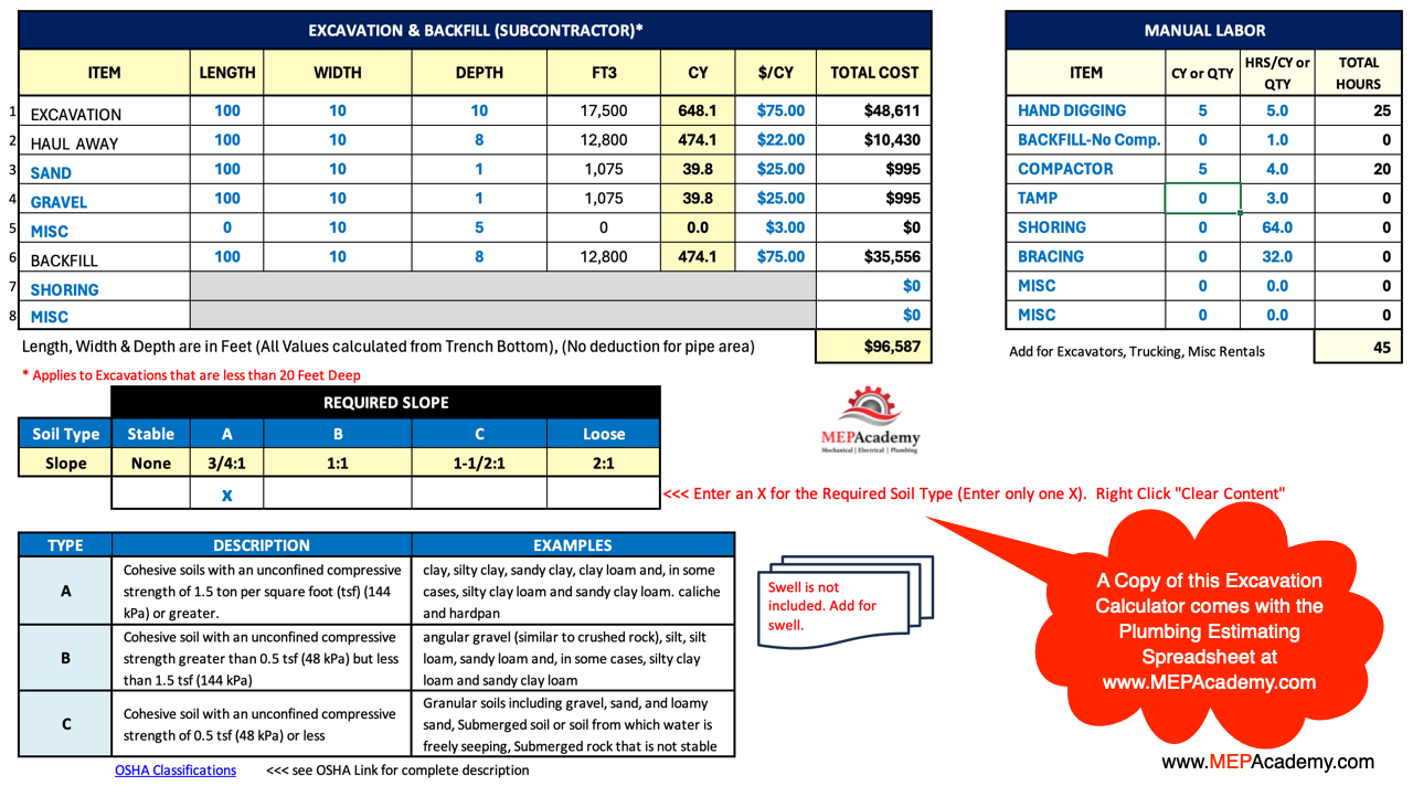
Using the Excavation calculator found in the MEP Academy Plumbing Estimating Spreadsheet you can easily calculate the required cubic yards required. Just enter the soil type along with the length, width and depth of the excavation or trench. The calculator takes into consideration the slope if indicated. Just put an “X” in the box for Stable Rock which doesn’t require a slope, or type A soil which is a 3/4:1 slope, type “B” at 1:1, and type “C” soil for 1-1/2:1. The total cubic yards are automatically calculated including any sloped area.
Soil Excavation Calculator in the MEPAcademy’s Plumbing Estimating Spreadsheet
To get a copy of the Estimating Spreadsheet with the Excavation and backfill calculator follow this link. Plumbing Estimating Spreadsheet.
Benching
Single and multiple benching are techniques used to create safe slopes in excavations, particularly in trenches and other large soil removals. These methods help prevent soil collapse and ensure worker safety by reducing the risk of cave-ins. Here’s a description of each:
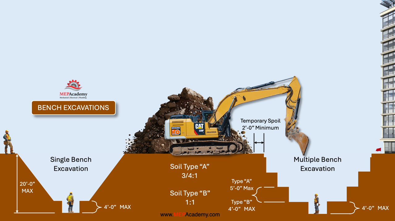
Bench Excavations
Single Bench
A singe bench involves excavating the soil to create one horizontal step or bench along the slope of the excavation. This bench provides a stable working platform and reduces the steepness of the slope, which helps prevent soil from sliding into the trench.
Single benching is typically used in less deep excavations where the height of the slope does not require multiple steps for stability. It’s suitable for soils that are relatively cohesive and stable.
Multiple Bench
A multiple bench cut involves creating a series of horizontal steps or benches at regular intervals along the slope of the excavation. Each bench acts as a break in the slope, significantly reducing the likelihood of a cave-in by supporting the soil above it.
Multiple benching is used in deeper excavations where a single bench would not provide sufficient stability. It is especially important in less cohesive soils that are more prone to collapse. This method ensures greater safety by distributing the weight of the soil and providing additional support.
Key Considerations
As a general rule, the bottom vertical height of the trench must not exceed 4 ft (1.2 m) for the first bench. Subsequent benches may have a vertical height of up to 5 ft (1.5 m) in Type A soil and 4 ft (1.2 m) in Type B soil, reaching a total trench depth of 20 ft (6.0 m).
Slopes vs Trenches
To avoid the need for a sloped excavation, which can be impractical in certain situations due to space constraints or other factors, several alternative protective systems can be used to ensure worker safety and prevent cave-ins. Trenches 5 feet (1.5 meters) deep or greater require a protective system unless the excavation is made entirely in stable rock. If less than 5 feet deep, a competent person may determine that a protective system is not required. The alternatives to sloping include these trench options:
1. Shoring Systems:
Hydraulic Shoring: Uses hydraulic pistons to apply pressure to trench walls, holding them in place. It’s adjustable and can be quickly installed and removed.
Mechanical Shoring: Involves using metal supports such as screw jacks, struts, and beams to brace trench walls. These systems are strong and can be tailored to the specific dimensions of the trench.
Pneumatic Shoring: Similar to hydraulic shoring but uses air pressure to stabilize the trench walls.
2. Trench Boxes
Trench boxes are robust steel or aluminum structures placed inside the trench to protect workers from cave-ins. They provide a safe working area within the trench and are particularly useful for deep or narrow trenches.
Trench boxes come in various sizes and configurations to suit different excavation needs and can be stacked for deeper excavations.
3. Shield Systems:
Shield systems are portable, protective structures that can be moved along the trench as work progresses. They can be made of steel, aluminum, or composite materials and offer flexibility in terms of size and strength.
Examples include slide rail systems, which provide support to the trench walls as the excavation proceeds.
We have shown you three protective system and there are many others available.
Using these protective systems allows for vertical or near-vertical trench walls, which can be critical in areas with limited space or where traditional sloping is not feasible. The choice of system depends on factors such as soil conditions, trench depth, available space, and project-specific requirements. Each method provides a safe working environment for workers and ensures compliance with OSHA regulations and industry safety standards.
When is Shoring Required
Shoring is required during excavation or trenching when the soil’s stability is compromised, posing a risk of collapse or cave-in. Here are common scenarios when shoring is necessary:
Unstable Soil Conditions
Shoring is essential when excavating in soil types prone to collapse, such as loose or granular soils (Type C soils according to OSHA classification). These soils lack cohesion and are at a higher risk of cave-ins without support.
Deep Excavations
As the depth of the excavation increases, the lateral pressure exerted by the surrounding soil also increases. Shoring becomes necessary to prevent the walls of the trench from collapsing inward under the pressure, ensuring the safety of workers.
Adjacent Structures
When excavating near existing structures, utilities, or roads, shoring may be required to prevent soil movement that could damage adjacent infrastructure. Shoring also provides stability to the excavation site, minimizing the risk of ground settlement or subsidence.
Water Table
Excavations conducted below the groundwater table are susceptible to water seepage and soil instability. Shoring is necessary to prevent water infiltration and maintain the integrity of the excavation walls, especially in cohesive soils that may become saturated and lose strength.
Changing Soil Conditions
Soil conditions can change unexpectedly during excavation due to weather conditions, groundwater fluctuations, or disturbances from nearby activities. If soil stability becomes compromised, shoring may be required to ensure the safety of workers and prevent accidents.
Regulatory Requirements
Local regulations and safety standards may dictate when shoring is required based on factors such as excavation depth, soil type, and proximity to existing structures or utilities. Compliance with these regulations is essential to ensure safe excavation practices.
In summary, shoring is necessary during excavation or trenching operations to provide support and stability to the excavation walls, reducing the risk of collapse and ensuring the safety of workers and surrounding infrastructure.
Soil Compaction
Compaction refers to the process of densifying the soil or backfill material to increase its load-bearing capacity and prevent settling or shifting over time. After plumbing pipes or structures are placed in the excavated trenches, the backfill material is added in layers and each layer is compacted using mechanical means such as vibratory plate compactors, rollers, or tampers. Proper compaction ensures that the soil is stable and that voids are minimized, which helps to protect the integrity of the plumbing infrastructure, preventing future issues such as pipe displacement or leaks due to ground movement.
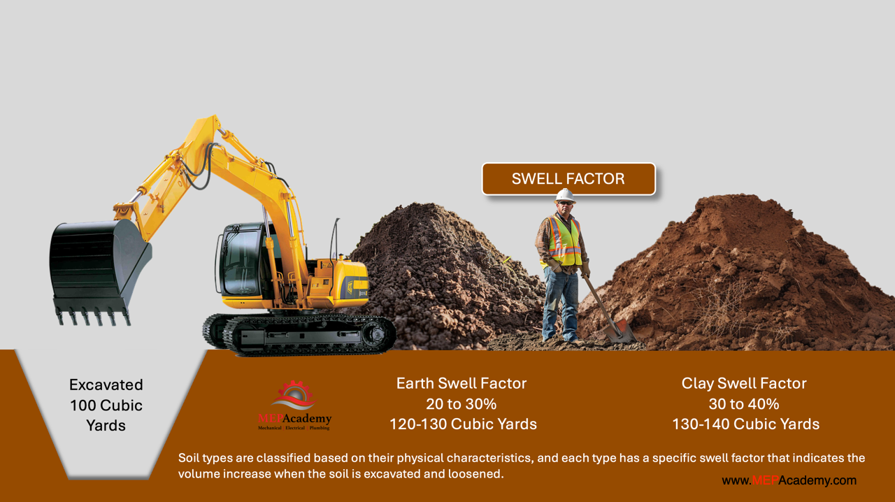
Swell Factor
Swell refers to the increase in volume that soil or excavated material undergoes when it is disturbed and removed from its natural, compacted state. When soil is excavated, it expands because the tightly packed particles are loosened, resulting in an increase in volume. This phenomenon is known as swell.
Soil Swell Factors. When soil increases in size after excavation.
Understanding swell is important for plumbers and construction professionals because it affects the amount of backfill material that will be required to refill an excavated trench or hole. Proper planning for swell ensures that there is sufficient material to achieve the desired compaction and stability when backfilling around plumbing installations.
Sand and Gravel Bedding
Using sand and gravel at the bottom of an excavation where piping is being installed serves several important purposes:
Providing a Stable Bedding:
Sand and gravel create a stable and even bedding for the pipes, ensuring that they are well-supported along their length. This reduces the risk of pipe deflection or damage due to uneven settlement or point loading.
Facilitating Drainage:
Sand and gravel promote good drainage around the pipes, preventing water accumulation that could lead to soil instability or erosion. Proper drainage helps maintain the integrity of the piping system and prevents issues related to waterlogging or frost heave.
Protecting Pipes from Sharp Objects:
Sand and gravel act as a cushion, protecting the pipes from sharp rocks or other debris in the soil that could puncture or damage them. This is particularly important for plastic or PVC pipes, which are more susceptible to damage from sharp objects.
Easing Piping Installation:
The granular nature of sand and gravel makes it easier to achieve precise grading and alignment of the pipes during installation. This ensures that the pipes are laid at the correct slope and elevation for optimal performance.
Amount of Sand and Gravel Used
The amount of sand and gravel used at the bottom of an excavation varies depending on the type and size of the piping, as well as the project specifications. However, typical guidelines include:
Bedding Layer:
A bedding layer of sand or gravel is usually placed 4 to 6 inches (10 to 15 centimeters) thick. This layer provides a firm foundation for the pipes.
Initial Backfill:
After the pipes are laid, an initial backfill of sand or gravel is placed around and over the pipes to a depth of about 6 to 12 inches (15 to 30 centimeters) above the pipe. This initial backfill helps to secure the pipes in place and provides additional protection.
Final Backfill:
The final backfill, which may consist of the excavated soil or other suitable material, is then placed on top of the initial backfill. The final backfill is typically compacted in layers to prevent settling and ensure stability.
These layers help ensure that the pipes are properly supported, protected, and aligned, contributing to the longevity and functionality of the piping system. The exact specifications may vary based on local codes, engineering requirements, and the specific conditions of the project site.
Digging Equipment used for Excavations and Trenches
Excavations and trenches require specialized equipment to efficiently and safely remove soil and create the desired shapes and depths. Here are various types of digging equipment commonly used for these purposes:
Excavators
Excavators are versatile machines equipped with a bucket attached to a hydraulic arm. They can rotate 360 degrees and are capable of digging, lifting, and loading materials.
Excavators are suitable for a wide range of excavation tasks, including digging trenches, foundations, and utility trenches.
Backhoe Loaders
Backhoe loaders combine a backhoe (rear-mounted digging arm) with a loader (front-mounted scoop). They are versatile and commonly used in construction projects.
Backhoe loaders are useful for smaller excavation jobs, such as digging trenches for utilities, backfilling, and loading materials.
Trenchers
Trenchers are specialized machines designed specifically for digging narrow and deep trenches. They feature a rotating chain or blade that cuts into the ground to create the trench.
Trenchers are ideal for excavating trenches for utilities like water pipes, sewer lines, and electrical conduits.
Mini Excavators
Mini excavators are compact versions of standard excavators, with a smaller footprint and reduced weight. They offer increased maneuverability and are suitable for tight spaces.
Mini excavators are commonly used for small-scale excavation projects, landscaping, and utility installation in urban areas or confined spaces.
Crawler Excavators
Crawler excavators are equipped with tracks for stability and mobility over rough terrain. They offer high digging power and are suitable for heavy-duty excavation work.
Crawler excavators are used in large-scale excavation projects, such as road construction, mining, and earthmoving.
Skid Steer Loaders
Skid steer loaders are compact, maneuverable machines with a small turning radius. They feature a bucket or attachment mounted on a pivoting frame.
Skid steer loaders are versatile and can be used for various tasks, including excavation, loading, grading, and landscaping.
These are just a few examples of the equipment used for excavations and trenches. The choice of equipment depends on factors such as the size of the project, the type of soil, accessibility, and the specific requirements of the task at hand.
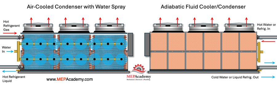
We’ll discuss an adiabatic fluid cooler, an air-cooled condenser with water spray, and an air-cooled condenser using adiabatic cooling.
Air-Cooled Condenser with Water Spray and Adiabatic Fluid Coolers
An adiabatic fluid cooler is a device used for cooling fluids, typically water or a water-glycol mixture, while an adiabatic air-cooled condenser is used to cool a refrigerant based systems. These systems are used in industrial and commercial applications. They operate based on the principle of evaporative cooling combined with a heat exchanger.
If you prefer to watch the video of this presentation, then scroll to the bottom.
How Adiabatic Cooling Works:
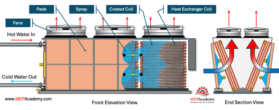
The hot water in an adiabatic fluid cooler flows into the heat exchanger. The heat exchanger consists of coils of tubes surrounded by fins. These tubes are in contact with the hot water. As the hot water flows through them, heat is transferred to the coil surface and fins of the heat exchanger. The heat exchanger can be provided with an epoxy coating to increase corrosion resistance without sacrificing unit capacity.
Adiabatic Fluid Cooler
Water is sprayed or circulated over a pre-cooling pad, to keep it fully wet. This fully wetted medium sits in front of the heat exchanger, and is often made of corrugated cellulose, synthetic material, or fibrous pad. Cool, dry ambient air is drawn through the wetted medium by a fan located on top of the unit, the air becomes humidified as some of the water evaporates into the air, absorbing heat from the surrounding air in the process.
The evaporation of water from the wetted medium extracts heat from the surrounding air, reducing the ambient dry bulb temperature within proximity to the wet bulb temperature. This cooled air then passes over the surface of the heat exchanger where it absorbs heat from the hot fluid inside the tubes and on the surface of the fins. The heat is then discharged to the atmosphere by fans sitting at the top of the unit. As a result, the hot fluid inside the tubes loses heat to the cooled air through the heat exchanger.
The cooled fluid exits the adiabatic fluid cooler and can be recirculated back into the system it’s cooling, such as an HVAC system or industrial process. This effectively transfers the absorbed heat to the adiabatic fluid cooler and then to the atmosphere.
Variable Speed Fans
The variable speed fans inside the adiabatic fluid cooler draws air through the wetted medium and across the heat exchanger to facilitate the cooling process. The speed of the fan(s) can be adjusted to control the cooling capacity of the unit.
By combining evaporative cooling with a traditional heat exchanger, adiabatic fluid coolers can achieve significant energy savings compared to conventional air-cooled heat exchangers, especially in hot and dry climates where evaporative cooling is particularly effective.
Reduces Water Consumption
The Adiabatic fluid cooler can eliminate or significantly reduce water consumption compared to the traditional evaporative systems. They can be operated without water until ambient conditions require additional capacity to meet demand. This reduces water consumption and the cost to treat and dispose of water. There is no water basin to hold water or that can gather dirt and debris. This is because the water passes through once and isn’t recirculated so there is no need for a recirculation pump.
Adiabatic Condenser
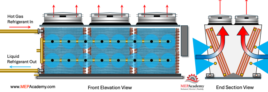
The adiabatic version of the air-cooled condenser uses a fully wetted medium that sits in front of the heat exchanger coil. The air flow and heat transfer process is the same as previously discussed using the adiabatic fluid cooler for water, except now it’s refrigerant as the medium.
Air-Cooled Condenser with Water Spray
For the air-cooled condenser, the refrigerant vapor enters the condenser and leaves as high-side refrigerant liquid. The system will turn on the water spray when it fails to maintain the refrigerant condensing pressure.
Refrigerant Condenser Cooled by a Water Spray System
The water is sprayed outward away from the coil into the air stream. The air is pulled across the coil by the variable speed fans. The heat from the hot refrigerant is transferred to this cooler air causing the refrigerant to condense into liquid. The condenser will conserve water by running dry and only spraying water when ambient conditions require a lower entering temperature. That’s why these systems are recommended for high ambient dry bulb climates or high temperature applications.
What is adiabatic Cooling?
Adiabatic fluid coolers or condensers operate like dry cooling systems, except they have water running over pre-cooling pads. The air is drawn through the pads depressing the ambient dry bulb temperature of the incoming air. The depressed or reduced dry bulb temperature provides for greater system heat rejection than a dry system.
HVAC School for Technicians. In this article we’ll cover what you can expect to be paid as an Air Conditioning and Refrigeration Technician, the education required, and what you can be expected to do while at work.
If you prefer to watch the Video of this presentation, then scroll to the bottom.
Air Conditioning and Heating systems play a crucial role in controlling the temperature, humidity, and air quality within residential, commercial, and industrial buildings. Essential items such as food and medicine rely on refrigeration to prevent spoiling. Skilled technicians are responsible for the repair, maintenance, and installation of heating, air conditioning, and refrigeration systems.
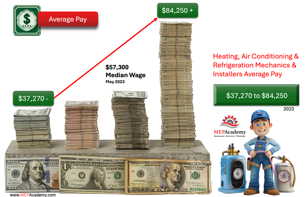
Average Pay for a HVACR Technician
How much money can you make as an Air Conditioning and Refrigeration Technician?
Air Conditioning and Refrigeration Technicians get paid anywhere from $37,270 and less for the bottom 10% of workers, to more than $84,250 per year for the top 10% of earners according to the Bureau of Labor Statistics for 2023. The median wage was $57,300 in May 2023.
The Average Pay for an HVACR Technician for the year 2023
Most of the HVACR technicians work at full time positions, which may require evening and weekend hours. During peak seasons for heating or cooling, HVACR technicians can be requested to work overtime or irregular hours to help customer get their systems up and running after they breakdown. Obviously working overtime will increase your hourly pay.
Current Job Opportunities
According to the Bureau of Labor Statistics, the Employment of heating, air conditioning, and refrigeration mechanics and installers is projected to grow 6 percent from 2022 to 2032, faster than the average for all occupations.
About 37,700 openings for heating, air conditioning, and refrigeration mechanics and installers are projected each year, on average, over the decade. Many of those openings are expected to result from the need to replace workers who transfer to different occupations or exit the labor force, such as to retire.
EDUCATION
While a high school diploma or equivalent may be the minimum requirement for many entry-level positions, obtaining formal education through a vocational school, community college, or technical institute can provide a solid foundation. Some of these vocational programs even take individuals lacking a high school diploma. Look for programs specifically focused on HVAC (heating, ventilation, and air conditioning) or refrigeration technology.
Training Programs
Consider enrolling in an apprenticeship or training program offered by trade associations, Unions, Technical Schools, or HVAC companies. These programs often combine classroom instruction with hands-on experience under the guidance of experienced technicians. If accepted into a Union apprenticeship program you’ll be paid while learning.
HVAC Service Technician fixing a Fan
Certification
Although not always mandatory, obtaining certification can enhance your credibility and job prospects. A Certificate of Achievement can be secured from an HVACR technical school in 2 years or less. This can shorten the period from entering school to getting a full-time job. After your first semester in a technical school, you could seek a part-time apprenticeship job with a local HVAC contractor.
The most widely recognized certification for HVAC technicians in the United States is offered by North American Technician Excellence (NATE). Other certifications may be available depending on your location and specialization.
Licensing
In some jurisdictions, HVAC technicians are required to obtain a license to work independently. This won’t stop you from working for others. Requirements vary by state or country, so be sure to research the specific licensing regulations in your area. States like California requires a contractor’s license to open your own company and require prior work experience.
Skills Development
Develop a strong understanding of heating, ventilation, air conditioning, and refrigeration systems, as well as electrical and mechanical principles. Good problem-solving skills, attention to detail, and the ability to work independently are also important.
Experience
Gain practical experience by working as an apprentice or entry-level technician under the supervision of experienced professionals. This will allow you to apply theoretical knowledge in real-world settings and develop valuable troubleshooting skills.
Continuing Education
Stay updated on advances in HVAC technology and industry regulations through continuing education courses, workshops, and seminars. This will ensure that your skills remain relevant and competitive in the field.
By following these steps and continually honing your skills, you can become a competent and successful HVACR technician.
The Work of an Air Conditioning & Refrigeration Technician
Air conditioning and refrigeration technicians, install, maintain, and repair, heating, ventilation, air conditioning, and refrigeration systems. These systems are found in residential, commercial, and industrial buildings.
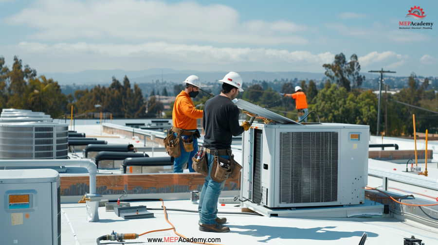
HVAC Technicians working on Rooftop HVAC Units
This could include work on small residential systems such as split systems or packaged units. Also large chilled water plant equipment such as air-cooled and water-cooled chillers. Chillers provide cold water that gets pumped throughout the building. Or you could be working on commercial boilers that provide heating. There are various additional commercial systems that add an extra layer of complexity to the job.
Their responsibilities typically include:
Installation
Installing new HVACR systems, including air conditioners, furnaces, heat pumps, Variable Refrigerant Flow Systems, refrigeration units, and ventilation systems. Installing these systems in accordance to specifications and building codes.
Installation of new HVAC Units
This includes learning how to cut and prepare copper tubing ends, including flaring, swaging, and brazing.
Maintenance
Performing routine maintenance tasks such as cleaning coils, replacing filters, checking refrigerant levels, lubricating moving parts, and inspecting electrical connections. This ensures systems operate efficiently and safely.
Repair
Diagnosing and troubleshooting problems with HVACR systems, including issues with components such as compressors, motors, thermostats, boilers, and pumps. This includes making the necessary repairs to restore functionality.
Refrigerant Handling
Handling refrigerants safely and in compliance with environmental regulations, including recovering, recycling, and disposing of refrigerants according to industry standards.
Customer Service
Interacting with customers to understand their heating and cooling needs. Providing recommendations for system upgrades or replacements. Ensuring customer satisfaction with the quality of service provided.
Safety Compliance
Adhering to safety protocols and regulations to minimize risks of injury or property damage during installation, maintenance, and repair activities.
Overall, air conditioning and refrigeration technicians play a crucial role in maintaining comfortable and efficient indoor environments, by ensuring that HVACR systems operate effectively and reliably.
Where HVACR Technicians Work
Air conditioning and refrigeration technicians work in a variety of environments, depending on the specific job and industry. Here are some common work environments for HVACR technicians:
Residential Settings
Technicians may work in homes, apartments, and condominiums to install, repair, and maintain heating, ventilation, air conditioning, and refrigeration systems for individual homeowners or property management companies.
Commercial Buildings
HVACR technicians often work in commercial settings such as office buildings, retail stores, restaurants, and hotels. They may install and service larger HVACR systems to provide climate control for occupants and ensure comfort and productivity.
Industrial Facilities
In industrial settings such as factories, warehouses, and manufacturing plants, technicians may install and maintain specialized HVACR systems to regulate temperature and humidity levels for equipment operation and product storage.
Healthcare Facilities
Hospitals, clinics, and medical laboratories require precise temperature and humidity control to maintain a sterile environment and protect sensitive medical equipment. HVACR technicians may work in these facilities to install and service specialized HVACR systems.
Educational Institutions
Schools, colleges, and universities rely on HVACR systems to create comfortable learning environments for students and faculty. Technicians may be employed by educational institutions or contracted to provide HVACR services.
Government Buildings
HVACR technicians may work in government buildings such as courthouses, libraries, and municipal offices to maintain climate control systems and ensure the comfort and safety of employees and visitors.
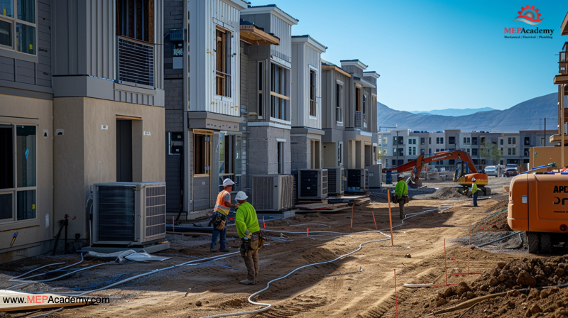
Construction Sites
During new construction or renovation projects, HVACR technicians may work on construction sites to install piping. This includes installing HVACR equipment according to building plans and specifications.
Outdoors
Some tasks, such as HVACR system inspections, maintenance, and repairs, may require technicians to work outdoors, especially when servicing rooftop units or equipment located in outdoor enclosures.
Overall, air conditioning and refrigeration technicians can expect to work in a variety of indoor and outdoor environments. They will encounter different conditions and challenges depending on the specific job and industry. They must be prepared to adapt to different work settings and follow safety protocols. This is to ensure their well-being, and the efficient operation of HVACR systems.