How many CFM per Ton should you consider for an HVAC unit? How is CFM per Ton figured? Have you ever heard of anyone throwing around CFM per Ton numbers like 400 CFM per Ton? What do these numbers really mean? Is it better to have more or less CFM per Ton? We’ll cover the conditions that impact CFM per Ton on various air conditioning performance charts and how you can determine the CFM per Ton.
Affects of Outside Ambient Temperature on Capacity
We’ll first look at the Outdoor Ambient Temperature and how it effects the capacity of a 6-ton split system air conditioner. Here we have a chart for the 6-ton air conditioner with the 95 F highlighted in pink, and the AHRI dry bulb temperature of 80 F highlighted in blue under each outdoor temperature, and the AHRI wet bulb temperature of 67 F and the intersecting columns and rows for these temperatures.
We show the CFM settings for this chart at 2400 which corresponds to 400 CFM per Nominal Ton. The 2400 CFM row represents 400 CFM per Ton as follows 6 Tons x 400 CFM/Ton = 2,400 CFM.
- TC = Total Capacity in MBH
- MBH = btu’s in 1000’s
- SHC = Sensible Heat Capacity
If we follow the 2400 cfm row at 67 F wet bulb temperature, you’ll notice that the total capacity keeps decreasing as the outdoor ambient temperature gets warmer. For instance, at 85 F ambient the AC unit provides 74.1 MBH of cooling, and at 105 F ambient the total capacity drops to 67.7 MBH.
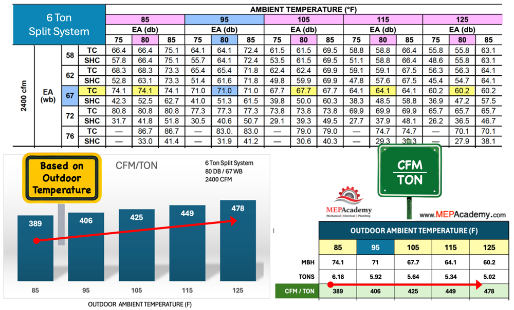
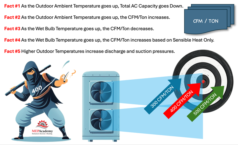
Fact #1 As the Outdoor Ambient Temperature goes up, Total AC Capacity goes Down.
Affects of Outside Air Temp on CFM per Ton
If we plot these values on a chart, we can see how CFM/Ton changes with the Outside Ambient Temperature. With the air conditioner providing a constant air volume of 2400 CFM and the Capacity decreasing as the Outdoor Ambient Increases, this implies that the same amount of CFM is provided for less capacity (Tons) at higher outdoor temperatures, hence the AC unit goes from 389 CFM/Ton to 478 CFM/Ton.
So, is more CFM/Ton a good thing? In this case no, as it reflects that more air is required to be delivered for every ton of air conditioning. This is due to the air conditioner having to work harder at the elevated temperature. Most Air Conditioners are derated in capacity when the outdoor air temperature exceeds 95 F.
Fact #2 As the Outdoor Ambient Temperature goes up, the CFM/Ton increases.
Affects of Wet Bulb Temperature on CFM per Ton
When the indoor wet bulb temperature increases, the CFM per ton of an air conditioning system typically decreases. As the indoor wet bulb temperature rises, the system may need to increase its airflow rate (CFM) to maintain the desired indoor temperature and humidity levels.
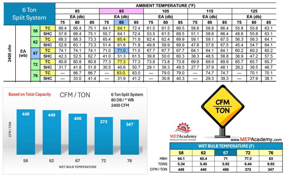
Fact #3 As the Wet Bulb Temperature goes up, the CFM/Ton decreases.
CFM per Ton using Sensible Heat Only
There are two ways to look at CFM/Ton, one is based on total load, the other based on sensible heat. The system’s sensible heat ratio (SHR) represents the ratio of sensible cooling (temperature reduction) to total cooling (temperature and humidity reduction). Another is sensible heat capacity (SHC) as shown on this chart, which represents the BTU/hr. capacity of the system at the stated conditions. Let’s look at the effect on sensible capacity when the indoor wet bulb temperature changes.
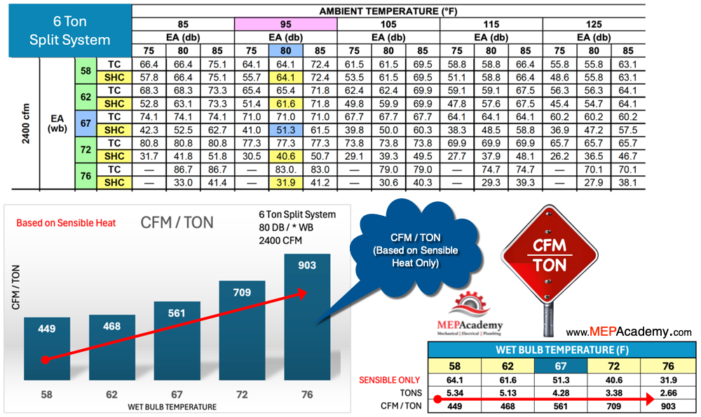
A lower SHC means that a greater portion of the cooling capacity is dedicated to removing moisture from the air rather than reducing its temperature. We can see by this performance chart, that as the indoor wet bulb temperature increases the sensible capacity decreases.
This means that based on our 2400 cfm and the sensible capacity only, our CFM/Ton increases as the wet bulb temperatures increases. This is the exact opposite of the results we get from CFM versus total capacity. Because the system uses more of its capacity for removing moisture there is less left over to remove sensible heat. This is why it’s important to understand the latent heat load generated within a room or brought in for ventilation air or by infiltration.
Fact #4 As the Wet Bulb Temperature goes up, the CFM/Ton increases based on Sensible Heat Only.
Reading Air Conditioning Performance Charts
Here is a different manufacturers performance data for their 6-ton air conditioner. As we already learned in the previous examples, as the outdoor air temperature increases the system capacity decreases. Notice also as the outdoor temperature increases the high side pressure increases from a low of 275 to 527 psi. Also note that the higher the moisture content or the wet bulb temperature the greater the system pressure. The hotter it gets outside the higher the system pressure. As the high side pressure goes up, the low side pressure follows.
Fact #5 Higher Outdoor Temperatures increase discharge and suction pressures.
400 CFM per Ton Rule of Thumb
The “400 CFM per ton” rule of thumb is a commonly used guideline in the HVAC industry to estimate the airflow requirements for air conditioning systems. It suggests that for every ton of cooling capacity provided by the air conditioner, approximately 400 cubic feet per minute (CFM) of airflow should be delivered to the conditioned space.
This rule of thumb is based on a combination of engineering principles, empirical data, and practical experience in the design and operation of air conditioning systems. While it is widely used as a general guideline for estimating airflow requirements, it is important to note that actual airflow needs may vary depending on factors such as climate conditions, building characteristics, equipment efficiency, and occupant comfort preferences.
The 400 CFM per ton rule of thumb is intended to provide a starting point for HVAC designers and engineers to estimate airflow requirements during system design and sizing. However, it is not a substitute for detailed engineering analysis and calculation. It should be used with caution, taking into account the specific requirements and constraints of each project.
CFM per Ton Calculation Methods
CFM per ton can be based on total BTUH (British Thermal Units per hour) capacity or sensible heat capacity only. This depends on the specific application and design requirements of the air conditioning system.
Total BTUH Capacity
When CFM per ton is based on total BTUH capacity, it accounts for both sensible heat and latent heat removal. This means that the airflow rate (CFM) is calculated to meet the combined cooling load of the space, including both sensible cooling (temperature reduction) and latent cooling (humidity removal). In this case, the airflow rate is typically higher to accommodate the additional energy required for dehumidification.
Sensible Heat Only
Alternatively, CFM per ton can be based on sensible heat capacity only. This approach is commonly used in applications where humidity control is not a primary concern. In these cases, the airflow rate may be lower since it only needs to meet the sensible cooling requirements of the space.
In practice, the choice between total BTUH capacity and sensible heat capacity for calculating CFM per ton depends on factors such as climate conditions, building occupancy, humidity levels, and comfort requirements. HVAC designers and engineers evaluate these factors to determine the most appropriate airflow rate for achieving optimal comfort and energy efficiency in the conditioned space.