How do Geothermal Heat Pumps work? We’ll learn the different types of Geothermal Heat Pump Systems, along with information on where to find incentives and rebates, the efficiency compared to a regular heat pump and the cost you might expect to pay to have one installed.
If you prefer to watch the video version of this presentation than scroll to the bottom or click the link here “How do Geothermal Heat Pumps work?“
The use of geothermal heat pump systems takes advantage of the earths relatively constant temperature beneath the surface based on location and height. The earth maintains a ground temperature range from 45°F (7°C) to 75°F (21°C). taking advantage of this natural heat source is what gives the Geothermal Heat Pump greater efficiencies than a standard heat pump. This source of heat is also naturally renewable making it a great energy source.
The Geothermal Heat Pump System comes with various options on how to tap into this natural reservoir of heat. We will discuss open and closed loop systems, and horizontal versus vertical system, and when to use them.
Checkout these Geothermal Heat Pump hereThe cost of a geothermal heat pump system is more than that of a typical heat pump system, but this cost is saved by possible incentives and rebates in addition to the yearly energy savings which we’ll cover shortly.
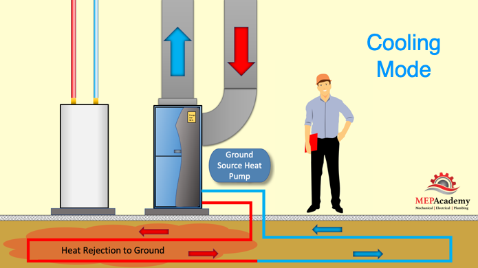
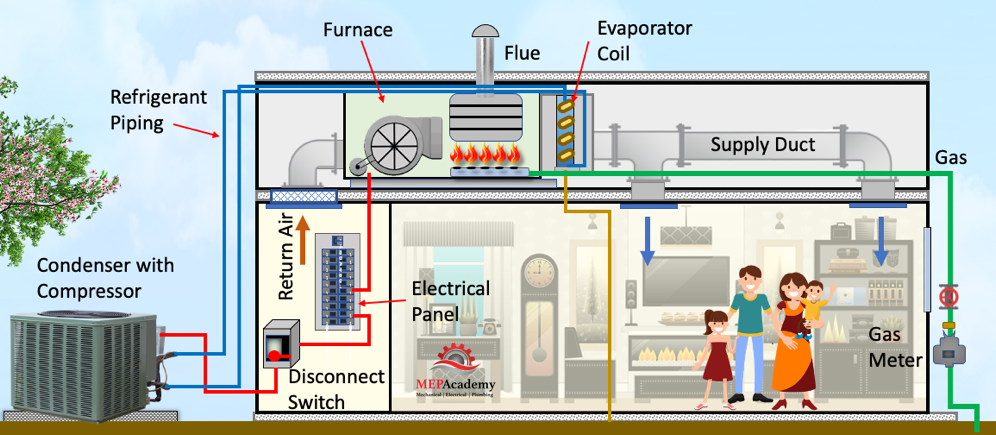
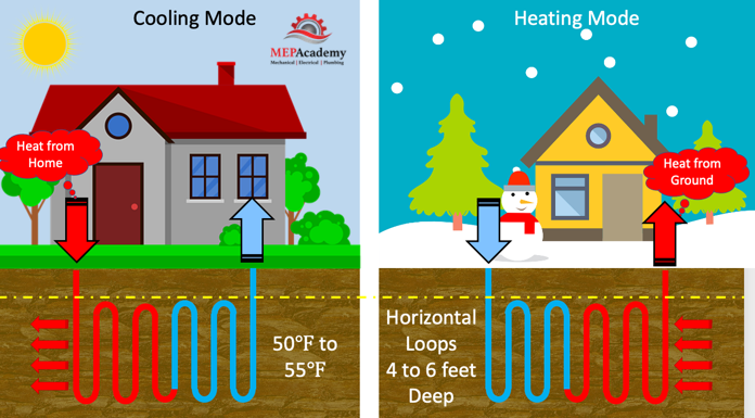
Geothermal Heat Pump in Cooling mode
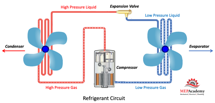
In cooling mode, warm air from within the building is brought into the ground source heat pump. The heat pumps indoor coil will absorb the warm air into the cooler liquid refrigerant circulating through the coil. Absorbing the heat will cause the refrigerant to boil and turn into a gas. The refrigerant will circulate through the system and be absorbed by the cooler water circulating through the system from the underground.
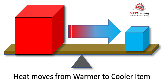
The heat is then absorbed by the water and circulated underground where the heat is rejected to the cooler ground. Remember the 2nd law of thermodynamics states that heat moves from a warmer to a cooler item. The water and refrigerant never come in contact with each other. For a complete understanding of the refrigerant cycle see our other video.
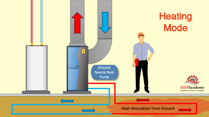
Geothermal Heat Pump in Heating mode
In heating mode the opposite occurs. We will always follow the heat as stated by the second law of thermodynamics. The heat in this case is provided by the ground. The cool water is circulated to the ground where it absorbs heat from the ground.
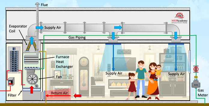
This warm water then circulates into the ground source heat pump where it is absorbed into the refrigerant causing the liquid refrigerant to boil and turn into a vapor. The hot refrigerant is then circulated to the indoor coil where it comes in contact with the cooler return air from the space. The cool return air absorbs the heat from the hot refrigerant and heats the leaving supply air.
Checkout these Geothermal Heat Pump hereTypes of Geothermal Heat Pump Systems
In order to tap into the earths free source of energy we’ll need to run plastic tubing beneath the surface. This tubing acts as a heat exchanger between the fluid in the tubes and the ground. The tubing is configured in various patterns and depths based on available land area and the composition of the soil below ground.
If there is enough ground area and the soil is good for heat transfer than a horizontal system can be installed. If there isn’t enough ground area or the soil isn’t good for heat transfer, then vertical tubing is another option. These systems circulate water with antifreeze or there is the option to use a refrigerant based system. Another option if you have a body of water nearby is to use an open or closed loop system into the body of water. We’ll cover each of these now.
Horizontal loop GSHP
Given enough area for the tubing to achieve the heat transfer required to support the cooling and heating load of the building or home, using the horizontal loop is more feasible than drilling vertically. Horizontal loops are buried from 3 to 5 feet (0.9 to 1.5m) deep and are economically feasible as long as excavation can be done without difficulty due to soil composition.
The length of the loop is determined by the amount of heat transferred required or the tonnage of the heat pump. In order to determine the length of tubing required, a heating and cooling load calculation is performed on the building. Tube length can run between 500 to 600 feet (152 to 182m) per ton of heat pump capacity. This means that a 4-ton system would require 2,000 to 2,400 feet (610 to 732m) of tubing. Allowing for spacing to achieve efficient heat transfer, an approximate area from 1/4 to 3/4 acre could be required for a typical sized home.
Vertical Loop GSHP
Using vertical loops requires less land area as the tubing is sent hundreds of feet below the surface. For commercial buildings this could include bore holes 100 to 500 feet (30 to 152m) deep, spaced 20 feet (6m) apart to allow for proper heat transfer. These holes can be up to 4” to 6” (10 to 15cm) in diameter and contain plastic tubing that traverses to the bottom where it makes a U-turn and comes back out of the hole where it connects to a horizontal manifold. Residential systems would require fewer bores and would most likely be 300 feet (91m) deep or less. Vertical loops can be used when there isn’t enough land area and when greater efficiency maybe required.
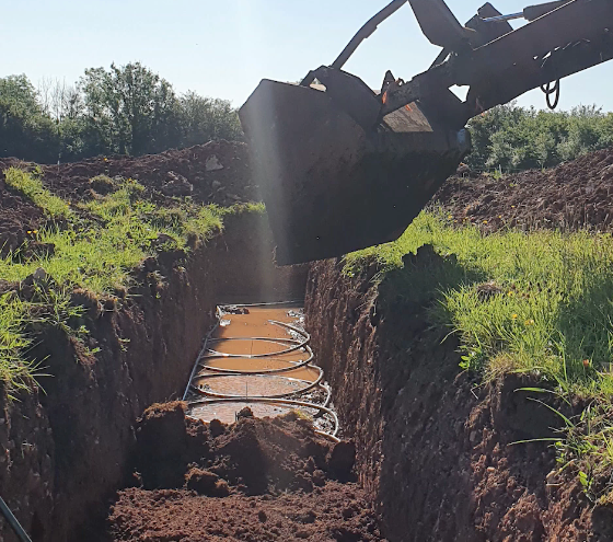
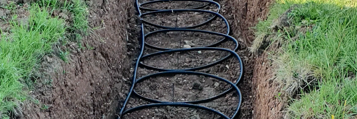
The Slinky Geothermal Loop Installation
This geothermal System uses coiled tubing which allows for the use of less area by increasing the heat transfer ability per area used. This occurs because the tubing is coiled in the trench requiring less land area, but more tubing per linear feet. The coils are laid in a horizontal trench 3 to 8 feet (1 to 2.4M) deep. A combination of water and antifreeze circulate through the tubing and the heat pumps heat exchanger.
DX Refrigerant Based Geothermal Ground Loop
Another energy efficient option is the DX ground loop system that uses refrigerant circulating around a buried copper coil. Instead of water, refrigerant is the heat transfer medium, avoiding the additional step of transferring the heat to the refrigerant in a water based system. This helps with the increased efficiency and greater heating capacities. This also eliminates the need for a water pump, as this is a waterless system.
Another difference is that this loop is in a wide vertical hole, something like 3 feet (1m) in diameter and 70 feet (21m) deep. This eliminates the need for large areas of land. The soil will need to be tested to make sure it’s not corrosive to the copper, and if found to be corrosive then a ground loop protection method will be installed.
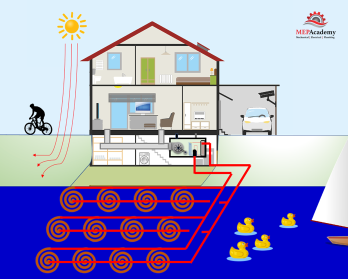
Checkout these Geothermal Heat Pump herePonds, Lakes or Water Based Sources
Having a body of water near the property allows for the option of using water as the heat sink, where heat is transferred to and from the tubing either in an open or closed loop arrangement.
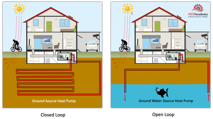
Closed loop Systems.
The tubing can be installed at the bottom of a pond on the property if the pond is large enough, maybe 1/2 an acre or larger depending on its depth. If close enough to a lake this option is also available pending local authority approval. A pump circulates the water and antifreeze solution through tubing within the body of water where it rejects or absorbs heat from the geothermal heat pump.
Open Loop System
The difference between the closed and open loop systems is that the open system uses the pond, well or lake water to be circulated through the tubing and up to the heat pump. This raises additional concerns for environmentalist and code authorities about water depletion and ground water contamination.
The use of well water is an option if a body of water exist under your property and the use of a horizontal ground loop doesn’t work for lack of area or feasibility. Open loop systems require more maintenance than a closed loop, due to the minerals and other impurities that maybe in the water.
Are open loop Systems Legal?
There are laws governing the use of bodies of water for the use of any open system that will take water from the source and use it in some process before returning it back again. The legitimate concern is what happens to the quality of the water in the process. Another concern is for the wild life or living organism in the water that maybe effected by the warmer discharge temperatures.
You’ll need to check with the jurisdictional authority when contemplating the use of any body of water. An alternative would be a closed loop system which should be less stringent.
Is a Geothermal Heat Pump System worth the Cost?
Energy savings from the installation of a geothermal heat pump system could take anywhere from 5 to 10 years to payback the additional investment cost above a conventional system according to the department of energy.
The DOE states that an average geothermal heat pump system costs about $2,500 per ton of capacity. If a home requires a 3-ton unit, then it would cost about $7,500 (plus installation and drilling costs). A comparable Air Source Heat Pump system with air conditioning would cost about $4,000, but the energy costs could easily equate to the extra cost of installing a geothermal heat pump.
Geothermal heat pump systems have an average 20+ year life expectancy for the heat pump itself and 25 to 50 years for the underground infrastructure.
Geothermal Heat Pump System Frequently Asked Questions (FAQ)
1) How Long Do Geothermal Loops Last?
The geothermal loop is buried underground so it’s protected well and should last anywhere from 50 to 100 years. The underground piping often has a warranty period of 25 to 50 years, check with the manufacture about their warranty period.
2) How long does it take for a Geothermal System to Pay For Itself?
Based on the type and size of the project the payback period varies but expect 4 years or more. Ask your contractor for a payback analysis.
3) Do Geothermal Systems use a lot of Energy?
No. Geothermal systems are used for the purpose of saving energy and providing a more sustainable solution. The heat pump uses electricity but more efficiently.
4) Do Geothermal System Require A lot of Maintenance?
No. Geothermal systems require less maintenance than other types of heat pumps.
5) How Deep Should Geothermal Horizontal Loops be?
Anywhere from 3 to 8 feet (1 to 2.4m) deep is a common depth for a horizontal geothermal heat pump system. The tubing can be placed side by side in a couple feet wide trench, or spaced several feet apart at different depths in a more shallow trench.
6) What is better, a Closed or open loop Geothermal System?
A open loop system will be more efficient and less costly, but will be more regulated due to the system discharging into the water way.
7) Can I Install my Own Geothermal System?
The installation is best done by an experienced contractor and is not something a home owner should attempt on their own.
8) Do you need supplemental Heat when using a Geothermal Heat Pump?
A properly sized Geothermal heat Pump should be sufficient to handle the calculated heating and cooling load of a space. This is why it’s important that a load calculation be done to ensure that the system is sized correctly. If need be, additional electric heat can come on after its maxed its capacity
9) Is a Geothermal System worth the investment cost?
One of the greatest benefits of a geothermal system is that they use 25 % to 50% less electricity than your typical heating and cooling system. And efficiencies can be increased by adding a desuperheater that heats the domestic water. If you consider the environment then the investment value is increased as less carbon is injected into the environment.
10) What material is used for geothermal heat pump underground tubing?
The three most commonly used materials for water based systems include PEX (polyethylene), HDPE (high-density polyethylene) and PE-RT (polyethylene (PE) resin).
11) Can my Geothermal Heat Pump be powered by a Solar System?
A PV Solar system can provide the power needed to run a geothermal heat pump. Have your contractor do a comparative analysis between the capacity of the solar system and the required power of the heat pump system.
12) How much does a Geothermal System Cost?
Cost vary by location and type of system installed. Residential systems can range from $25,000 on the low end for a small system to over $60,000 for larger systems. For commercial properties the range is much greater because the system sizes encountered are much larger than residential systems.
13) What size tubing is used for Geothermal Heat Pump Systems?
The loops are typically using 3/4” to 1” (1.9 to 2.54cm) tubing, while the main headers will be larger in the range of 1-1/2” (3.8cm) for a 3-ton system.
14) Are there any Tax Rebates or Incentives for Geothermal Heat Pump Systems?
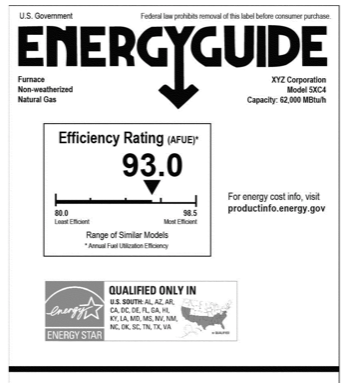
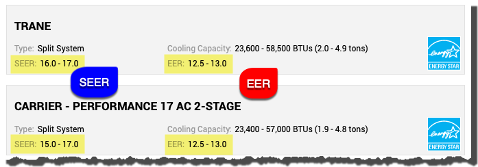
In 2022 tax credits were extended through 2034 for ENERGY STAR rated geothermal systems. Check local utility companies for incentives and geothermal Heat Pump manufactures for rebates.
Geothermal Heat Pump Process
One of the first things when considering the installation of a geothermal heat Pump system is to engage an experienced contractor. The contractor should develop a plan for the execution of the system starting with the options on the type of Geothermal System appropriate for your site. This should include a site visit from the contractor and a review of the home or space. A heating and cooling load will need to be done on the home to determine the correct size of the system.
Included in the contractors review should be an analysis of the energy savings from the various heat pump systems, including any possible rebates, incentives or tax credits.