We’ll cover How HVAC Heat Pumps Work, and the differences between an Air-Cooled and Water-Cooled Heat Pumps. We’ll explain the different styles of heat pumps used in residential and commercial buildings. You’ll learn the differences between air and water-cooled, packaged versus split systems, vertical versus horizontal, and ground and water source heat pumps.
If you prefer to watch the YouTube version of this presentation scroll to the bottom.
Refrigerant Cycle of a Heat Pump System – Reversing Valve
The Heat Pump has the same basic refrigeration circuit as a standard Air Conditioner except for a few specific components to help it succeed in both heating and cooling with the same refrigerant circuit. See our video on Refrigerant Circuits if you need a basic understanding on how they work. The main component that helps it function in both modes is the “Reversing Valve”.
Checkout these Heat Pumps here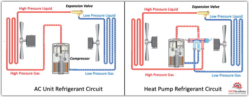
The reversing valve has two modes of operation, its either in heating or cooling mode. The reversing valve provides changes in direction for the refrigerant flowing through the system, it reverses the flow, hence reversing valve. The reversing valve is the refrigerant traffic controller, changing the direction of refrigerant flow based on the demand of the space controller. The reversing valve sends the hot gas discharge from the compressor either to the outdoor unit heat exchanger or the indoor heat exchanger.
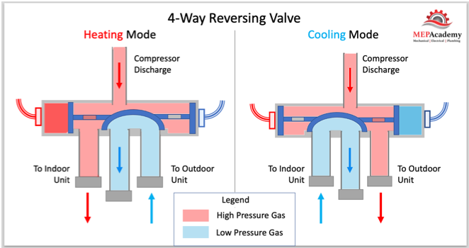
In relationship to the compressor, cooling is always accomplished on the suction side of the compressor, and heating is furnished on the discharge side. What the reversing valve does is switch the compressor discharge to go to the indoor coil when heating is required. It’s basically that simple, as the reversing valve acts as a traffic controller, sending refrigerant in one of two directions from the compressor.
To understand this better, we’ll walk through what happens in each season when heating or cooling is required.
Checkout these Heat Pumps hereHeating Mode
How HVAC Heat Pumps Work in Heating Mode. Starting at the compressor where the refrigerant is compressed causing the temperature and pressure of the refrigerant to increase. This high-pressure/high temperature gas (vapor) refrigerant will then enter the reversing valve where it will be directed to the indoor coil.
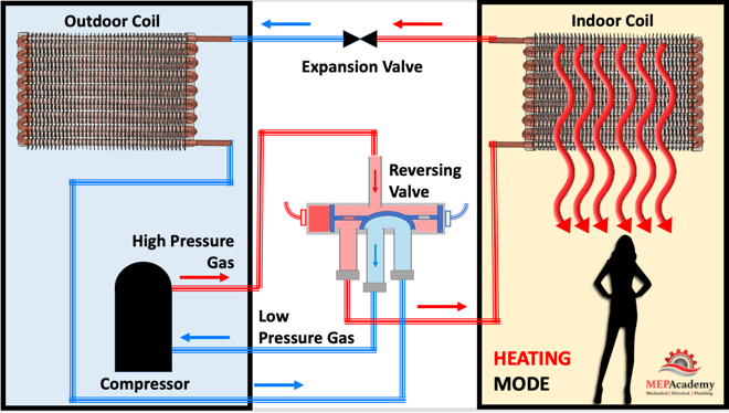
This high pressure, high temperature gas enters the indoor coil where cooler air from the space passes over the indoor coil absorbing some of the heat from the refrigerant, thereby heating the room, while causing the refrigerant gas to give up its heat and condense into a high-pressure liquid.
The refrigerant will than leave the indoor coil as a high-pressure liquid and enter the expansion valve where it’s pressure will be reduced causing it to become low-pressure liquid. See our video on expansion valves for more info.
This low-pressure liquid refrigerant will than enter the outdoor coil where it will absorb heat from the outdoors, causing the low-pressure liquid refrigerant in the outdoor coil to evaporate, absorbing the heat. This low-pressure refrigerant gas than enters the compressor where the cycle repeats itself.
Cooling Mode
How HVAC Heat Pumps Work in cooling mode, the heat pump acts the same as a standard air conditioners refrigerant cycle, whereby the condenser sends high pressure liquid to an expansion valve that lowers the pressure of the refrigerant going into the evaporator or indoor coil.
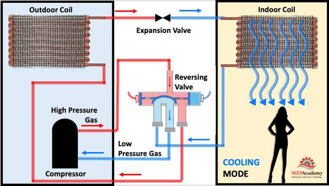
The heat from the space is passed over the indoor coil causing the refrigerant to boil or evaporate and absorb the heat from the air. This will cause the air to cool as its passes over the cold coil and head back to the space colder.
Checkout these Heat Pumps herePackaged vs Split System Heat Pumps
You can get a Heat Pump that is all contained in one box, called a Packaged Heat Pump, or you can install it in two pieces which is called a split-system, and is commonly found in residential projects.
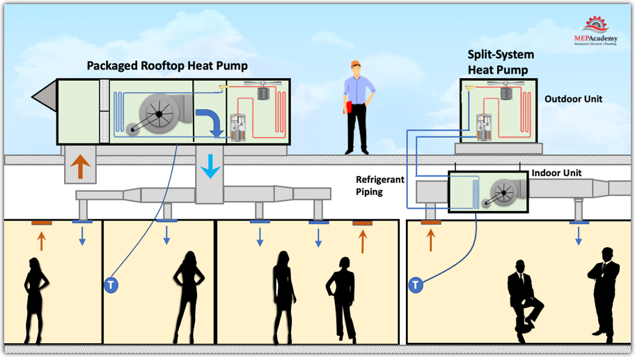
The split-system has an outdoor section, which houses the compressor and a heat exchanger with a fan in all air systems. The indoor section of a split system will have a heat exchanger and a fan. This is an all-air system, as each heat exchanger uses a fan. There are also water-sourced version which will cover now.
Water Source Heat Pumps
You’ll find the use of water source heat pumps in various sizes of commercial buildings. This allows for the use of a common water loop that works as a means of moving heat around. This heat can be discharged or absorbed from the water loop by the indoor heat pumps. The water loop is maintained between approximately 60 and 90 degrees. To help maintain the loop temperature within this temperature range a boiler is added to ensure enough heat is available during winter while the closed circuit cooling tower will reject additional heat during the summer or hot days.
The water is sent to a closed circuit cooling tower mounted outside on the ground or roof level. The water is in a closed loop, meaning that it never gets exposed to atmospheric elements. This keeps the heat exchangers of the water-cooled heat pumps clean by preventing impurities entering from exposed water sources.
With water-source heat pumps, heat rejection or absorption into the heat exchanger is through water. In an air-cooled system, a fan is used for heat transfer.
There are two commonly used types in the commercial industry, vertical and horizontal water source heat pumps, in addition to water source heat pumps used in ground source systems discussed later.
Vertically Stacked Water Source Heat Pumps
How HVAC Heat Pumps Work using vertically stacked units. There are lots of high-rise hotels that use vertically stacked water sourced heat pumps to provide heating or cooling to their guest-rooms. They are hidden behind the walls with a supply and return grill mounted to the face of the unit, and a temperature sensor nearby.
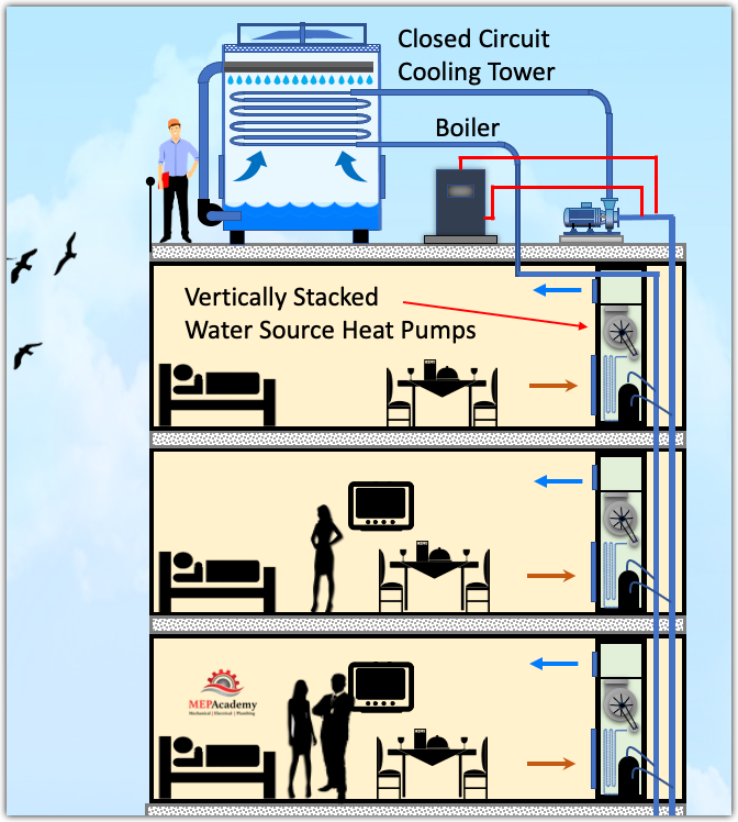
A vertically stacked water-source heat pump uses a closed-loop of water as a means of heat transfer. When in cooling mode the unit will reject its heat to the water loop, and while in heating mode it will absorb heat from the loop. The vertical heat pumps range in tonnage from 1/2 to 3 tons.
Vertical water source heat pumps contain the complete refrigerant circuit, with compressor, two heat exchangers, reversing valve and expansion valves.
Horizontal Water Source Heat Pumps
Various commercial buildings will have concealed horizontal water source heat pumps installed for each zone or room. These may also be found in hotel guestrooms, usually mounted above the entrance or bathroom with a stub of duct to feed a supply grille, with a ceiling mounted return grill. The return grill could also contain a filter.
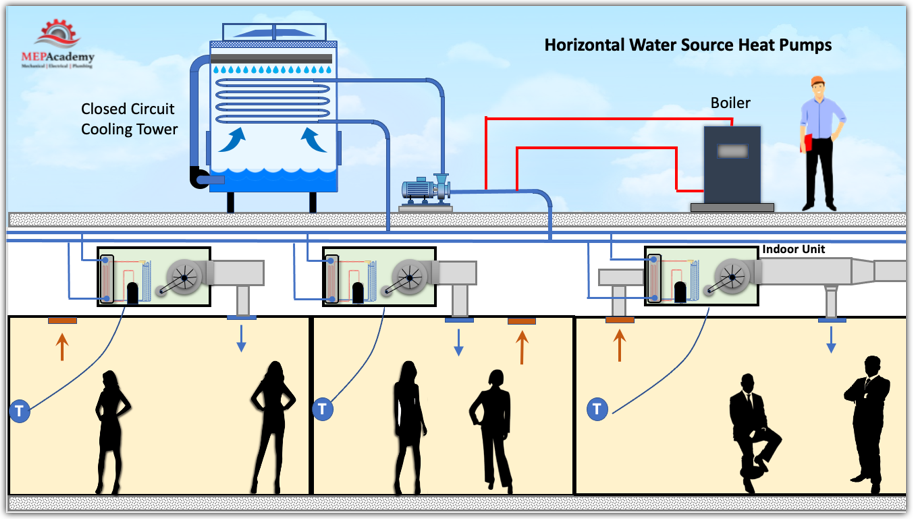
These units are also available for exposed locations, usually near an exterior wall to provide a method for fresh air. Just like the vertical stacked heat pumps, these horizontal heat pumps will have a closed circuit cooling tower mounted outside.
Ground Source Heat Pumps
The sun shining on the ground provides for heat energy to be stored in the soil. This underground stored energy can be used with ground source heat pumps. With ground source heat pumps the ground is used as a means of absorbing heat or providing heat.
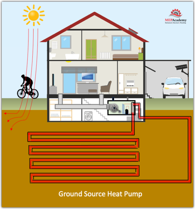
A pump circulates water through piping buried in the ground. This piping is connected to a heat exchanger in the heat pump where the heat from the ground will be absorbed or rejected into the refrigerant circuit.
Ground Water Source Heat Pumps
Bodies of water, like lakes or ground water can also be used as a source of energy. They use heat exchangers as a means of separating the refrigerant from the water. Water is mixed with antifreeze like glycol in some climates to avoid freezing and is pumped through a maze of hoses buried in the ground. The water circulates around the buried piping and then back to the heat exchanger where it transfers or absorbs heat from the refrigerant.
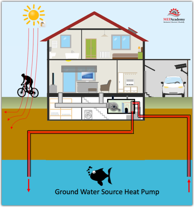
When using groundwater, there are two types, the open loop which is shown here, and a closed loop version. The open loop system uses a pump to withdraw water from a lake or underground aquifer and send it through the heat exchanger where it will absorb or reject heat into the refrigerant before being sent back into the body of water.
In a closed loop system everything happens the same except the piping is closed and circulates the same water and antifreeze mix.
Water sources can provide a method of passive cooling, whereby the compressor can be shutoff.
Checkout these Heat Pumps here