Home Blog Page 49

3 Phase Electricity – How it Works

3 Phase Electricity – How it Works. We’ll be demonstrating how 3 phase electricity works by first explaining how its generated, and how it differs from single phase electricity. We’ll also cover where 3 phase power is used in industrial and commercial buildings.

To watch the FREE YouTube version of this presentation, scroll to the bottom.

How is 3 Phase Electricity Generated?

If starting at the source of 3 phase power generation, we would begin at the power generation plant, whether that was nuclear, fossil fuel or another source. AC Generators convert mechanical energy into electrical energy, while the AC motor does the opposite, it converts the electrical energy into mechanical energy like turning the motor shaft of a pump or fan.

3 Phase AC Generator Converts Mechanical Energy into Electrical Energy

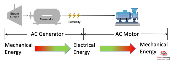
The AC generator could be a steam powered turbine fed by a boiler burning coal, gas, oil or another source, such as nuclear power or a hydroelectric dam. The steam or potential energy turns the generator that produces the 3 phases we’ll be discussing now. We’ll show you a coal burning plant convert coal into electricity later.

Michael Faraday - Electromagnetic Induction and Electromagnetism
Michael Faraday – Electromagnetic Induction and Electromagnetism

First we must pay tribute to Michael Faraday, an English Scientist who contributed to the study of electromagnetism and the principles underlying electromagnetic induction. AC Generators and Motors use electromagnetic induction as we’ll now explain.

Electromagnetic Induction

A magnetic field can be created in a conductor by passing electricity through it, or an electrical current can be induced in a conductor by passing a magnetic field past the conductor. We can accomplish this with three items, a conductor, electromagnets and movement between them.

There are many version of the AC Generator, one such version uses a rotating electromagnet to create a magnet field that conductors pass through, thereby creating electromotive force and inducing current to flow in the conductors. Another version would have the conductors moving and the electromagnets are stationary. The commonality is a electromagnet which creates a magnetic field and a conductor that is brought within this magnetic field.

3 Phase Magnetic Induction

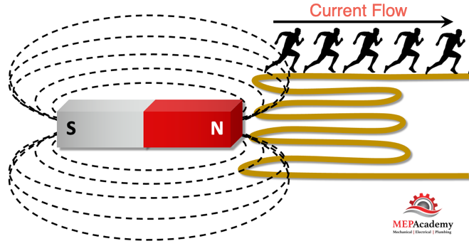
When the north pole of the Electromagnet passes the electrical conductor windings it induces current to flow in the wire. 

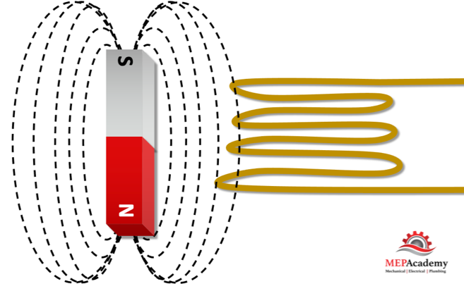
When the magnet is 90 degrees past the conductor windings than no current flows in the wire.

3 Phase Electricity Magnetic Induction - No current Flow
3 Phase Electricity Magnetic Induction – No current Flow

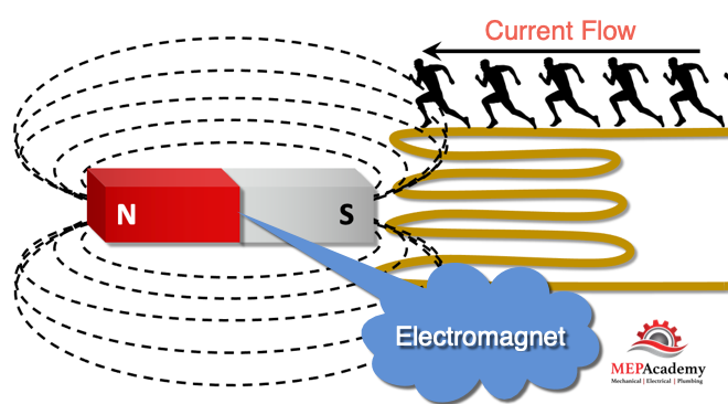
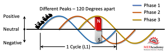
As the South pole of the electromagnet passes the conductor windings it causes the current to travel in the opposite direction as that caused by the North pole of the magnet. This causes the current to be alternating in direction as represented by the wave form.

3 Phase Electricity generated by Electromagnetism

There are three coils in 3 phase electricity, with an angle of 120 degrees between them.

3 Phase Electricity - Frequency in Hertz
3 Phase Electricity – Frequency in Hertz

What is 3 Phase Electricity

Using what we learned previously we can now assemble a basic 3 phase generator by adding three sets of windings, one for each phase. The previous single winding can be considered a single phase generator. Will need to put these windings in a housing to hold everything together.

Here is what a simple single phase generator might look like.

Single Phase Electricity

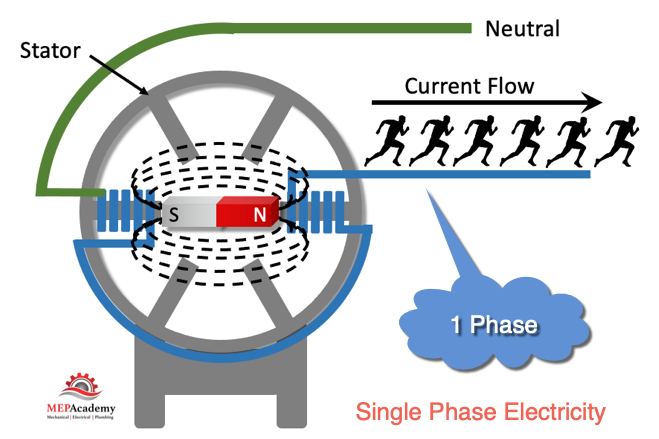
Now as the electromagnet rotates within the stator, its magnetic field cuts through the conductors inducing current to flow in an alternating back and forth pattern. Using only one conductor we get a single phase system.

Adding two more conductors we now get three phase electricity. The magnetic field of the electromagnet now penetrates the three conductors inducing current to flow in all three conductors. We get three separate phases that are 120 degrees apart giving us the most effective arrangement for power use.

3 Phase Electricity using an Electromagnet

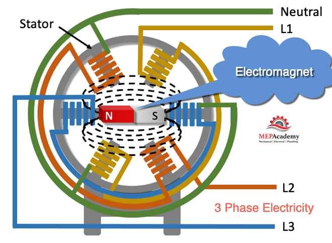
As the magnetic field of the North pole of the magnet reaches the nearest point of one of the conductors it will force electrons and current to flow in one direction. Then when the South Pole of the electromagnetic reaches that same conductor it will causes the electrons or current to flow backwards. This back and forth push and pull of the electrons or current in the three separate windings is how three phase power is created. 

While one conductor or winding is peaking in strength facing the North pole of the magnet, the others are 120 and 240 degrees away, awaiting their turn at the effects of the North pole of the magnet. This occurs 60 times in a second giving us 60 hertz, or if you’re in a country that uses 50 hertz, this will occur 50 times a second.

A complete rotation of all three phases equals one cycle, and in a 60 hertz system, that would mean 60 cycles or rotations of the rotor within the stator housing every second, for a 50 hertz system, 50 cycles per second. The cycles per second is called frequency, and is either 50 or 60 hertz. Remember motors with VFD’s can very their hertz, and if you aren’t familiar with this concept then see our video on VFD’s, Variable Frequency Drives.

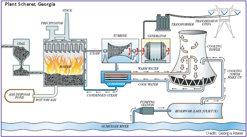
Coal Burning Electricity Plant

The 3 phase electricity is generated here using dirty coal. Coal is sent to the boiler where it is burned to create steam that turns a turbine in the generator that produces the electricity. The electricity is transmitted over high voltage lines to location that will consume the electricity. The high voltage electricity will be converted to lower voltage by running it through a transformer.

Coal Powered Electricity Generation

These transformers can be located on an industrial or commercial property where the voltage will be reduced to something that is at a proper level for the equipment it will power. 

Depending on the configuration of the transformer, it can be setup as a delta or Wye type transformer providing all the various voltages required in the building. From this 3 phase electricity everything in the building can be powered whether requiring single or 3 phase. The lights in your home will use 115 volts or something similar while a commercial building may use 277 volts, single phase for their light fixtures, as 277V is more efficiently distributed.

Your home will only require single phase electricity while commercial and industrial buildings can use the more efficient and powerful 3 phase power for their equipment, such as Pumps, Fans, Chillers, Elevators, hospital equipment, etc. The 3 phase power allows the industrial and commercial buildings to also use just a single hot wire to get single phase to run office equipment like computers, vending machines, calculators and other low voltage items. 

How 3 Phase Electricity Works

Ohm’s Law

Learn how OHM’s Law Works, and how to use it to solve problems.

To watch the FREE YouTube version of this presentation, scroll to the bottom.

What is Ohm’s Law

There is a relationship between Voltage, Current and Resistance that is easily explained using Ohm’s Law. The German physicist by the name of Georg Ohm develop the theory that we are going to explain here.

What is Ohm's Law and the relationship between voltage, current and resistance.
What is Ohm’s Law

We can calculate any of the three factors that make up the OHM’s law, if we have any two of the factors. Here are the three versions of the formula. 

Voltage (V) = Current (I) x Resistance (R).

Current (I) = Voltage (V) / Resistance (R).

Resistance (R) = Voltage (V) / Current (I).

OHMs LAW WHEEL

The formulas are easily remembered by using the Ohm’s Law Wheel. You may also see version of this using a Triangle.

Ohm's wheel is an easy way to determine how to calculate either Voltage, Current or Resistance.
Ohm’s Wheel

Each of the three formulas is represented by one of the three wheels, with the product were trying to solve colored red. All you have to do is cover the red letter or the letter that you’re trying to solve for. For example, if you cover the “V” for voltage, than you’ll only see the Current (I) and Resistance (R). When the letters are side by side you multiply, when the “V” voltage is over any letter, than you divide into the voltage.

Ohm's Wheel - Easy method for determining formula for Ohm's Law for Voltage, current and resistance
Ohm’s Wheel – Easy method for determining formula for Ohm’s Law

Just cover up the letter you want to solve for, and the formula will reveal itself.

Solving for Amps

Using a digital meter, we can determine how many amps are flowing through a circuit like this here.

Ohm's law for Solving how many Amps
Ohm’s Law for Solving for Amps

If we cover up the (I) of the Ohm’s wheel with an effort to solve for the amps or current flowing through the system, we can see that the two known values of 6 volts and 2 ohms of resistance work perfectly within the formula.  This gives us 6 volts divided by 2 ohms = 3 amps.

Doubling the Voltage

By putting batteries in series, you add up the total of the voltage. As shown in the example here, the two 6-volt batteries in series equal 12 volts.

Ohm's Law for determine Amps when Voltage is doubled
Ohm’s Law for determine Amps when Voltage is doubled

By doubling the voltage and keeping the resistance the same, we have effectively doubled the amps. We now have 12 volts divided by the same 2 ohms of resistance to get twice as many amps as previously, 6 amps instead of 3.

Remember since voltage is always in the numerator position, anytime you increase the voltage there will be an increase in amps if the resistance stays the same.

Doubling the Resistance

By doubling the resistance and keeping the voltage the same, we have effectively cut the amps in half. 

Doubling Resistance in an electrical circuit will cut the amps in half.

The current or amps are inversely related to resistance. As resistance goes up, the current goes down, and vice versa, as the resistance in Ohms decreases, amps will increase in the circuit.

Resistance versus Amps in an Electrical Circuit with fixed voltage

Solving for Resistance (Ohms)

To find the (R) resistance in a circuit, cover up the “R” in the Ohm’s wheel and enter the two known values of Voltage (V) and Amps (I).

Solving for Resistance using Ohm's Law
Solving for Resistance using Ohm’s Law

By knowing the voltage and measuring the amps flowing through the circuit we can determine the resistance. There are three 6-volt batteries that are equivalent to 18-volts, plus the digital meter reads 3 amps. With these two values we get 18-volts divided by 3 amps equals 6 Ohms.

Solving for Voltage

Solving for the voltage requires knowing the value of the resistance and the current. Using a digital meter, the amps can be determined. With this we enter the resistance and amps into the formula to discover the voltage. 

Solving for Voltage using Ohm's Law
Solving for Voltage using Ohm’s Law

Voltage is the force that pushes the amps through the circuit while ohm’s provide resistance to the current flow.

Other ways of Measuring

Remember there are other ways to determine the voltage, current and resistance in a circuit, but this presentation was meant to demonstrate the use of Ohm’s Law. 

Voltage can be determined directly by connecting to the terminals of the batteries using a multi-meter. 

Multi-meter for measuring voltage, amps and resistance

Measuring Resistance can be done with the same digital meter by setting the meter to read ohms and setting the two probes on each side of the resistor. The multi-meter has an internal battery that sends a current through the resistor.

Measuring Current or amps can be done as shown above or by using a clamp on type of amp meter that isolates a wire. Instead of being connected in series with the circuit the amp probe encompasses the wire. These clamp on meters can measure both AC and DC current.

Amp Meter
Amp Meter – Clamp
Learn what Ohm’s Law is and How to calculate Voltage, Current and Resistance Easily

Power Factor

How a Power Factor Works.

We’ll learn what a power factor is, and how to correct a bad power factor. How to calculate the power factor. What causes a poor power factor, and what can be used to make the power factor better. 

To watch the FREE YouTube version of this presentation, scroll to the bottom.

First, we’ll introduce the characters that are involved in calculating the Power Factor. There are three terms in addition to Power Factor that you need to know. 

Active Power – Reactive Power – Apparent Power

#1 We have the “Active Power” in (kw) which is the real electrical power required by motors, heaters, computers, ballast-based lights, transformers, etc. This active power is transformed into heat, light and mechanical energy. This is the work we want done in our buildings. Alias, Real power, True Power.

#2 We have “Reactive Power” in (kvar) which supplies the equipment in the building that uses magnetic circuits, like motors and transformers. This reactive power is what causes all the problems if not controlled, which will explain shortly.

#3 We have “Apparent Power” in (kVA) which is a result of the mix of the first two types of power. The larger the Reactive Power, the greater the Apparent Power. Will explain all these terms in greater detail. Alias, Total Power

#4 Is the “Power Factor” which is derived by dividing the “Active Power” into the “Apparent Power”. Kw/kVA


What is a Power Factor?

A power factor represents how efficiently a building uses the electrical power that the utility company provides. A power factor of 1 is the best factor, which represents 100% effective use of the power delivered. This is unlikely as there are factors that affect the quality of the power within a facility or building, such as induction motors.

Think of a power factor as a Grade given to a building by the utility company, like your teacher would give you a grade for a math or English class. The grade indicates how well the building uses the electrical power that the utility company provides, and the scale is 0 to 1, with 1 being the best factor or grade. You can think of it also as 0% to 100%, with 1 equal to 100%.

The possible punishment for a building that gets a bad grade or poor power factor is an extra fee charged on their utility bill and loss of additional kw capacity. This fee can add up to a large amount of money for a customer with a lot of induction load. 

Power factors that are below 1.0 causes the utility company to generate more power to meet the demand. This causes an increase in the generation and transmission cost, which is passed on to the customer in the form of a reactive power (kvarh) fee or a percentage surcharge on their utility bill.

We can represent these three terms using a power triangle and demonstrate how reactive power effects apparent power.

Power Factor Triangle

You can see using this power triangle that as the Reactive Power gets larger it requires more Apparent Power (kva) from the utility, but the Active/True Power remains the same. The true power (kw) is what the building needs to run its motors, and the reactive power is just making things more expensive for the utility company and the customer. The reactive power needs to be reduced or controlled as much as possible.

Power Factor (PF) = KW / KVA

The power factor is the True/Active power (kw) that the building requires to power its machinery divided by what the utility company provides in Apparent Power (kva). The power factor tells us how efficient the building is in using the power. 

Power Factor Formula

This means that the lower the reactive power the less the customer pays for apparent power (kva) to run their load (kw). Remember the utility must deliver the required apparent power (kva) even though the customer only needs the True/Active power (kw). 

As an example, if a building required 1,000 KW of power and had a power factor of 100%, then it would only require 1,000 KVA of generating and distribution network capacity. If the power factor dropped to 80%, however, 1,250 KVA of capacity would be needed. The lower power factor has an adverse effect on generating and distribution capacity.

PF Example. What happens when your PF worsens.
Power Factor Example

The lower the power factor the greater the burden on generation, distribution, and networks, due to excess KVA.

What Causes Reactive Power

Reactive power is caused by something that is found in just about every building, and that’s induction motors. Induction motors are required in every industry to perform work, so we can’t get rid of them, so there will always be some reactive power.

AC Induction Motors

The cause of all the problems begins with the AC (Alternating Current) motors. Induction motors use magnets that cause power quality issues. We need magnets to get motors started. If you have a lot of motors in a facility, like industrial buildings, then you’ll have a poor power factor unless something is done to correct it.

How to Correct Poor Power Factors

How does a building owner go about correcting their power factor to reduce wasted energy and cost, while increasing distribution and transformer efficiencies?

By adding capacitors to the system where induction motors are the main cause of the problem, the building can improve its power factor and network efficiency. The effect of Capacitance is opposite that of inductance.

Capacitors can be in various places within the electrical system to improve the power factor. 

As this single line electrical diagram shows, power factor correction equipment can be located centrally (CPC) to handle the complete building, or regionally (RPC) within the building, or at individual Local (LPC) loads, such as motors.

Power Factor Correction using Capacitors. Location varies as shown above.

Locating the capacitor at the motor corrects any interference coming from the motor. If you have a lot of motors, then you might consider locating the capacitor at the service entrance switch gear to avoid having capacitors all over the facility. 

Wherever the capacitor is located it will improve the power factor between that point and the power source. Remember that this means the power factor between the capacitor and the load or motor will remain unchanged.

Capacitance causes voltage to lead current, while inductance causes current to lead voltage.

Why Correct the Power Factor?

As we previously showed, the building can free up additional electrical capacity (kw), while reducing system losses in cables and transformers. These system losses heat up the electrical power lines which causes a loss in their capacity, as the reactive power contributes to those loses and thermal overloading. Improving the power factor reduces power loses, saves energy, and lowers the buildings overall CO2 emissions.

A poor factor (PF) will cause the line current to increase, causing losses in the distribution system and transformers. Even though the building uses the same Real Power, the lower factor (PF) cost the utility company more to generate and distribute.

Improved Power Factor and Increased Power (kw) Capacity

Having higher current requirements due to lots of Reactive Power could result in the overload of transformers, less available active power (kw), increased temperatures of electrical supply cables, higher voltage drops, increased energy consumption and cost. The building would require larger wiring, transformers, switches, etc., because of higher current and KVA.

Therefore, it’s important to correct Reactive Power by adding capacitors. The capacitors will produce reactive energy in opposition to the energy absorbed by induction loads such as those produced by magnets in motors. This is how Power Factor Correction is achieved. Basically, the capacitor is providing the reactive power required by the motor, so the utility doesn’t have to.

This will result in lower apparent power, improved power factor, increased capacity available, reduced power losses, and reduced cost to the building.

Increased Available Power (kw)

By increasing the power factor, you increase the available power (kw) for the facility. This is very useful if a building has reached its limit in the available power and needs to add additional power consuming devices. 

Increased Power Capacity with Reduction in Reactive Power

Increasing the power factor (PF) by reducing reactive power (kvar) and maintaining the same apparent power (kva), a building can increase its (kw) usage capacity. Improving the factor free’s up additional capacity being wasted by reactive power. If you don’t choose to use the added capacity (kw), then your Apparent Power will be reduced along with the energy cost.

As the chart shows if a building has a power factor of 0.7 and increases it to 0.9 it increases the available power by 28%.

Power Factor Table
Power Factor Table

Savings on Electric Utility Bills

Utilities usually start charging a facility when their power factor drops below 0.90 to 0.95. The utility can charge based on the apparent power (kva) instead of the True/Active power (kw).

Buildings are charged for the circulation of Active Power over a period of time as indicated by kwh (kilowatt hours), while some utilities also charge for Reactive Energy over a period of time as indicated by kvarh (kilovolts-ampere-reactive hours). By improving the power factor, this charge will also be reduced or eliminated. The savings from the reduced charges can help pay for the added expense of making the improvements to the power factor.

Reduction in Cable Sizing

By improving the power factor, less current is required, which means smaller conductors. A factor of 0.5 could require cross-sectional cable sizing twice that of a power factor of 1.0. As the table shows the increase in cabling size due to a worsening factor.

Power Factor effect on Cable Sizing

Reduction in Voltage Drop

The voltage drop will be improved upstream of where the capacitors are installed and avoids overloading the utility network.

Sizing of Capacitors for Correcting Power Factor

To determine the size of a capacitor or the total kvar needed for a single load or entire power system we’ll need to determine the kw factor by gathering the following data: Actual Power (kw), existing and desired power factor.

Sizing Capacitors for PF Correction
Sizing Capacitors for Power Factor Correction

With this information you can use an online calculator or manufactures chart to discover the required KVAR. The KVAR rating of a capacitor shows how much reactive power the capacitor will supply.

The formula is KVAR = kW x kW Factor

How a Power Factor Works

How a Condensing Boiler Works

How a Condensing Boiler Works. We’ll explain how condensing boilers or condensing heaters work and their residential and commercial applications. Why are condensing boilers more efficient than the standard non-condensing boilers? We’ll explain what you should think about before adding a condensing boiler to your home or commercial property.

To watch the FREE YouTube version of this presentation, scroll to the bottom.

How a Condensing Boiler Works

Before we explain how a condensing boiler works, it’s best to understand how a conventional non-condensing boiler operates.

Checkout these Condensing Boilers here

How Standard Boilers Work

The conventional non-condensing boiler uses one heat exchanger to transfer heat between the burning fuel and the water. As the water enters the heat exchanger it absorbs heat from the combustion of fuel that has been ignited with a mixture of air. 

Standard Boiler (Non-Condensing)

The water enters cold, and leaves heated for use in heating spaces or domestic water purposes. The high temperature flue gas is exhausted out to the atmosphere through a vent. This is wasted heat and energy that you have paid for. If this boiler is 75% efficient, then basically you’ve exhaust 25% of your money out the flue. The condensing boiler makes use of this heated flue gas before its exhausted to the atmosphere.

How Condensing Boilers Work

How a Condensing Boiler Works by using two heat exchangers instead of one. This additional heat exchanger is used to capture the heat from the flue gases being exhausted. It’s called a condensing boiler becomes it removes latent heat (moisture) from the hot flue gas causing water to condense out of the flue exhaust air. This moisture collects at the bottom of the heat exchanger and must be drained to an approved drain receptor, much like you would with an air conditioners condensate drain. Since the heat exchanger is exposed to moisture it must be made of non-corrosive material, such as stainless steel.

Checkout these Condensing Boilers here
Condensing Boiler
Condensing Boiler

This condensate from the boiler must be treated before it is allowed into the drain system, because it’s considered acidic. This is accomplished by adding a little inline filter on the drain line. The filter may contain limestone which absorbs some of the acidic nature of the condensate, neutralizing it before it enters the drain.

Condensing Boiler Condensate is Acidic

The incoming cold water is preheated as it passes through the secondary heat exchanger before it enters the primary heat exchanger. This secondary heat exchanger is what increases the efficiency of the condensing boiler. The secondary heat exchanger gives the condensing boiler a second opportunity to absorb heat from the energy expended during combustion, by absorbing heat from the exiting flue gases. By capturing heat that would otherwise be wasted the condensing boiler achieves higher operating efficiencies. 

These higher efficiencies are why condensing boiler are mandated in some jurisdictions, and why utilities often offer rebates. Check with your local utility company to see if rebates or incentives are available for changing a conventional boiler to a condensing boiler. Non-condensing or standard boilers have a range of efficiency from 75% to 84%, while condensing boilers can exceed 90% and all the way up to 98%. This will allow you to save on your annual fuel cost while also helping the environment.

Non-condensing Boiler vs Condensing Boiler

If you spend a dollar on fuel for your standard boiler at 75% efficiency, then you are throwing away 25% of your money through the heated exhaust gases. This is $0.25 cents for every dollar you spend. With a condensing boiler or heater that is 95% efficient, you are making your dollar more efficient as now only 5% is wasted in the exhausted flue gas. This means that for every dollar you spend, only $0.05 cents is wasted on flue gas exhaust.

Condensing Bolers Efficient Use of Fuel

Within the condensing boiler, the flue gas and water travel in opposite directions. The flue gas first enters the primary heat exchanger, while the water first enters the secondary heat exchanger.

Checkout these Condensing Boilers here

Flue Gas Material

Since a condensing boiler has much lower flue gas temperatures, most manufactures recommend the use of PVC or CPVC. Installing plastic piping is easier and less expensive than the standard metal flues used in conventional boilers.

For those of you who love the science behind the operation, just remember that the latent heat from the condensation provides around 970 Btu/Lb. of latent energy. This latent heat is what contributes to the increased efficiency, as this heat would otherwise be exhausted to the atmosphere. Boiler efficiency increases as the return water temperature decreases. Condensation occurs below 130F (54.4C), with the greatest efficiencies occurring the closer the return water gets to 60F (15.5C). 

Condensing Boiler Efficiency

In commercial applications its best to get your supply temperature down to 140F (60C) as this provides an opportunity for better efficiencies. The engineer will have to make sure that the heat exchangers or whatever is receiving the heating hot water can operate at lower supply temperatures, as this will affect the surface areas of coils.

Considerations for Retrofitting a Non-condensing Boiler to a Condensing Boiler

Here are some main points to consider in commercial applications when retrofitting a project that has a conventional non-condensing boiler to a new condensing boiler.

  1. Keep return water temperature as far below 130F (54.4C) as possible to take advantage of the increased efficiency at these lower temperatures.
  2. Condensate drain piping with an inline filter to neutralize the acidic condensation. This includes the requirement for an approved drain receptor.
  3. Boiler flue/stack to be installed using PVC or similar material
  4. Heat Exchanger to be made of non-corrosive material, such as stainless.
  5. Higher delta-T for existing fan coils or heat exchangers. Do they have the ability for lower flow (GPM) with greater temperature difference using a lower return temperature?
  6. The old system might have been designed with a smaller Delta-T, maybe 20F (11C) (The difference between Supply & Return Water Temperatures). The new condensing boiler can run on a wider range of Delta-T, such as 30F to 50F (17C to 28C), allowing for lower GPM’s and pressure drops through heat exchangers. This saves on pump energy due to reduced flow and head.

Applications for using lower return water temperatures and a condensing boiler include, residential water heating and swimming pools, water-source heat pumps, hydronic radiant heating, snow-melt systems and geothermal. 

How a Condensing Boiler Works