Home Blog Page 52

How Variable Frequency Drives Work in HVAC Systems

We’ll discuss the basics of How Variable Frequency Drives (VFD’s)Work in HVAC Systems, also referred to as Variable Speed Drives (VSD’s), which are used in the Mechanical Construction Industry for the control of motors that run fans, pumps, and compressors. We’ll discuss where VFD’s are used in the MEP Construction Industry, Identify the key components of a VFD and how to select a Variable Frequency Drive.

If you prefer to watch a Video of this presentation than scroll to the end this article for our YouTube Video.

Be sure to shutoff any electrical power when working with a VFD.

Motor control equipment and electronic controllers are connected to hazardous line voltages. Extreme care should be taken to protect against shock and possibility of a fatality.

Where are VFD’s used in the Mechanical Construction Industry?

Pump Control with VFD’s

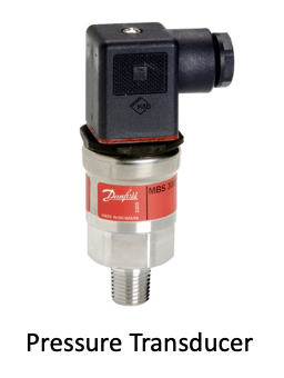
The use of VFD’s to control the motor speed of pumps is widely used in commercial construction projects. There are various control strategies, and as the image shows this one uses a “Differential Pressure Transmitter” to control the speed of the pump, which controls the flow (GPM) based on demand. 

How to control pumps using Variable Frequency Drives VFD's
How to control pumps using Variable Frequency Drives VFD’s

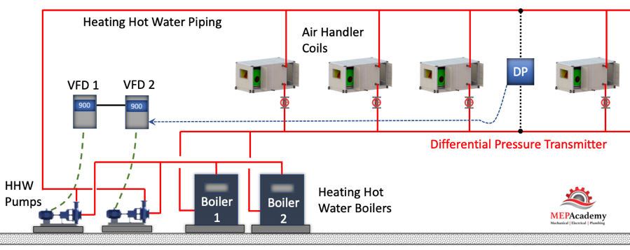
As the HHW control valves open due to an increase in demand for heating hot water, the pressure drops in the piping which is sensed by the Differential Pressure Transmitter. The transmitter sends a signal to the Variable Frequency Drive to speed up (increase flow – GPM), causing the pump to push more water through the pipes. The opposite happens when the heating hot water valves start to close because the space is warm enough. The valves start closing causing an increase in pressure in the piping which is sensed by the differential pressure transmitter. The transmitter sends a signal to the Variable Frequency Drive to slow down the pump motor, reduces the flow (GPM).

Checkout these Variable Frequency Drives here

Fan Control with VFD’s

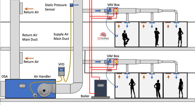
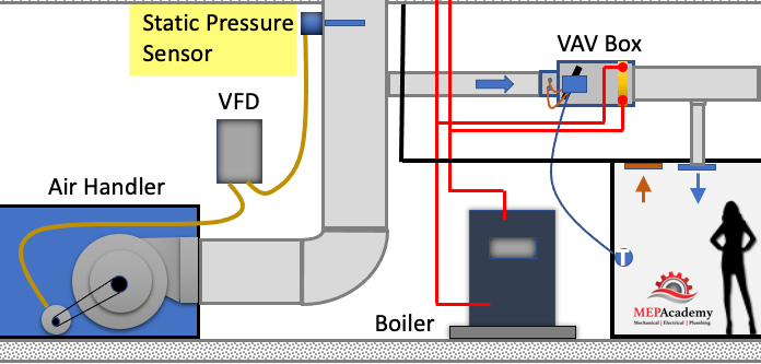
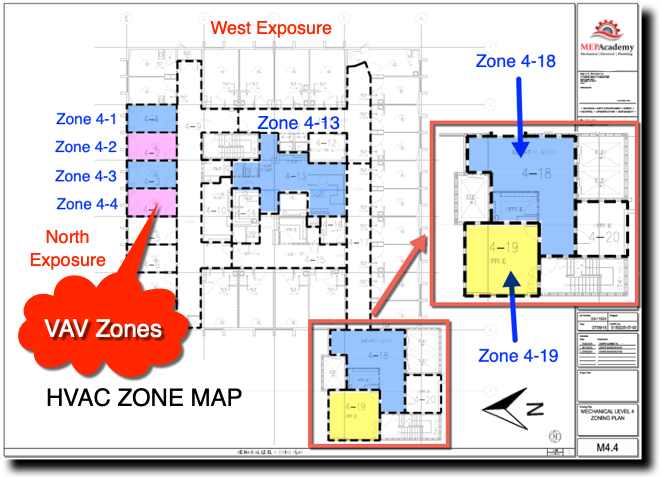
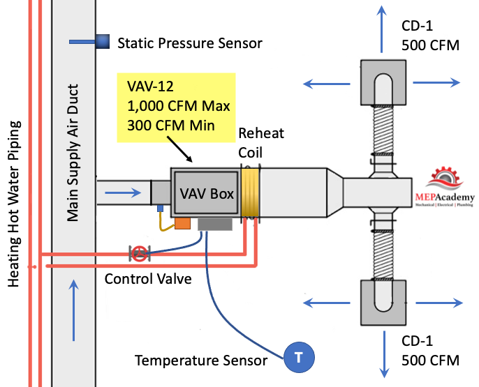
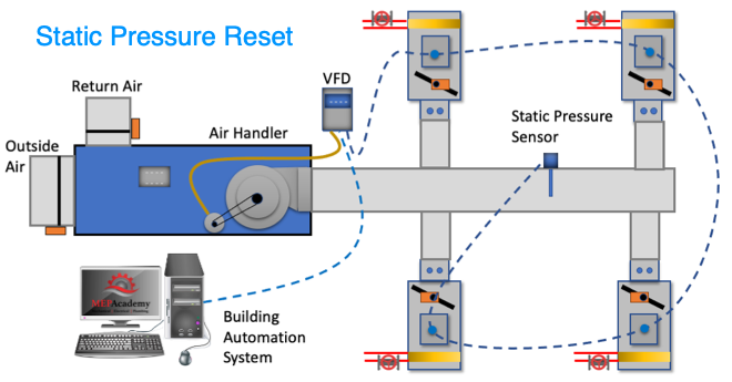
The theory is the same for controlling the speed of the fan motor. There is some form of monitoring of the supply air duct which will cause an adjustment to the speed of the fan. In the scenario below we show that a “Static Pressure Sensor” is located two-thirds of the way down the main supply air duct. The sensor will pick up changes in pressure within the duct.

Controlling a Fan Motor using a Variable Frequency Drive - VFD
Controlling a Fan Motor using a Variable Frequency Drive – VFD

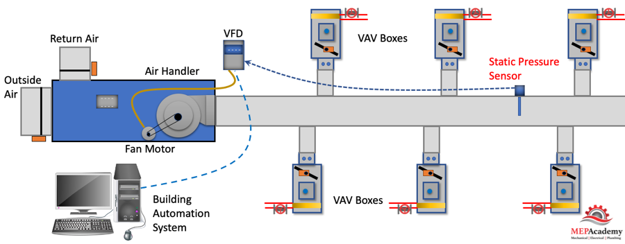
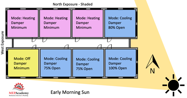
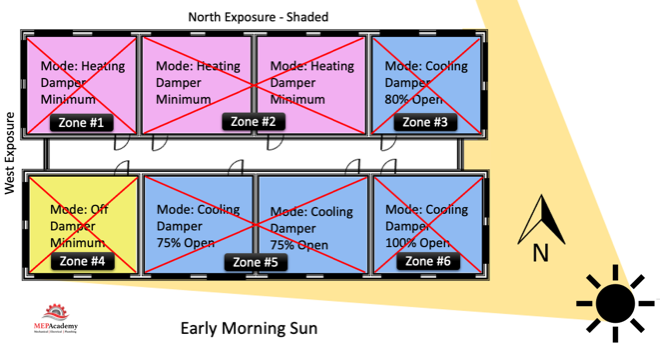
As the Variable Air Volume (VAV) boxes begin to open their dampers because of an increase in cooling demand, the pressure in the supply duct drops. When the pressure in the supply air duct decreases, the Static Pressure Sensor sends a signal to the Variable Frequency Drive to increase the speed (RPM) of the fan motor, causing an increase in CFM. The opposite happens when the VAV box dampers begin to close because the spaces are cold enough. As the dampers begin to close the pressure in the supply air duct increases, causing the Static Pressure Sensor to send a signal to the VFD to slow down the motor of the fan, reducing the amount of CFM. See our video on Variable Air Volume Systems.

Compressor Control with VFD

Chillers come with various options for variable speed control. Check with your Chiller manufacture for chillers with Variable Speed Drives. As the load in the building decreases, the chiller can change the speed of the motor that turns the compressor, thereby reducing the energy consumed.

Compressor motor on a Chiller using a Variable Frequency Drive - VFD
Compressor motor on a Chiller using a Variable Frequency Drive – VFD

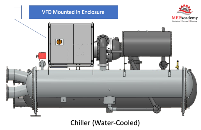
By reducing the speed of the compressor the output tonnage of the chiller is matched to the demand. Variable Speed Drives (VSD) come mounted in an enclosure mounted on the chiller.

Checkout these Variable Frequency Drives here

Old Methods of Volume Control

To control the volume of air (CFM) or water (GPM) using constant speed motors required putting an artificial load on the system. This method of flow control waste energy. Fans used dampers to impose flow restrictions, while pumps used valves (throttling) to dial back the GPM flow of water or just bypassed the water. These methods generate restrictions to flow that waste energy. Controlling the varying flow requirements with a VFD saves on this lost energy.

In the HVAC industry the use of Variable Air Volume System is very common. To control the various cooling and heating load fluctuations during the year the Air Handler fan will vary the volume (CFM) delivered to the space. The same applies to the Chilled Water, Heating Hot Water or Condenser Water flow (GPM) through the pipes as the load on the building changes through-out the year. In older HVAC piping systems with constant flow pumps the use of 3-way valves was common. Instead of reducing the flow (GPM), the water would bypass the coil through the 3-way valve. Obviously this is a waste of energy as the pump is just circulating water that is not needed.

What Is the Purpose of a Variable Frequency Drive VFD?

The main purpose of a Variable Frequency Drive (VFD) is to vary the speed of a motor by varying its frequency and voltage to provide for energy savings. By increasing the frequency you can increase the speed of the motor, and by decreasing the frequency you can decrease the speed of the motor, it’s basically that simple. 

Many of the existing motors that control mechanical equipment were originally designed to run at constant speed, which isn’t energy efficient. These older motors were either in the on or off position and used some form of artificial resistance to control flow.

Variable Frequency Drive - VFD
Variable Frequency Drive – VFD

How to Choose a Variable Frequency Drive VFD

Selecting a Variable Frequency Drive can be very simple when you know the Voltage, Current and the Power Rating.

When bidding a plans and specifications project the mechanical engineer will have sized and documented the required VFD on the equipment schedule. If you’re doing a Design/Build project or Retrofit where you’ll be responsible for the selection of the variable frequency drive, then knowing the basic’s for selecting a drive is crucial. If you’re not comfortable with selecting a Variable Frequency Drive there are many VFD suppliers that will help you choose the correct drive.

Checkout these Variable Frequency Drives here

Here are a few things to consider when selecting a Variable Frequency Drive (VFD) for an existing motor on your project. Values are from example motor nameplate below.

  • Full Load Amps (FLA) 40-37/18.3
  • Horsepower (Hp) 15
  • Voltage (V) 208-230/480
  • Speed (RPM) 1775
  • Motor Type – (Inverter-duty Rated)
  • Method of Control I/O (Static Pressure Sensor, Differential Pressure Transmitter)
  • NEMA Enclosure type. (Inside, Outside, Exposure to elements) 

The first place to start on an existing motor is the motor name plate. This is where most of what you need can be found. Hopefully the building engineer hasn’t removed them or painted over them.
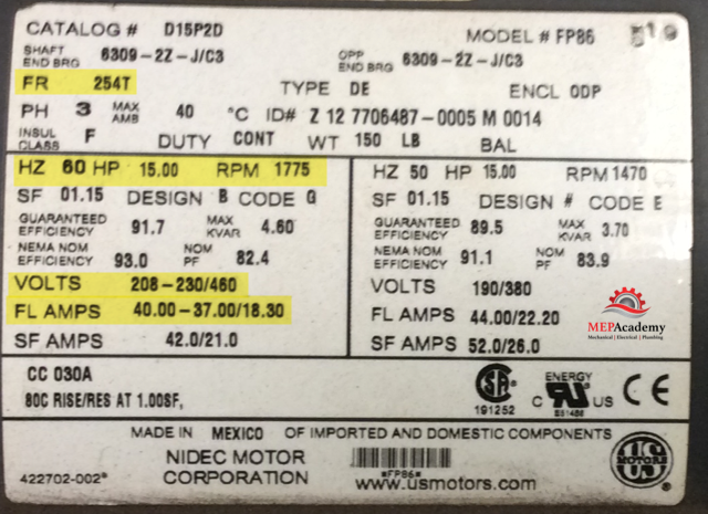
Motor Nameplate
Motor Nameplate

Motor Nameplate

The motor name plate may indicate more than one voltage and its corresponding amperage. The above name plate indicates 230 and 460 volts, with a corresponding 37 and 18.3 amps. The higher the voltage the lower the amps.

Full Load Amps (FLA)

The full load amps (FLA) is one of the important aspects of the Variable Frequency Drive VFD selection process. For existing motors this number will be on the motors nameplate, and shown as 40-37/18.3 on example nameplate. Why three values? Each FLA corresponds to what voltage is used, either 203 Volts (40 FLA), 230 Volts (37 FLA) or 460 Volts (18.3 FLA)

Frame Number

The NEMA frame number can be two or three characters and represents the distance from the center of the motor shaft to the center bottom of the mounting plate. Such as in our example of a frame number of 254T. This equals 254/16 = 15.875” 

Method of Control

If the VFD is for controlling a fan in a VAV Air Handler, then the controller may be a “Static Pressure Controller”, see our Video on Variable Air Volume Systems that explains this further. If for a pump, may be your using a “Differential Pressure Controller”. Whatever system variable is being measured the Input and Output (I/O) signals need to be setup in the VFD.

NEMA Enclosure Type

The Variable Frequency Drives are usually located in Mechanical Rooms or Outside near the equipment. Depending on the type of environment that surrounds the VFD, there are various solutions for the enclosure type as indicated by the NEMA number. The most common in the Mechanical industry is NEMA 1, 3R and 12. 

Variable Frequency Drives - VFD's (Small to Large Horsepower Drives)
Variable Frequency Drives – VFD’s (Small to Large Horsepower Drives)

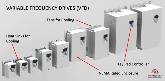
NEMA 1 Rated enclosures are made for Indoors with no water protection. NEMA 3R is rated for Indoor or Outdoor use, and where rain, snow or ice may form. NEMA 12 is rated for Indoors and with dust, lint and other dirt circulating in the air, along with minor water splashes. There is an enclosure for any environment.

Since VFD’s produce heat during operation, this must be part of the consideration when selecting a ventilated enclosure versus a cooled enclosure. Avoid locating a VFD on a heated wall or in direct sunlight. 

Checkout these Variable Frequency Drives here

Variable Frequency Drive – VFD Components
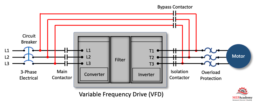
Bypass

The bypass provides a means for circuiting around the drive and providing power to the motor. You have to be sure that in bypass mode the motor still has some form of overload protection. Purchasing a Bypass adds substantial cost to a VFD. If its not needed or you can afford some down time with the equipment, then avoid purchasing a bypass or if you have several VFD’s of the same size, just purchase an extra drive for emergency replacements.

Variable Frequency Drive with Bypass

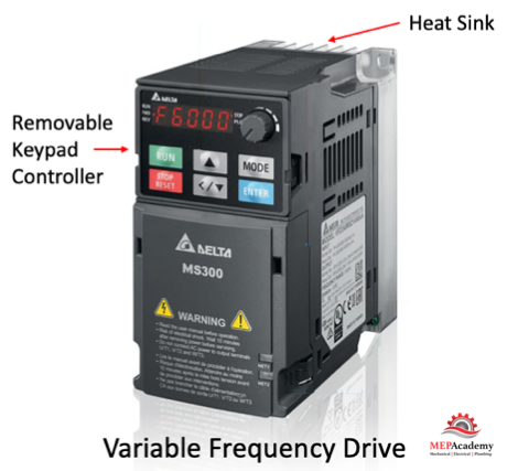
VFD Keypads and Control Panels and Remote Monitoring

If the location of the VFD is inaccessible or inconvenient for the maintenance staff, you could mount the VFD’s Keypad remotely. You may need additional cabling, so check with the VFD manufacture.

Navigating is easy using the control panel to set various parameter values. Various VFD manufacturers drives have the capability of copying settings from one drive to others. The control panels provide a touchscreen graphical display in various sizes from 3.5” up to 15”

Look for optional remote monitoring that allows you to view and control the drive from any location with web access.

The available menu items will vary by VFD manufacturer and how they are displayed, but there are some basic common features. There will be a way to adjust the speed, bypass the VFD if provided with a Bypass, alarm and fault indicators, on/off/auto, indication that either the I/O Terminal/Keypad or Communication Bus is chosen for control of start/stop – signals.

Input Line Reactors and Harmonics

To protect the VFD from the utility companies possible power fluctuations an input line reactor is installed. The Input line reactor also helps mitigate the harmonics associated with the use of variable frequency drives.

Physical Size

Small drives can be anywhere from 12” in height to over 60”. The weight of a small drive can be 10 pounds to over 500 pounds for larger drives.

VFD Cooling Requirements

There are two methods to keep Variable Frequency drives cool; air-cooled and liquid-cooled. Liquid-cooled is used on larger VFD’s, so most likely you’ll be dealing with air-cooled drives. Cooling is required to remove heat from the semi-conductors and ancillary devices used in the VFD.

The VFD’s require space around them for the proper flow of air through the cabinet to allow for cooling the drive. Be sure to check the mounting instructions to avoid overheating a drive and causing premature failure. Small VFD’s require anywhere from 40 CFM to over 1,000 CFM for larger drives. Check the drive manufacturers requirement for space around the drive and their method of cooling the unit. The area around the air-cooled VFD should be kept clean, dry and free of dust.

Three Main Components of a VFD

The following are the three main components that convert AC Voltage to DC Voltage and then back again using a simulated AC Voltage.

Three Main Components of a Variable Frequency Drive - VFD
Three Main Components of a Variable Frequency Drive – VFD

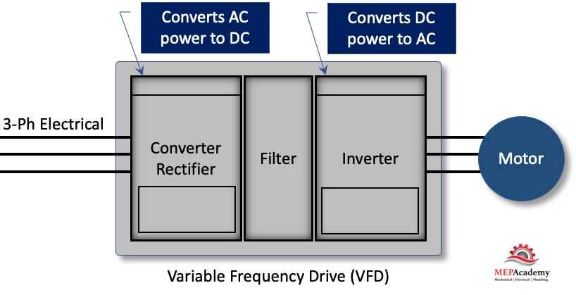
Converter (Rectifier)

The converter takes the incoming 3 phase Alternating Current (AC) power and converts into Direct Current (DC) power.

Filter

The filter smooths out and rectifies the DC voltage.

Inverter

The inverter rapidly switches the Direct Current (DC) on and off to create a pulsating voltage that mimics AC voltage. By controlling the rate of switching the frequency can simulate AC power applied to the motor to control its speed. So, basically switch from DC back to AC.

Controls Integration

The VFD’s have the ability to communicate over Ethernet with ModBus TCP or EtherNet/IP, also LonWorks, ModBus RS-485 interface and various other protocols. This gives your building automation or controls system the ability to monitor the status of various functions such as speed (RPM), Amperage (Amps), and any system faults or errors. 

There are options to add additional digital or analog input and output modules to expand on the ones provided with the base unit.

VFD Building Codes and Standards

Some standards such as California’s Title-24 building code require VFD’s on aal HVAC Fans and Pumps with a Horsepower (HP) greater than 10 Hp. Be sure to check with your local code jurisdiction for these requirements. Also, motors that are manufactured over 1 Hp are required to be compatible for variable frequency drives applications per the National Electrical Manufacturers Association (NEMA).

There are various other rules and regulations related to motors that are beyond this scope, such as the Department of Energy (DOE) Small Motor Rule, to 10 CFR Part 31 Energy Conservation Program (1/4 to 3 Hp), and guidelines established by the Energy Independence & Securities Act (EISA)(Minimum efficiencies for motors over 1 Hp).

Benefits of a VFD

Saves Energy

The main reason is to save energy by adjusting the speed of the motor to better match the varying load of the equipment. Motors consume a large portion of the energy used in buildings, so any improvement makes a big difference. Instead of running motors at full speed all the time, the use of VFD’s allows for saving energy when motor speeds can be reduced. This is also accomplished because a VFD won’t pull a high amperage draw like traditional motors rated for their Lock Rotor Amps (LRA), thereby saving the facility on electrical demand charges. 

Ease of Installation and Operation

Variable Frequency Drives are easy to install on a wall or mounted in a cabinet. The drives are very simple to operate and to adjust the speed or other settings.

VFD Rebates & Incentives

Check with your local utility company for rebates and with taxing authorities for tax incentives. The investment for the installation of VFD’s usually pays back in a short period of time. After the payback period the investment in VFD’s begins to provide an annual cost savings that increases net income for the business.

VFD Maintenance and Equipment Life

By avoiding the constant speed motors inherent need to cycle on and off to provide control of system requirements, you can extend the life of your equipment. The VFD provides for soft starts that provides better protection of the motor, belts, gears and wearing of the bearings. 

With a reduction in speed of a pump, there is a reduction in the forces within the pump casing which is carried by the pump bearings, so reducing speed increases bearing life. In addition, vibration and noise are reduced and seal life is increased, provided that the duty point remains within the allowable operating range.

With air-cooled VFD’s they need to be periodically inspected and their air-filters cleaned.

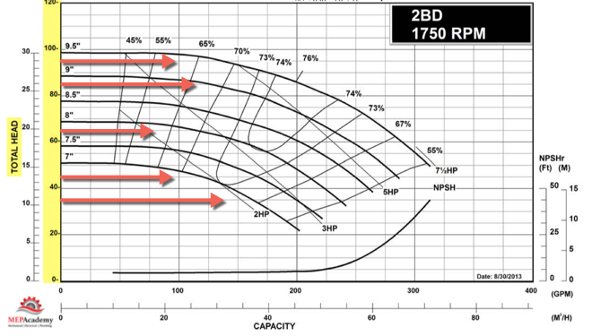
Motor Speed (RPM) – Affinity Laws

By adjusting the frequency (hertz) of the motor we can either slow down or speed up the fan, pump, or compressor. This is in direct relationship to the affinity laws where adjusting the speed (RPM) affects Flow (CFM or GPM), Pressure and Power. Checkout these video’s on Infinity Laws or this one on Variable Air Volume Systems using VFD’s.

Affinity Law #1 (Flow)

When adjustments are made to the speed of the motor, the flow is directionally proportional. So, if you cut the speed (RPM) in half, then you’ll cut the air or water flow (CFM, GPM) in half. A 50% reduction in speed is equivalent to a 50% reduction in flow. This applies to closed loop water systems.

CFM1 = CFM2 x (RPM1/RPM2) or GPM1 = GPM2 x (RPM1/RPM2)

Affinity Law #2 (Pressure)

The relationship of speed to pressure has a greater effect upon pressure when reducing the speed. For every adjustment in speed, there is a corresponding reduction in pressure to a quarter of what it was. So if you adjust the speed by 50% you get a 25% of the pressure

Pressure1 = Pressure2 x (RPM1/RPM2)2

Affinity Law #3 (Power)

This is where the greatest effect occurs when reducing the speed (RPM) using a VFD. When reducing the speed by half (50%) you’ll have power at one-eight. By reducing the speed of the motor attached to a fan, pump, or compressor you’ll save a greater proportion of power. The power is proportional to the shaft speed, cubed as shown in the formula below.

Power1 = Power2 x (RPM1/RPM2)3

Motor Starting Methods

There are various methods used to start motors with advantages and disadvantages for each. Using a Variable Frequency Drive provides for smooth starting and stopping.

The typical motor starter causes an inrush of current (amps) that is around 6 times higher than what is required when running the motor at full speed. The use of various soft start options still lack the ability for speed control of the motor. This is where the use of a Variable Frequency Drive provides for a soft start and the ability to control the speed of the motor for energy efficiency.

Other Names for Variable Frequency drives (VFD’s)

The following are various names used to describe the same thing as a VFD

  • Variable Speed Drives (VSD)
  • Adjustable Speed Drives (ASD)
  • Adjustable Frequency Drives (AFD)
  • Frequency Converters
  • Inverters

Summary

The use of a VFD will save energy and money, provide better control and reduce maintenance cost. The payback should be short depending on run time hours, utility cost and variable flow profile.

How Variable Frequency Drives VFD’s Work

How a Variable Air Volume VAV System Works

Variable Air Volume (VAV) is the most used HVAC system in commercial buildings. In this article we’ll discuss the Variable Air Volume system and single duct VAV boxes with reheat coils. The Air Handler varies the amount of air flow (CFM) at the overall system level based on the demand required by the zone level VAV boxes, which vary air flow based on their local demand.

To watch the Video of this presentation, scroll to the bottom.

The VAV box regulates the flow (CFM) to a zone in relationship to the demand of the temperature sensor in the space. 

Variable Air Volume System with VAV Boxes

Variable air volume is more energy efficient than constant volume flow because of the reduction in fan motor energy due to reducing fan speed (RPM) at partial load. As the cooling or heating demand is reduced because of a mild temperature day, the VAV Air Handler system can reduce the amount of air flow (CFM) by reducing the fan speed. 

Air Handler Unit with VFD

The air handler will deliver a constant temperature of 55ºF (13 ºC) supply air to the VAV boxes. While the supply air temperature stays constant the volume (CFM) of air will vary based on the total demand of all the zones on the system. There are several control strategies to adjust the speed of the fan which we’ll discuss below.

As the VAV boxes open or close due to demand called for by the temperature sensor in the space, the pressure in the main supply air duct will either increase or decrease. This pressure change is picked up by a static pressure sensor in the main supply air duct.

As the pressure increases in the main supply duct because the VAV boxes are closing their dampers and are adjusting their dampers towards the minimum open setting, the air handler supply fan VFD slows down the fan. The opposite will happen due to the VAV boxes opening because of increased demand and the dampers are opening, in this case the VFD will cause the supply fan to speed up when the pressure in the main supply air duct drops.

Duct Static Pressure Sensor controlling Supply Fan Speed
Duct Static Pressure Sensor controlling Supply Fan Speed (Sensor is located 2/3rds the distance down the main supply duct)

The VFD will try to maintain the speed (RPM) of the fan so that the static pressure in the duct at the location of the static pressure sensor maintains some minimum set-point, such as 1.25” sp. The static pressure sensor sends a signal to the VFD and the speed of the fan is adjusted according to the set-point required.

Basic Functions of a VAV Box

The VAV box at the zone level will operate in one of three modes: Cooling Mode that varies the flow rate (CFM) to meet a temperature setpoint; a Dead-Band Mode where the temperature setpoint is satisfied and the box is at minimum flow (CFM); and a Reheat Mode for when the space requires heat.

VAV Terminal Box Modes of Operation – One Strategy

As you can see in the diagram above the VAV Damper goes from a minimum of 30% open, whatever the minimum required to meet ASHRAE 62, all the way to the damper being 100% open.

There are basically three modes in this control strategy. Mode #1 Is the Cooling Mode where the heating hot water control valve is closed and the VAV damper modulates from 30% to 100% open in order to satisfy the temperature sensor. Next is Mode #2 Dead Band Mode is when there is no need for cooling or heating, so the damper stays in its minimum position to meet the ventilation requirements of ASHRAE 62. And Mode #3 is the Heating Mode where the VAV box damper remains in the minimum position and the heating hot water valves modulates open to satisfy the heating requirements of the space.

Function and Components of a VAV Box

The VAV box has a damper at its inlet moved by an actuator that is controlled by the controller that takes its command from a temperature sensor. The process is very simple. When the temperature sensor in the space calls for cooling it sends a command to the VAV box controller which then adjust the supply air flow rate (CFM). The adjustment is done by an actuator rotating the VAV box inlet damper either open or closed in increments.

  • Airflow Sensor – is used to adjust the damper position by measuring the air flow at the inlet of the box. The airflow sensor measures total pressure and static pressure to determine the Velocity Pressure which helps the controller determine the CFM through the inlet of the VAV box. Velocity Pressure = Total Pressure – Static Pressure.

Variable Air Volume VAV Terminal
  • Actuator – Based on the airflow the actuator will power the rotation of the damper to meet the space demand.
  • Damper – adjust airflow (CFM) based on the temperature sensor and airflow sensor input.
  • Reheat Coil – Depending on the zone, there may be a reheat coil that provides heating from heating hot water, steam or electric. The use of electric is limited in some jurisdiction due to energy codes.
  • VAV Box Controller – Taking input from the temperature sensor and the airflow sensor the controller will send and output signal to the damper or heating hot water valve to modulate open or closed. Controls can be pneumatic, electronic, or direct digital control (DDC). Pneumatic is an older form of control and is being replaced by the more energy efficient DDC system.
  • Other components used on various other versions of the VAV box, such as fan powered boxes would include fans and filters.

Zoning and Building Loads

Before we get any deeper into this subject we need to cover the basics of zoning. Zoning is how the Engineering divides up the building into separate VAV zones, with each zone getting its own VAV box. To keep cost down its best to limit the amount of VAV boxes used, as each box adds additional cost for material, labor, controls and electrical.

After a heating and cooling load is completed on a building, the spaces will be divided up into zones. Each individual zone will have similar load profiles and be served by the same VAV box. A typical individual zone maybe offices that share a southern glass exposure or interior spaces. Look for a Zone drawing in any set of mechanical plans that has a large area broken down into zones. (See example of a Zone Map Drawing below)

VAV Zone Drawing
VAV Zone Drawing

The idea of zoning is to breakdown large areas of a building into smaller zones with similar load profiles. When a zone on the south facing portion of a building is calling for maximum cooling, the north facing zones may be in minimum cooling or heating mode. Zoning allows different spaces the ability to provide cooling or heating and vary the flow (CFM) depending on the demand of that zone’s temperature sensor. 

All the zones on a floor of a high-rise maybe fed from the same air handler, but each zone can adjust its CFM according to their specific needs. Depending on the size of the floor plate, there maybe two Air Handlers per floor, or for smaller floors the Air Handler may feed more than one floor. The Air Handler can be located on the floor within a mechanical room or located on the roof. 

The supply air main is considered the high side of the system. The high side being the main supply duct from the air handler to the inlet of each VAV box. The main is considered upstream of the VAV box, while downstream of the box is considered the low-side supply.

The air handler will provide 55 F degree (13 Celsius) supply air to the VAV box. The Variable Air Volume VAV box will then determine how much air (CFM) to pass through to the space based on the demand of the space. The air handler is sized to meet the maximum block load of the area it serves. The block load is basically the peak heating or cooling load of all the zones combined. It is not the total CFM of all the peaks of each zone, but the total based on the worst month, day and time of year where the total block is at its maximum load.

Zone Map Example – VAV Dampers in Various Percentages of Open

Each zone above is reacting differently to the early morning sun. Some zones are in cooling mode with their dampers at different percentages of being open, while other zones are in heating and one zone is off and receiving minimum air for ventilation. This is a very basic diagram of how zones may differ and why it’s important to consider how spaces are grouped together, as each space may have a different solar exposure and cooling load profile. As the sun travels across the sky the zone dampers will open or close depending on their need for heating or cooling.

Corner spaces are often difficult to include with other spaces because they have two exposures. It’s like living on the corner in your block, you have two streets. Looking at the image we can see that there are two cooling zones between corner spaces that are on the south exposure that could be grouped into one zone, Zone #5 below. The same is true for the two zones between corner spaces on the North exposures, Zone #2. If you had interior zones they would be separated from any exterior zone because interior zones are often exclusively in cooling mode due to internal heat gains and the lack of heat loss from any exterior surfaces.

ossible Grouping of Spaces for VAV Zoning
Possible Grouping of Spaces for VAV Zoning

Cooling Mode

During cooling mode, the Variable Air Volume VAV box will modulate between a minimum CFM setpoint and the calculated design maximum cooling CFM setpoint based on the zones peak cooling demand. When the hot summer arrives and the sun shines through windows and conducts heat through the walls and roofs, the need for cooling will be sensed by the temperature sensors in the space which will call for the VAV box to open its damper and let more cold air into the room. Or, if you’re in a room located within the interior of the building, like a conference room, then the heat from the people, lights and plug loads will cause the temperature sensor to initiate an opening of the VAV box damper for more cold air.

VAV terminal Box with Reheat Coil – Maximum and Minimum CFM

Heating Mode

For exterior zones and in certain cases interior zones there will be a reheat coil or an electric heater attached to the VAV box The reheat coil can be served by heating hot water, steam or electric. When in heating mode, the flow (CFM) through the box will be at a minimum setpoint to avoid wasting energy. Remember that the air handler is sending the VAV box 55 F degree (13 Celsius) supply air which was most likely cooled by chilled water from a chiller

This primary supply air will also bring a percentage of mandatory ventilation air (Outside Air). In some systems the supply air temperature could be increased to a temperature that is just cool enough to cool the most-demanding zone with its VAV box set to maximum flow, thereby saving additional energy.

The heating hot water valve will modulate open providing a range of heating hot water flow (GPM) to meet the heating load. The minimum CFM setpoint can be somewhere between 30% and 50% of the maximum cooling setpoint. Minimums are set by some code jurisdiction so that the minimum ventilation rate is always achieved. In California see Title-24 Sec 120.1 Requirements for Ventilation and Indoor Air Quality. See Ventilation section next.

Using electric heat is not approved in various jurisdictions. Check your local code for approved sources for the heating requirements. 

Building Automation System

We’ll mention two control strategies for optimizing energy efficiency using a VAV system. These are the 1) Constant Static Pressure Control Method, and 2) Static Pressure Reset. (Required if there is a DDC system to the zone level)

When the VAV boxes are connected to a building automation system that monitors the function and status of the boxes there are various options for control. This is based on using a DDC system.

#1 Constant Static Pressure Control Method

Usually, a pressure sensor is installed 2/3 rds. of the way down the main supply air duct. When VAV boxes start closing their dampers because they need less cooling an increase in pressure will occur. When the static pressure in the supply duct increases due to the VAV boxes closing their inlet dampers the static pressure in the main supply air duct increases.

The pressure sensor in the duct will send a signal to the Variable Frequency Drive (VFD) causing the supply and return fans to slow down or reduce its RPM. If the pressure in the duct decreases because the VAV boxes are opening due to the need for additional cooling, the pressure sensor will send a signal to increase the fan speed (RPM). 

The pressure sensor is set to maintain a constant pressure in the main supply duct which often causes excess static pressure to be provided when compared to option two below. The reduction in the fan speed provides energy savings.

#2 Static Pressure Reset

The use of this strategy is required by Title-24 (California) and ASHRAE 90.1 for system that have DDC to the zone level. The static pressure setting in the main supply duct is reduced to a point where one VAV box damper is nearly full open. This is the zone that requires the most pressure. This would require that the VAV box actuators can report their damper position, best performed with an analog output. Look for Trim and Respond logic for more information. 

VFD Control using Static Pressure Reset

These options provide a good opportunity to save energy by reducing the fan speed and possibly increasing the supply air temperature in small increments with continuous polling. If the supply temperature can be reset above the economizer set point, then the compressors can stage off and the cooling can be provided by modulating the return air and outside air dampers to deliver the desired supply air temperature.

Using a DDC control system with VAV boxes that have a flow station and temperature sensor at the supply air discharge the system can determine the amount of reheat.

Q = CFM x 1.08 x Delta-T

Q = Btu/Hr

1.08 = A constant based on standard air conditions

Delta-T = (Discharge Air Temperature – Primary Supply Air Temperature)

The building automation system can track and trend over long periods of time the following: Damper position, static pressure, reheat valve position, airflow rate (CFM), supply air temperature, zone temperature and occupancy status.

There are other types of VAV boxes not discussed here such as: Fan Powered VAV Box, VAV Mixing Box (Dual Duct Systems), CAV (Constant Air Volume).

Ventilation ASHRAE 62

Ventilation air (Outside Air) is required for all occupied spaces according to ASHRAE standard 62.1. When using VAV boxes the minimum volume setting of the box needs to ensure the larger of the following:

1. 30 percent of the peak supply volume;
2. Either 0.4 cfm/sf or (0.002 m3/s per m2) of conditioned zone area; or
3. Minimum CFM (m3/s) to satisfy ASHRAE Standard 62 ventilation requirements. VAV terminal units must never be shut down to zero when the system is operating. Outside air requirements shall be maintained in accordance with the Multiple Spaces Method, Equation 6-1 of ASHRAE Standard 62 at all supply air flow conditions.

Summary

The use of Variable Air Volume (VAV) has been shown to save energy when combined with a supply fan VFD’s. As the demand in the spaces fluctuate the VAV box dampers open or close proportionately and the air handler fans respond through various control strategies. Variable air volume systems save more energy than a constant volume system.

How a Variable Volume VAV System Works

How to Read Pump Curves

The first two pieces of information that you’ll need to enter on a Pump Chart are the flow (GPM) and the pressure (Head). We’ll tell you how engineers get these two important pieces of information and explain all the curves you’ll find on a pump chart. First we’ll show you quickly all the different curves and lines, then for those who want further explanation we include that further in the article.

If you Prefer to Watch the Video, then scroll to the end of this article for the Video on How to Read Pump Curves.

Hydronic Pumps are used in the HVAC industry to move water that has either been heated or cooled to condition occupied spaces, or water for heat rejection equipment. There are various types of pumps used from end-suction pumps to inline-pumps using a variety of materials like cast iron, bronze, or stainless steel. Pumps can be secured in sizes for the smallest projects requiring a few GPM, to large projects requiring many pumps and thousands of GPM.

Pump Chart Basics

Reading a pump chart is very simple once you know the basics of what information to look for and what the charts are telling you. What you’re really looking at is a pump selection curve or pump impeller size curve. The pump curve is really the size of the impeller within the volute of that pump model. 

As the size of the impeller changes within the same volute and model number of the pump, there will be another pump curve for that impeller size with different performance results. The pump will always be performing at some point on this curve. Here are the curves of a pump chart that we will discuss later. 

  1. Pump Curve, also called Head Curve, Impeller Size Curve, Head/Flow Curve
  2. Flow (GPM)
  3. Head Pressure (TDH)
  4. Efficiency lines and (BEP)
  5. Horsepower Lines (HP)
  6. Variable Speed Curves (RPM) – Curve not shown on this chart
#1-Pump Curve, #2-Flow (GPM), #3-Head Pressure, #4-Efficiency (BEP), #5 Horsepower (HP)

With most charts you’ll have flow (GPM) on the “X” axis while Total Head Pressure will be on the “Y” axis with various other curves representing the HP (horsepower) of the motor, Efficiency, and impellor trim size. 

Each pump curve you see is related to a particular pump manufacture and model number. Every pump make and model will have a different pump curve which applies for a certain RPM and Impeller diameter.

The pump must move the quantity of water in Gallons per Minute (GPM) or Liters per Second (LPS) required by producing enough head pressure to overcome the resistance of the pipe, valves, fittings, components and coils within the system including the height the fluid most be moved.

The amount of water moved (GPM) or (LPS) is based on the speed of the pump, impeller size and head pressure.

Pump Curve, Head Curve, Impeller Size Curve, Head/Flow Curve

The Pump curve goes by various names. Looking at the Impeller lines we see that there are several different sizes, each with its own curve. This pump chart covers a certain make and model number which allows you to order different size impellers. It’s like ordering your favorite soda and having to choose the size of the cup, small, medium, large or big gulp.

Pump Impeller Size Curve

You can see from the chart above that you have the option of ordering this pump with the following sizes of impellers; 7”, 7-1/2”, 8”, 8-1/2”, 9” and 9-1/2”. This gives you plenty of options when selecting a pump. Now lets look at another set of lines.

Water Flow Rate (GPM)

The water is used to transfer heat either into or out of an occupied space or for a process. This is accomplished by various methods such as chilled water, heating hot water or Condenser Water. Each gallon of water carries various amounts of heat depending on its temperature. So, when we discuss pumps, we need to know how much water (Gallons) that needs to be moved to the equipment in a minute, hence GPM (Gallons per Minute), or LPS (Liters per Second).

Pump Curve Flow GPM
Pump Curve Flow GPM

As you can see on the pump chart above the flow (GPM) is represented by the vertical lines and the values are on the “X” axis along the bottom of the chart, highlighted in yellow.

Here is the formula for determining GPM. First you need to determine the heating or cooling load from doing a load calculation on the building and coming up with the required btu/hr needed at the peak for a particular zone being sized. Lets say our total tonnage for the building at peak load is 90 Tons and we’re designing with a 10F Delta-T.

Q = GPM x 500 x Delta-T or GPM = Q / 500 x Delta-T

Q = Btu/Hr

500 = Constant, 60min/hr x 8.33 lb/gal x Specific Gravity(1) x Specific Heat(1)

Delta-T = Design Temperature Difference in water

GPM = (90 ton x 12,000 btu/ton) / 500 x Delta-T

GPM = (1,080,000 Btu) / 5,000 = 216 GPM

Total Head Pressure

There are three terms of measurement in the total head of a fluid system: static pressure (gauge pressure), height (or potential energy), and velocity head (or kinetic energy). The head pressure of the pump is what gets the water to flow in the designed amount against the friction in the system and any static head.

Total Head Pressure Chart
Total Head Pressure

The lines for “Total Head” run horizontally across the chart depending on the head pressure from 0 to 120 feet for this chart. The head pressure values run on the “Y” axis along the left hand side of the chart. When selecting a pump you’ll use the GPM and Total Head as the starting points. But before we get to that lets explain the rest of the lines.

Efficiency lines and (BEP)

The efficiency lines or curves reflect the efficiency of the pump when operating in the ranges shown. The higher the value the more efficient the pump is at those conditions.

Pump Efficiency Lines - Best efficiency Point (BEP)
Pump Efficiency Lines – Best efficiency Point (BEP)

The greatest efficiencies are near the middle of the impeller curves. In this example you can see that 76% efficiency is the best this pump can do. This is the area you want to design for to achieve maximum energy efficiency. Efficiency runs from a low of 45% to a high of 76%. You never want to choose a pump that is far left or right of the Best Efficiency Point (BEP), which is in proximity to 76%.

Horsepower Lines (HP)

The horsepower lines indicate the size of the motor required to achieve the desired pump operation.

Pump Curve Horsepower (HP) Lines

The horsepower lines run diagonally across the chart and have the following four options for motor sizes. 2 Hp, 3 Hp, 5 Hp or 7-1/2 Hp.

Now that we have covered the basics lines and curves found on a pump chart we can dive into more detail for those who want to know more about each of these.

Performance Curve

This curve represents the pump manufacturer’s test results for where this pump will perform under varying conditions of water flow (GPM) and Head Pressure (Ft). These are the “X” and “Y” axis on the pump chart. If you change the GPM, then the performance curve will tell you what you’ll get in head pressure that corresponds that flow requirement.

Each pump make and model will have their own pump chart and pump curve showing where this performance curve is on the chart. The mechanical engineer’s job is to pick the right pump for the right conditions. Often the best place to select a pump is midpoint on the curve.

Characteristics of the Pump Curve

Looking at pump curves you’ll notice some to appear flatten out, while others have a larger arch to them. When selecting pumps for closed HVAC systems it’s best to pick pumps with flatter curves. Pumps that have flat curves allow for greater range of flow with less change in head pressure. Steep curves will have greater reduction in head pressure as you increase flow (GPM).

Pump Curve Characteristics - Flat Curve vs Steep Curve
Pump Curve Characteristics – Flat Curve vs Steep Curve

In a closed-circuit system, flat curves are preferrable because large changes in capacity will have a small impact on head pressure. The opposite is true of a steep pump curve, so that when you have a capacity increase you have a corresponding dramatic drop in head pressure. A flat pump curve provides for a more stable operation and control. You can understand how a flat curve is advantages when balancing multiple circuits, so that after each adjustment to one circuit there isn’t a major change in the other circuits.

Family of Pump Curves

Pump manufacturers use pump coverage maps to help you quickly identify which pump model best fits into your design parameter of flow and head pressure. As shown below using 180 GPM (681 Liters/Min) at 65 Feet (19.8 meters) of Head, the family of Pump Curves directs us to a particular model “2BD”. The overlap of some of these is due to various impeller sizes that are available for each model.

Family of Pumps - Quick Selection Chart
Family of Pumps – Quick Selection Chart

Pump Impeller Size

There are several options to get more out of one model of pump. One option is to change the size of the pump’s impeller. You’ll see several performance curves on the pump chart, one for each size of impeller available for that pump’s volute. By increasing the impellor size, the pump will provide greater flow (GPM). 

Pump Impeller
Pump Impeller

If your selection falls within two sizes, there is an option to have the impeller trimmed to fine tune the selection point. Trimming is often done to impellers of existing pumps possibly due to initially being over-sized which causes energy to be wasted by pumping more water then needed or adding resistance (Head Pressure) by throttling. The impeller is machined to reduce its size to closely fit the actual operating conditions.

System Curve

The system curve must intersect the pump curve for proper operation of the pump. The engineer will design the pump for a flow rate (GPM) and Head Pressure based on the pressure losses of a fixed HHW or CHW piping circuit. Any changes in flow will have a resulting change in pressure that follows this system curve. 

Pump System Curve
Pump System Curve

in the example above you can see that the system curve at its full operating capacity intersects the 9 inch impeller size curve giving a pump efficiency of approximately 75%, and a 5 Horsepower motor. This was derived from the system requirement of 205 GPM at 77 Feet of Head.

Reading Pump Gauges to Determine Head Pressure

From the suction and discharge gauge readings you can determine the feet of head at that current operating point. If the system is running at full load then this should give a good indication of the pumps head pressure capabilities. In the image below you can see that the suction pressure on the gauge is 90 psi, while the discharge pressure is 130 psi. Using some basic math we can convert psi into feet of head.

Converting Pump Pressure Gauge Readings into Feet of Head

The difference between the discharge and suction pressure gauge readings is 40 psi. To turn this into feet we need to use the conversion factor of 2.31 Ft/psi. By multiplying the differences in the gauges by 2.31 we get the head pressure of 92.4 Feet of Head.

You can use this pump differential pressure to derive at the pumps total head and then apply the results to the pump curve.

The Pressure of Water Converted from Feet to PSI

We measure this pressure in PSI (Pounds per Square Inch) or as Feet of Head. Their relationship is as follows: 1 PSI = 2.31 feet of Head.

Closed Loop Circuit

In a closed loop system the water moves around in a loop from supply to return and back. At no point does the water leave the system and become exposed to the atmosphere. Pumps that are used in closed loop systems, like chilled water, heating hot water, and closed loop condenser water systems, don’t usually need to worry about static pressure.

The reason static pressure is often not a factor is that the supply and return pipes run the same height, and one cancels out the other in static pressure. The predominate pressure loss in closed loop systems come from friction create by the flow (GPM) passing through pipes, valves, fittings and system components like coils.

Closed Piping System - Chilled Water
Closed Piping System – Chilled Water

Open Loop Head Pressure Calculation (CDW)

In an open system, the most common in the HVAC industry being the cooling tower condenser water. Condenser water is used to remove heat from the chillers condenser and reject this heat at the tower. The pump has to consider the difference in height between the supply and return water systems as they are not equal in vertical length. 

The vertical rise on the suction side of the pump goes to the cooling towers cold water basin water level, while the discharge side of the pump goes to the distribution nozzles or water outlet at the top of the cooling tower. The difference between these two levels will be added to the pumps head.

Open Piping System - Cooling Tower
Open Piping System – Cooling Tower

This is the indication of the pumps ability to overcome two things: 

  1. The vertical height of the piping including static lift if applicable
  2. Friction losses caused by friction in pipe, valves, and fittings.

The vertical height is determined by taking the difference in height between the water’s lowest and highest point in the system. Static lift is when the suction side of the pump has to pull liquid up from floors below.

The friction losses are determined by adding up all the friction lost from the pipe, valves, fittings and equipment. Friction loss is based on the type of pipe, size of pipe and the amount of water moving through the pipes. You will need to know the total length of pipe in the system per size including the equivalent length for fittings and accessories, along with the flow (GPM) going through the system.

Pump Chart with 180 GPM and 65 Ft Head

This chart shows the maximum efficiency occurring midway on the pump curve which is the ideal spot to pick the pump for efficiency for hydronic pumps. Making sure not to oversize the pump is crucial to avoid an energy penalty as reflected by the energy efficiency curves.

When selecting a closed loop pump be sure to select at the best efficiency point (BEP). This is the point on the pump curve where the pump operates at optimum efficiency for the impeller size, flow rate and head pressure for a particular pump model.

To the Operating Point or Non-Overloading

Pumps should be selected as non-overloading over the entire pump curve. This characteristic is most important for hydronic system operation, especially when pumps are to be used in parallel or when the pump operating point is relatively indeterminate and subject to shift; as in the normal heating-air conditioning application. – B&G

Net Positive Suction Head (NPSH) Curve

Net Positive Suction Head is mostly used when designing pumps for open systems like cooling tower pumps where they draw water from an open cold-water basin. The basin is open to the atmospheric pressure. If the tower is properly designed, then NPSH evaluation is not required. The pump requires NPSH to prevent cavitation and to operate properly. Cavitation will adversely affect pump efficiency and potentially damage the pump. 

Variable Frequency Drives

Systems that require variable flow will benefit from using Variable Frequency Drives (VFD’s) on their pump motors to save energy. As the demand of the system flow (GPM) is reduced so is the speed (RPM) of the pump motor which better matches the energy required at that time. This reduces energy consumption and avoids wasteful strategies like throttling or bypassing excessive flow.

VFD’s are common in large chilled water or heating hot water systems as there is often opportunities to slow down the pumps to meet the reduced load on the buildings cooling or heating system. As the building load varies, so to can the pump speed (RPM).  In systems with high static head there is a need to ensure that the pump doesn’t operate too slowly against the high-static head conditions. 

Horsepower is directly related to speed as dictated by the Pump Affinity Laws.

Bhp2 = Bhp1 x (rpm2 / rpm1)3

Pump Selection Criteria

In addition to flow (GPM), some of the decisions that the Mechanical Engineer will need to determine are:

  1. Is the pump to be installed in a closed or open system? 
  2. Will more than one pump be required? 
  3. Are the pumps to be constant or variable speed? 
  4. How will the pumps be arranged, in series or parallel configuration? 
  5. What is the design velocity of water in piping?
  6. Size the piping and determine friction rate per 100 feet of pipe.
  7. What is the pressure loss through the piping systems caused by friction from the pipe, valves, fittings, and other components, such as coils?
  8. Determine the circuit with the highest pressure drop.
  9. Does static lift or static pressure need to be included?

An open system occurs when using a cooling tower with a cold-water sump open to atmospheric pressure to reject the heat from a water-cooled chiller. A closed loop system is your typical heating hot water, chilled water system, or condenser water for water cooled equipment.

Pump Selection Software

To reduce the complexity of selecting pumps most manufacturers have developed software that will assist the engineer in selecting the right pump for the application. By entering the flow (GPM), head (FT), speed (RPM) and other fluid properties the software will generate a list of potential pumps that meet the entered criteria. You’ll then be able to view the various pump curves that match your selection.

https://www.esp-systemwize.com/pumps

How Electronic Expansion Valves Work 

The electronic expansion valve controls the precise amount of refrigerant that flows into the evaporator. This is based on the demand which causes a step motor to open or close the valve to achieve a certain superheat that avoids liquid refrigerant from entering the compressor.

You will find expansion valves in most refrigerant circuits from refrigeration and air conditioners to chillers. The need for increased accuracy, precise temperature control, better energy efficiency and remote monitoring has brought about an evolution in expansion valves. (See below for YouTube video on Electronic Expansion Valves)

Checkout these Electronic Expansion Values here

We will cover the main components including the superheat controller, electronic expansion valve, pressure transducer and temperature sensor, along with a brief explanation of superheat.

Refrigerant Circuit using a Superheat Controller

The expansion valve is one of the four main components found in refrigerant circuits. If you missed our video on Refrigerant Circuits you can find the link here.

All refrigerant circuits need a way to control the amount of refrigerant that can pass from the high side of the system to the low side. The refrigerant passes through the expansion valve in a liquid state. Once this refrigerant passes the expansion valve it ends up going through the evaporator where the liquid refrigerant absorbs heat from the air or water that passes over the evaporator. This causes the refrigerant to evaporate, going from a liquid to a gas.

Depending on the demand for cooling, the expansion valve acts to control the proper amount of refrigerant needed.

With the superheat controller monitoring the superheat and adjusting the expansion valve to maintain an optimally low superheat value that results in higher COP values. A higher COP translates into energy savings.

There are various manufactures and types of expansion valves and variations on how they function. We’ll cover some basics about the electronic expansion valve and some of the components that allow it to operate. First we’ll cover the various components that you’ll find in some of the electronic expansion valve setups and how they function.

What is Superheat

It’s all about maintaining the correct amount of superheat. Making sure you have a minimum amount of superheated refrigerant leaving the evaporator before it enters the compressors is important for the protection of the compressor and for accurate demand control. Compressors are not made to handle liquid refrigerant, so it’s important that only gas/vapor enters the compressor, otherwise you can damage the compressor. 

Superheat Controller

The superheat controller allows you to adjust the parameters and set which refrigerant is being used in the system. Each refrigerant has different characteristics of pressure, temperature and superheat values. 

Checkout these Electronic Expansion Values here

Using the two buttons on the superheat controller with the visual display is easy for technicians to make any setting required or view system states such as superheat, temperature sensor value and evaporating temperature. The display and its readouts will save the technician from having to retrieve service gauges and thermometers to determine these values.

Controlling superheat is an accurate method of ensuring that you have the proper amount of refrigerant, not too little or too much refrigerant, but an energy efficient amount to meet the demand. 

Superheat occurs when the refrigerant in the evaporator has completely evaporated into a gas and then additional heat is added to the gas. The initial heat caused the liquid refrigerant to turn into a gas. By adding additional heat after the refrigerant has completely changed into a gas the temperature of the refrigerant gas becomes superheated. 

Superheat = Temperature of Gas entering compressor – Boiling Point/Saturation point of refrigerant.

For example if your refrigerant boils at 40 degrees (4.4 C) in the evaporator, the point at which the refrigerant liquid turns into vapor, then adding more heat will cause the temperature of the vapor to rise, let’s say to 50 (10 C) degrees. This would give you 10 degrees (5.6 C) of superheat.

Typical control is based on superheat set point but an additional temperature sensor may be used to measure discharge water or air temperatures. This air or water temperature may be controlled directly, as long as superheat remains at a level sufficient to prevent floodback.

The job of the expansion valve is to make sure that the evaporator has the optimum amount of refrigerant injected into it no matter what the load or demand is at any time. This is done by using a Superheat Controller, Pressure Transmitter/Transducer and a Temperature Sensor with the electronic expansion valve to constantly sense the superheat in the evaporator. We will cover each of these components now.

Expansion Valve Superheat Controller

The Expansion Valve Superheat Controller calculates the superheat, after which it sends a signal to open or close the expansion valve opening to allow an accurate amount of refrigerant into the evaporator based on demand. 

Superheat Controller Manufacturers

This precisely controls the amount of refrigerant allowed through the valve based on the superheat of the refrigerant. The controller requires low voltage power and wired connections for the various input or output signals such as the pressure transducer, temperature sensor and or remote monitoring by the building automation system.

Alarm

The controller can send notification of any alarm set off by the system such as high or low superheat, bad pressure transducer or temperature sensor, minimum or maximum temperatures. This is done by the controller providing an error code on its LED display which corresponds with the manufactures trouble shooting literature to identify the problem area.

Hotkey

Look for the feature of a hotkey that allows you to program one controller and, than upload those setting to a hotkey where you can than easily transfer the settings to all other controllers needing the same settings by plugging the hotkey into all other controllers.

Superheat Controller

Remote Monitoring

This feature allows you to connect to your building automation system so that overview of the controller can be done remotely.

Battery Backup

If the system doesn’t have positive shutoff capabilities or use a solenoid valve to prevent refrigerant migration during non-operating periods such as during a power outage, then some means of power backup should be provided. That’s where this feature provides connectors for a battery backup or UPS (Uninterrupted Power Supply). 

Pressure Transducer

The pressure transducer or transmitter will provide the expansion valve controller with the current pressure at the discharge of the evaporator on the suction line to the compressor. 

Checkout these Refrigerant Sensors here
Pressure Transducer
Pressure Transducer

Temperature Sensor

The temperature sensor provides the other information needed by the electronic expansion valve controller in order to calculate the superheat of the refrigerant in the system. 

Checkout these Refrigerant Temperature Sensors here
Temperature Sensor
Temperature Sensor

With the temperature from the sensor and the pressure from the pressure transducer the controller can determine the superheat of the refrigerant and make an intelligent adjustment to the electronic expansion valve. 

Electronic Expansion Valve

The control of the amount of refrigerant flowing through the expansion valve is more accurate using an Electronic Expansion Valve EEV. This accuracy increases the efficiency and energy performance of the system by preventing wasteful amounts of refrigerant getting passed the expansion valve.

Electronic Expansion Valve Manufacturers

There are various manufacturers of EEV’s, such as Emerson, Danfoss, Sporlan or Carel, each with their respective benefits and features, but the premise is the same. The desire to control superheat to protect the compressor and provide an efficient amount of refrigerant is at the heart of the design of an expansion valve.

Some of the components of this particular electronic expansion valve are the #1 Permanent Magnet Motor and #2 Electric Coils that work together to adjust the #3 Needle Valve allowing #4 High Pressure Liquid Refrigerant to pass into the evaporator where it becomes #5 Low Pressure Liquid.

Electronic Expansion Valve (One View of Many Variations)
Electronic Expansion Valve (One View of Many types)

The step motor in electronic expansion valves doesn’t rotate continuously like your typical fan or pump motor. The step motor takes small steps in either direction to precisely control the amount of refrigerant going through the expansion valve. Baby steps in the tune of 200 to 400 steps per second, or a total of 2,500 steps to over 6,000 steps for larger models. One complete rotation could be 24 to 100 steps (15 to 3.6 degrees/each step) depending on the design of the valve.

Checkout these Electronic Expansion Values here

Sightglass

Parker’s Sloan Electronic Expansion Valve models SERI & SEHI have a built-in sightglass that can indicate the moisture level of the refrigerant, flash gas present upstream of the valve, and provides a visual confirmation of valve piston movement. This can be a useful feature for system refrigerant charging, service and diagnostics.

Checkout these Refrigerant Sight Glasses here
Sporlan Expansion Valve with Sightglass

Steps to Take when selecting an Electronic Expansion Valve

  • Determine Refrigerant to be used
  • Determine capacity required for the valve
  • Determine pressure drop across valve
  • Determine the liquid temperature of the refrigerant entering the valve
  • Select valve from the capacity tables of the valve manufacturer

Features and Benefits

  • Energy Savings
  • Accurate Control
  • Optimized Superheat Control
  • Optimally charged Evaporator
  • Precise Minimum Stable Superheat (MSS) Control
  • Improved Part Load for Variable Speed Systems
  • Works with all common Refrigerants
  • Intelligent Superheat algorithm with Safety Features
  •         * Compressor Protection
  •         * Fewer Compressor Breakdowns
  •          *Stable Operation 
  • Easy to Install
  • Controller works with a Modbus interface or as a stand-alone