Home Blog Page 54

Which Cooling Tower is best Crossflow or Counterflow

Cooling towers are used to remove heat from water used in water-cooled applications. The heat is rejected to the atmospheric air that is passed through the system fill in a crossflow or counterflow method. A small percentage of the hot water from the system evaporates, cooling the remaining water which falls into the cold-water basin which is then pumped from the cold water basin to the system to absorb more heat in a continuous process. 

It’s important to consider the efficiency of the cooling towers ability to reject heat for your project requirements. When you have the project requirements in the way of total tons, range and approach, then you can begin to analyze the cooling towers that would be appropriate for your water-cooled application. 

Crossflow and Counterflow Cooling Tower

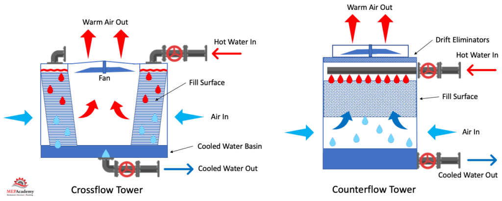
Induced draft crossflow and counterflow cooling towers both offer advantages and disadvantages based on specific project requirements and site conditions. 

The obvious difference is in the method by which the air moves through the cooling tower in relationship to the cooling water, which is indicated by its description of a being crossflow or counterflow.

With a crossflow tower the air travels horizontally perpendicular) to the water traveling vertically down to the cold basin. With a counterflow cooling tower, air travels in the opposite direction vertically upward against the stream of falling water.

Cooling Tower Footprint – Physical Size 

Air is required in sufficient amounts to accomplish the heat transfer requirements at the design conditions and at varying amounts for less than design conditions. Consideration must be made for this volume of air and the space required in the design of the tower to ensure the proper volume of air effectively interacts with the cooling water. 

Cooling Tower Footprint – Crossflow vs. Counterflow

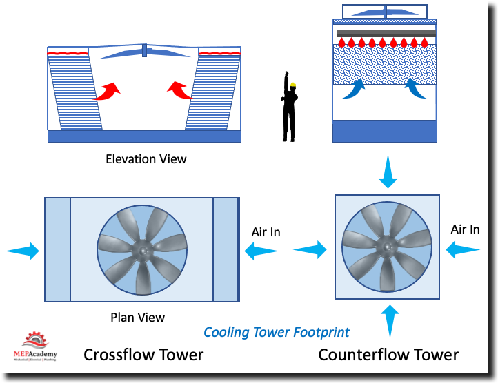
Cooling tower manufactures will have different footprint thresholds where the vertically configured counterflow goes from the smaller footprint to the larger footprint. Because of the nature of the counterflow tower where the air and water interact vertically, this allows for a smaller footprint most of the time in towers around 800 tons or less. As cooling towers get larger than 800 tons, the advantage could switch to counterflow.  

Site conditions will determine whether the physical size of the cooling towers footprint is more important, or any height restrictions imposed by site factors. 

Maintenance

In order to keep the cooling tower operating for efficiently and for its useful life it’s important to provide periodic maintenance. This will require that you consider tower access as a factor in the design and location of the tower. 

Crossflow Cooling Tower Maintenance and Access

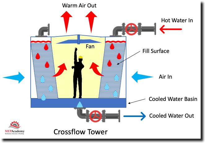
Access to the internal working parts various between the two designs. With the crossflow tower most of the internal parts are easily accessible as the fill material surrounds the exterior portions of the insides, allowing for access to the fan, motor, drift eliminators and cold-water basin. With larger crossflow cooling towers, the manufactures have an option to have ladders and platforms preinstalled for easy access to the motor and drive. 

Counterflow Cooling Tower Maintenance and Access

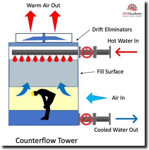
Access to the components of a counterflow tower are less friendly to the maintenance personnel because the overhead horizontal fill material provides a barrier between various components. The fan, motor, eliminators and spray system have limited access because they are located above the horizontal fill making then inaccessible from the cold-water basin.  

Cooling Tower Operating Weight

Because of the crossflow towers larger footprint, it’s shipping and operating weight will often be greater than that of the counterflow tower. The bigger footprint of the counterflow tower can require additional structural support legs. 

Water Distribution – Pressurized or Gravity

With the crossflow tower there is a hot-water basin above the fill that distributes the water that is pumped to the top of the tower. The water in the hot-water basin than makes its way through the distribution nozzles by gravity without the force of the pump. This allow for easier maintenance of the nozzles since the water is gravity fed and out of the air stream. 

The design of the counterflow tower and the method by which the water descends in direct opposition to the vertically induced air, necessitates the need to pressurize the water distribution. Since the water is under pressure through the nozzles this requires that you shutoff the pump in order to clean or service the distribution system. 

Another design and maintenance consideration are the method by which the water is distributed over the fill material. 

Cooling Tower Capacity and Energy Efficiency 

With many jurisdiction and states increasing energy efficiency requirements, the use of variable flow increases energy savings. As the tonnage requirement drops it’s wise to have the tower vary is flow in order to save energy. 

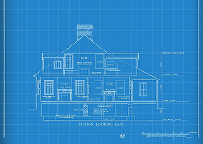
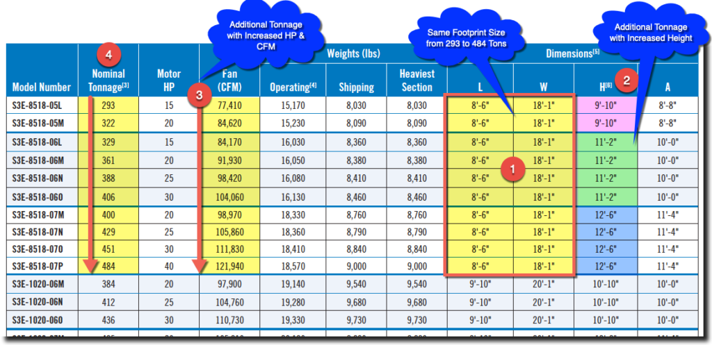
Capacity can be increased basically three different ways. One way is by increasing the footprint of the tower, the second method would be to increase its height, and the third way would be to increase the HP of the fan motor to get more CFM out of the same tower size before having to go to the next size tower. These are some of the decisions that will need to be made based on project conditions.

  • Increase Footprint (additional heat transfer surface area) #1 in image below
  • Increase Height (additional heat transfer surface area) # 2 in image below
  • Increase Fan HP (more CFM) #3 in image below
Cooling Tower Capacity vs Footprint, Height and HP (CFM)

Crossflow cooling towers are better at turndown than counterflow because of the inherent features of their water distribution methods. 

Cooling towers are rated based on standard conditions of 95ºF (35.0ºC) entering water temperature to an 85ºF (29.4ºC) leaving water temperature at a 78ºF (25.6ºC) entering wet-bulb temperature. This correlates to 3 GPM of water per nominal ton. For non-standard conditions seek the assistance of your local cooling tower sales representative and their access to tower sizing software.  

Cooling Tower Fill – Heat Transfer Surface

Cooling tower manufactures offer options on the type of fill based on factors such as the condition or chemistry of the water and the potential for biological growth. It’s important to prevent scaling which will reduce the capacity and ability of the tower to efficiently reject heat. 

The use of PVC for fill material is common due to its low cost and effectiveness in clean water applications. If the water quality is not satisfactory than the use of splash fill might be required which will also increase the cost due to it be less efficient at heat transfer, which will also increase the size of the tower to meet the same project requirements. The use of splash fill is less prone to clogging due to dirty water as opposed to PVC Film which can clog more easily. 

Cooling Tower Fans

There are anywhere from one or more fans that provide for the air movement through the towers. The most energy efficient being the axial fan which sits at the top of the tower. The use of centrifugal fans are more commonly used in forced draft fluid coolers. 

Summary

Your project requirements and site conditions will determine the best option of either a crossflow or counterflow cooling tower including any consideration for maintenance. 

HVAC Equipment Cost Database

Are you paying too much for your HVAC equipment? How do you know if the quote you received for your equipment is a fair price? Do you have a method of comparing what you have paid for various HVAC equipment with what is being quoted currently?

Keeping track of the cost of HVAC Equipment allows you to quickly provide budgets and check the cost of equipment before you purchase. This database allows you to easily keep track of the most common HVAC equipment.

HVAC Equipment Cost Database

Using an HVAC Equipment cost database will save you a lot of money by avoiding the costly mistake of paying too much for equipment.

Air Conditioners price per ton and price per square feet historical equipment pricing database
Air Conditioners in Historical Pricing HVAC Equipment Database

Get your copy here. HVAC Equipment Cost Database

The HVAC Equipment Cost database keeps track of all your equipment quotes or purchases for easy reference and parametric checks, such as cost per ton ($/Ton), cost per CFM ($/CFM)

Only $199

Construction Job Walk Basics 101

If the project is new construction, then there won’t be much to see except where the proposed building will be set on the lot and some of the logistics such as allowable lay-down area for materials and job site trailers/offices.

For retrofit projects of existing buildings there are some important aspects of the project walk that you will want to be sure to capture while your there if not already provided in the bid documents.

In order to get the most of your time when attending a project Job Walk you should get at least the following information.

Photo or Video of Existing Conditions and Equipment

Its important to take a lot of pictures of the area and equipment that is affected by the renovation. You’ll use these photos or videos back at the office during your review so that you can share what you saw with the team involved with assembling the bid. Often, you’ll see something in the photo that you didn’t notice during the job walk which the photos and videos allow you to review at a more relax environment.

Equipment Labels
Equipment Labels
  1. Equipment Labels
    • Make sure to get a good picture of all the existing equipment that needs to be remove or replaced.
    • Take a picture of the equipment labels that identify the make and model number of the piece of equipment plus all the additional capacity information listed.
    • Get a picture of the electrical panel that serves the existing, including the inside list of breakers. The photo will also show which breakers are being used and also which are in the off position.
  2. 360 Degree View of Area and Equipment
    • Take a picture on all four sides of any equipment or area involved in the renovation. This is important so that you can review any side of the equipment back at the office.
  3. Auxiliary Equipment and Accessories
    • Make sure to get pictures of any ancillary equipment that is part of the renovation, such as expansion tanks, plumbing fixtures or electrical.
    • Electrical panels related to the work if new circuits are required or are to be upgraded.
    • Control panels or controllers that need to be replaced or upgraded.
  4. Panoramic Views
    • Step back from the actual equipment as much as makes sense to get a good overall photo of the area of work. Sometimes those walking the project will get good closeup pictures of the equipment but won’t give an overall view of the total area. It’s easy to zoom in on a long shot picture, but that’s impossible with one that is already shot up close.
Job Walk Basics Panoramic Photo
Job Walk Basics Panoramic Photo – Step Back and Take a Picture from a distance
  • 5) Similar Equipment
    • Often the project may require you to replace equipment that looks the same, such as replacing all the rooftop Air Conditioners. In this case in order to keep your photos organized as to which photo belongs to which AC unit, you’ll need some way to identify each.
    • If there are equipment tags on each unit, then take a picture of the tag first and then another for each side of the AC unit or similar equipment before moving onto the next. If there are no equipment tags, then you can make your own by writing on a piece of paper the Equipment Tag, such as AC-1, then taking a photo of your written tag, then each side of the AC unit.

Dimensions of Important Items

The following are some of the items to thing about getting dimensions of while you’re onsite.

  1. Equipment pads or platforms
    • Dimensions of concrete pads or platforms where the new equipment will sit.
  2. Rigging Pathway
    • If you are moving old equipment out and new equipment in, then you will need to measure hallways and doorways along the path from the room where the equipment is located to where it enters the building.

Make sure to get all the pertinent photos of the equipment or work area that is part of the contract. For retrofit projects

As-built Drawings (Existing Drawings)

If doing a renovation or a design/build project it’s a good idea to ask the owner, facility engineer or there representative if they have copies of the existing MEP drawings. This can make your job a lot easier if you need to redesign the system.

Existing As-built Drawings

Also, any Architectural or Structural drawings can be useful especially if your replacing equipment on the roof. If the new equipment is heavier or if the structural code has gotten more stringent from the time the building was designed and built, then you might need to submit a structural review in order to confirm that the existing structure can hold the weight of the new equipment.

It best to get these in electronic format or to take pictures of the existing drawings if not available digitally.

Tools to Bring on your Job Walks

Personal Protective Equipment (PPE)
  1. Some form of measuring tape, whether digital or hand held.
  2. PPE Equipment. Some sites require that you bring a Hard Hat, Goggles, Fire Retardant Clothing, Safety Shoes/Boots/Vest, etc. You should always keep a set of PPE in your car, so that you are always prepared for a site walk. Even if it’s not required, it’s smart to wear protective clothing as some equipment rooms contain sharp edges and job site conditions could contain slippery or dirty surfaces.
  3. Cell phone or camera to take pictures and videos.
  4. iPad or note pad for taking notes and writing down dimensions and making sketches.
  5. Flashlight to see dark areas in mechanical rooms, attics or within equipment.
  6. A copy of the construction drawings and scope of work.

Bring Important Subcontractors & Vendor

If you are bidding on a turn key project, one where you are responsible for all of the other trades. This often occurs when the majority of the work is related to the mechanical, such as the replacement of major HVAC or Electrical equipment upgrades.

It’s also most likely that your company specializes in one of the MEP trades and will need to provide another subcontractor to do the other portions of the work. You might be an HVAC contractor that is comfortable replacing the mechanical equipment, but not in upgrading the electrical panels. It’s also possible that quite a bit of new structural work will be required to support the new equipment.

Maybe you want to bring out the manufactures representative of the major equipment that is being replaced. Be prepared to bring your team members that will be involved in providing you with the quotations you’ll need to provide a complete proposal. This is especially important on Design/Build projects where you are responsible to provide a complete and operable system per the intent of the RFP. This is also important in renovation so that your team can assess the existing conditions in order to apply reasonable labor factors.

Sheet Metal Takeoff – Test 3

In the next two test you will be required to measure the lengths of the ductwork using the bar scale shown on each drawing. Print the enclosed drawings or use a distance measuring software program like Bluebeam so that you can accurately measure the distances for each duct length based on the bar scale shown on the drawings, or if you have an estimating program you can import the drawing and do your takeoff.

Another method is to measure the drawing on your computer screen, which can be done by increasing the magnification of the drawing until the bar scale on the drawing matches the hand held scale you hold up to the computer screen.

In the following series of test there will be no numbered items given. It will be up to you to determine what you need. Start as always at the source or the largest duct in this case we have outlined the path to take for you, so that the answer sheet given will follow the same path. Start at the letter “A” on the diagram and proceed in alphabetical order until you finish filling in the takeoff form.

Make sure that you have completed all the practice test, including Test 1 & 2 before proceeding.

Download the PDF Drawing and Takeoff form or use your own tablet or computer to record your answers that match the list for each of the following takeoffs.

Write down a description of the duct or fitting along with the appropriate size shown. After you have completed your takeoff, check your answers with the online answer sheet. Don’t worry if the lengths are slightly different. The lengths should be close, at least within 6” or so, depending on your method of measuring.

Air Conditioning Unit Ductwork #1

Air Conditioning Ductwork #1 - Test #3
Air Conditioning Ductwork #1 – Test #3

Fill in the PDF Takeoff Form with answers to Air Conditioning Unit Ductwork #1 Image Above.

VAV High/Low & Exhaust Ductwork – Takeoff #2

Start with the High-Side Supply Mains, then the branches to VAV-1 & 2, followed by the Low Side Supply and then finish with the Exhaust ductwork. Do your best to identify every piece of duct or fitting. Be sure to follow your takeoff as shown starting at the letter “A” and progressing to “B”, then to “C”,, “D”, etc. Make sure to takeoff all the duct and fittings shown for each letter in alphabetical order so that the answer sheet will make more sense to you.

In this exercise you will be required to provide the duct lengths, so be sure to download the drawing and confirm your scale using the bar scale on the drawing before proceeding. If for some reason you can’t measure the ductwork, then proceed as in previous exercises by just indicating a section of ductwork without the length.

Download the PDF Takeoff Form if you haven’t already or use your own tablet or computer to record your answers.

VAV high / Low Side and Exhaust Ductwork #2 - Test #3
VAV high / Low Side and Exhaust Ductwork #2 – Test #3

Resources

PDF Takeoff Form

Test 3 Drawings

Answers to Test #3

Additional Sheet Metal Takeoff Chapters