Fill out the list below from 1 to 30 that corresponds to the numbers on the below image, and then write down a description of the duct or fitting along with the appropriate size if shown. See if you can get 100% of the pieces correct. After you have completed your takeoff, check your answers with the online answer sheet. You can also download the PDF Takeoff Form here.
VAV Sheet Metal Practice Test 1
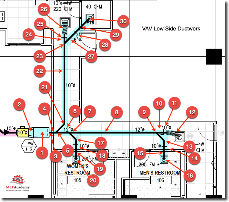
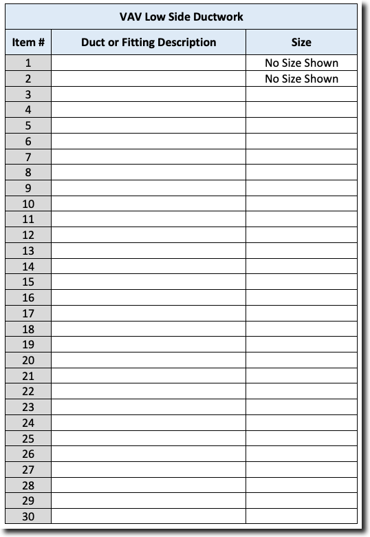
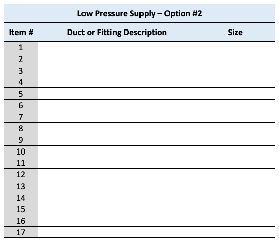
Fill in Table below with answers to VAV Low Pressure Ductwork Image Above. Don’t include any Air Distribution Grilles, just ductwork, fittings and duct accessories.
You can also download a PDF version of the takeoff sheet here.
Sheet Metal Practice Test #1 – Blank Form
Below is a copy of the answer sheet for Practice Test #1 and the following test.
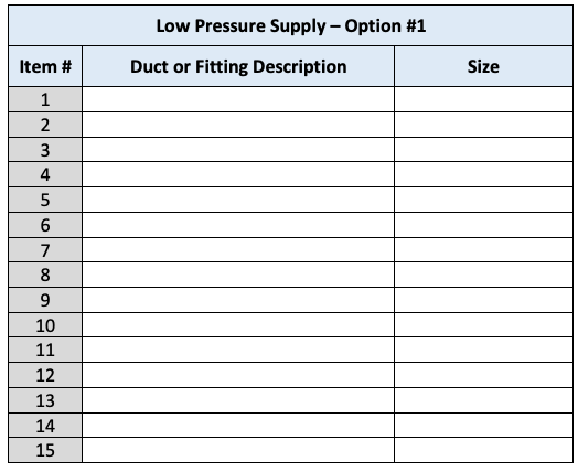
Low Pressure Supply – Option #1
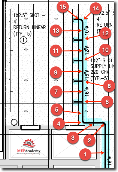
Below is another round supply duct practice takeoff for you to get comfortable recognizing how different engineers represent the various fittings that are not defined. There are several options available to you with this takeoff depending on what the engineer allows in the specifications. We will provide several optional answers. Don’t worry about the lengths of ducts, just indicate that there is a section of duct required.
Round Sheet Metal Takeoff Practice Test
Fill in table below for each of the numbered items shown in this image along with the description of the duct or fitting along with its size. Don’t worry about the lengths of duct at this time, just indicate if it’s a section of duct or the type of fitting.
After completing the sheet metal takeoff check your answers online with the corresponding answer sheet for this practice test.
Sheet Metal – Low Pressure Supply Test Option 1
We didn’t ask you to finish all the individual branches, but in this case there would be short stubs of 10” duct to each linear diffuser. What is missing from this engineered drawing is the volume damper for each linear diffuser but don’t worry about that now, just remember to add one in a real estimate as they are required to balance the air to each linear diffuser.
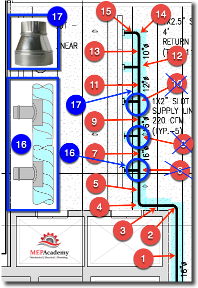
Low Pressure Supply – Option 2
We added an optional method of estimating the previous image as shown below with our modifications. Fittings #6, #8 and #10 will be eliminated and #16 will be added in their place, including item #17. Can you identify the newly added fittings #16 & 17?
Sheet Metal – Low Pressure Supply – Option 2Sheet Metal – Low Pressure Supply Duct – Option #2
If you have a computer estimating program with the capability of onscreen take-off, then this course will give you a good understanding of what is required in order to understand the parts and pieces that go into a computer estimating system.
Being able to do a take-off by hand will give you a better understanding of all that goes into the automation of a computer program. Having a computer estimating program is required for any company wanting to bid plan and specification projects as opposed to a retrofit job.
Computer estimating speeds up computation and provides a faster method for doing take-offs and updating prices and a host of other advantages. The following process and procedures for doing a take-off is described from the point of doing a manual non-computerized take-off, but is applicable to understanding what goes into an estimating software program.
Sheet Metal Takeoff
We will cover the steps needed in order to do an accurate and thorough takeoff of the sheet metal. Now that you have learned how to recognize round and rectangular ductwork, fittings and specialties, we will learn a few variations or options you might have if the drawings and specification are not clear on which type of fitting to use.
It is best to always start at the source of the air, such as the air conditioner or fan and work your way to the last air outlet or inlet grille. In the case of a VAV system with high side and low side ductwork you can begin at the shaft where the main ductwork comes from the air handler as shown below, or if floor mounted Air Handlers are used, you can start in the mechanical room with the sheet metal connection to the Air handler
Choosing your Fittings and Branch Connection
What are your choices when you arrive at a branch that is perpendicular to the main run? The most aerodynamically efficient fitting choice is shown below which includes two transitions and a 90-degree elbow, note that a radius elbow could also be used. This is also the most costly choice, because of the number of fittings that has to be fabricated in the shop. There are 3 fittings to fabricate (2) transitions & (1) 90-degree elbow.
Duct Split-Option
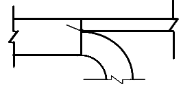
Another less costly alternative as shown below would be to provide one branch to continue forward, and the other would have a 90 radius elbow. Obviously this alternative has fewer fittings and as such will be less labor intensive, and less expensive to fabricate.
The assumption in the arrangement below is that the small duct that continues straight ahead will have the same depth as the main because no transition is indicated to change size. They both accomplish the same thing, but with different approaches. There is only one fitting; (1) 90-degree radius elbow, as opposed to three fittings in the above scenario.
90-Degree Radius Elbow
Assuming that the duct size would need to be reduced according to the duct sizing requirements, then a transition after the branch tap would be needed to resize the duct for the remaining CFM (cubic feet per minute).
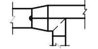
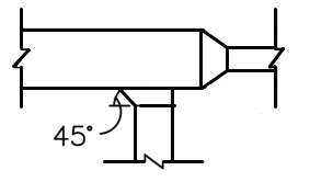
The third option below uses a 45-degree tap-in fitting for the branch connection, and a transition for the straight run. In this arrangement there are only two shop fabricated fittings; (1) transition and (1) 45-degree tap.
45-Degree Tap Branch Connection
If the plans and specifications don’t indicate which method is the preferred or required, then it becomes a company decision, based on your company’s construction standards. If the engineer doesn’t limit your choice of fittings, then you have to make the decision as to which fittings to use in the above scenarios.
You can go with the least expensive option or the most energy efficient which is the more costly alternative. Make sure to read the specifications and look for any drawing details that show how you must make sheet metal branch connections.
Duct Offsets Up or Down
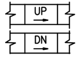
The symbol below indicates that the duct is rising up or down in the direction of the arrow. Ducts that indicate they’re going up (UP) will increase their bottom elevation, while ducts that indicate they’re going down (DN) will decrease the bottom elevation of the duct.
Duct Offsets
VAV / CAV Terminal Box Connection
When contracting commercial construction projects it is common to find some form of Terminal box controlling air volume into the space. These VAV (Variable Air Volume) or CAV (Constant Air Volume) terminals will have a piece of duct coming off the front, or a Manufacture/Contractor provided lined plenum. This connection to the terminal box is often defined by the engineer or shown on the detail page of the design drawings. There are several choices shown below.
VAV / CAV Plenum
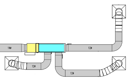
Often the engineer will require a lined plenum be attached to the VAV box. This helps with sound attenuation. It’s also possible that no taps or connections will be allowed on the sides of the plenum, and that you would need to make all connections after the plenum. The plenum is shown in blue below.
VAV / CAV with Lined Plenum
VAV /CAV Square to Round
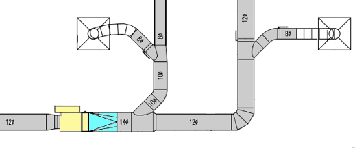
One of the most economical ways of connecting to a VAV terminal is to immediately start with a Square to Round fitting. This is because most contractors find it less expensive to purchase and install round duct as compared to rectangular, so they want to transition immediately.
VAV / CAV with Square to Round Fitting
Rectangular Duct Takeoff
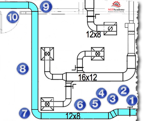
The best way to learn how to do a sheet metal take off is to jump in and try for yourself. But before you do, we’ll show you several audit trails of sample takeoffs. Just follow the number sequence of the audit trail and see if you can identify the duct, fittings or accessories as we have shown them below starting with number 1.
That was pretty simple as each piece didn’t need much interpretation because of their easily recognizable shape and symbol. It gets a little more difficult as we go along and the experience of a trained eye will pick up the items that aren’t shown but required.
Rooftop Packaged Unit – Down Shot with Supply Ductwork Shown Highlighted
Audit Trail #2 (Packaged A/C Unit on Roof)
Equipment Flex Conn. 26” x 24”
Riser Duct 26” x 24”
Elbow – 90 Degree 26” x 24”
Duct 26” x 24”
Elbow – 90 Degree 26” x 24”
Duct Section 26” x 24”
Transition 26” x 24” to 20” x 16”
Duct Section 20” x 16”
Elbow – 90 Degree 20” x 16”
Duct Section 20” x 16”
Transition 20” x 16” to 14” x 8”
Duct Section 14” x 8”
End Cap 14” x 8”
Rectangular Tap 18” x 16”
Duct Section 18” x 16”
The audit trail starts with the vertical connection to the Air Conditioner using a (#1) Equipment Flexible Connector, then (#2) Riser Duct Section, followed by a 90-degree elbow or an end cap to form a plenum. There is a good chance that you might have a transition from the size of the connection at the equipment to the size that you want to run the main duct size.
Often the engineer won’t provide an elevation view that shows how far the duct drops vertically from the Air Conditioner or Air Handler above, so you’ll need to estimate the approximate vertical distance based on the floor to floor height and the ceiling height in that area. Items #1 and #2 above aren’t shown on the drawings but are inferred by the drawings and notes.
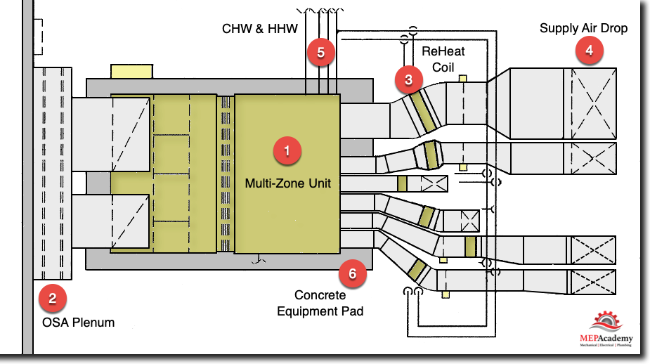
Multi-Zone Units
A Multi-Zone Unit (#1) has multiple supply air ducts coming off the unit feeding individual zones. Instead of one main supply air duct coming off the AC unit, these units have multiple supply air ducts. As can be seen in the drawing below, the first item of sheet metal attached to this multi-zone unit is the flexible duct connectors. You would start with the first zone and then continue until you completed each of the zones on this unit.
Most of what you will find on each of these sheet metal duct runs is a Flexible connector at the unit, straight duct sections, angles, transitions, Reheat coils (#3), Volume Control Dampers and 90-degree elbows (#4).
This Multi-Zone Unit (#1) provides 100% Outside Air through a Louver and OSA Plenum (#2) at the exterior wall. Its normal for units to sit on a concrete housekeeping pad (#6). The Multi-Zone unit is fed with CHW (Chilled Water) & HHW (Heating Hot Water) piping (#5).
Multi-Zone Unit with Sheet Metal shown in light grey
This particular multi-zone air handler is for a hospital so it has 100% outside air and NO return air. The outside air can be seen rising off the top of the back portion of the multi-zone unit and then turning with the use of a 90-degree elbow where it then taps into the back of a plenum attached to an Outside Air Louver.
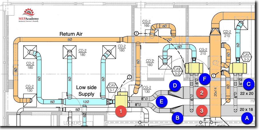
Double Duct System
The Double Duct System is another variation of duct configurations you will see when bidding on commercial projects. This system uses two mains supply air ducts, one for the cold air and another for the heated air. As shown in the image below the system uses double-duct mixing boxes (#1) which is fed by a main COLD Supply (#2) and HOT Supply (#3) duct main, to control the temperature set point.
Double-Duct System
With this system you’ll want to separate the high side from the low side ductwork. The demarcation or separation between the high and low side is determined by the location of the double duct mixing box. Everything before the box is considered the high side; this would include the main cooling and heating supply air mains that feed each mixing box. Everything after the box is considered the low side; this would include the flexible duct connectors to the air distribution diffusers.
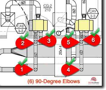
Did you find the (6) 90-Degree Elbows for item “F” in the image above? If not, look again and then check the image at the end of this course for the actual count.
The reason to keep the various high and low pressures duct takeoff’s separate is twofold, first the pressure classification or static pressure at which the duct will be fabricated differs, and secondly, the labor for the different duct systems will be different, as the main ducts and fittings are larger, while the low side ductwork is much smaller.
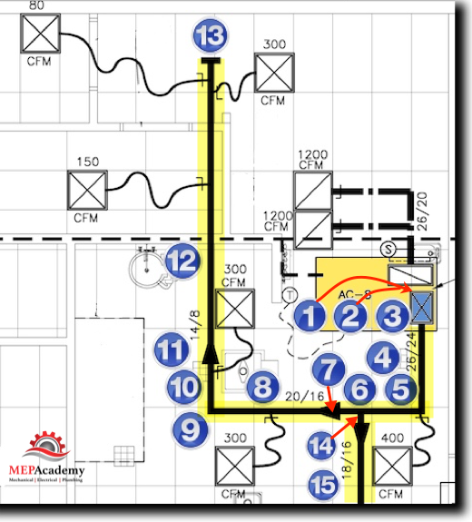
VAV high Side Ductwork & Page Break
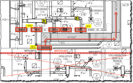
When floor plates or the size of a building floor plan is too large to fit on a single page the engineer will show a Match Line (#1) where you can conveniently stop your takeoff on one page and begin on another. The dotted line (#1) running horizontally across the page in the below image matches with the dotted match line (#5) shown on the other drawing below.
Match line between drawings
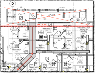
Your takeoff for this drawing should start and stop at this match line or a significant break point such as the SFD (Smoke Fire Damper) (#4) so that you don’t accidentally double up on your takeoff. This is a VAV system with both the High and Low Supply Air portions shown. This is where you will keep the two separate when you do your takeoff. In the image above you will NOT takeoff anything in the hatched out area (#2), or (#6) below as they belong to the other drawing. Item (#3) above and (#7) below are the direction in which your takeoff will proceed.
Match Line – Matching Other Section
You can see that the match line of the second drawing above matches that of the first one except for the direction in which the new work is shown.
Mechanical Rooms and Elevation/Section Views
It is often difficult to distinguish what fittings or lengths of ducts are required in mechanical rooms and crowded areas. Without an elevation/section view you would need to make an educated guess about vertical distances and fittings, especially if there were no Architectural plans to inform you of the heights and restrictive building elements.
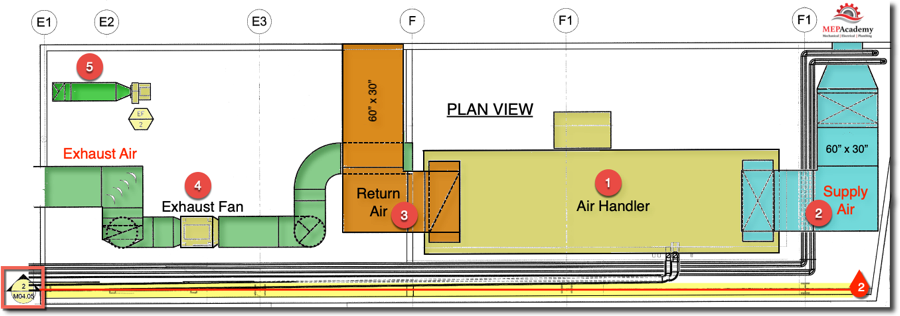
Plan View of a Mechanical Room
The plan view of the Supply (#2), Return (#3) and Exhaust (#4) systems show that the ductwork rises from the equipment, but there is no way to tell how much straight duct there is on the riser without a section view (shown below). Looking at the section view below you can measure the distance with your computer program or use a scale to get the exact length because it is drawn to a 1/4”= 1’-0” scale. Without an elevation view you would have to make an educated guess as to how much of a vertical rise the duct makes.
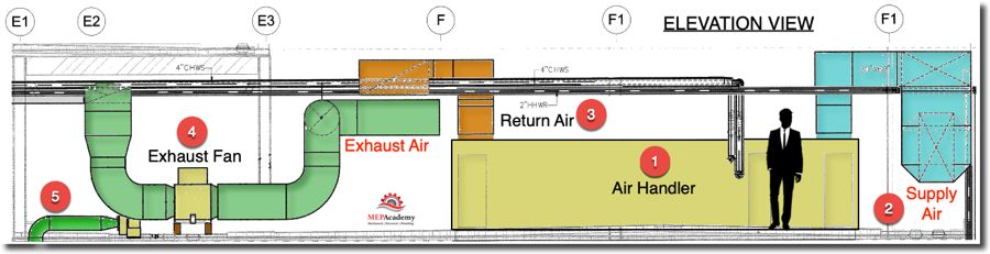
Elevation View of Mechanical Room above
If you have submittals (Physical & Dimensional data) of the Air Handler (#1) and exhaust Fan (#4) and the Architectural drawings, than you can determine an approximate height that will be good enough for estimating purposes. As you can see in this elevation view there isn’t that much of a vertical rise in any of the three systems. The Return Air (#3) and Supply Air (#2) ductwork have short stubs of duct before they turn using an elbow.
Answer to Double-Duct Question above
Answer to Question above on Double Duct Systems
There are six elbows. There is one elbow (#1) after the starting collar coming off the main duct, then the 6” duct turns vertically down (#2) and then turns again (#3) immediately turning horizontally into the double duct mixing box. There are three elbows on one main branch connection from the Main Heating Duct to each Double-Duct box, the other main branch goes straight into the box from the side of the Main Cold Duct without any elbows.
We’re going to cover how to Calculate GPM of a new Chiller Evaporator or Condenser Coil or any New Coil or Heat Exchanger by a field measurement of the pressure drop compared to the rated pressure drop of the equipment.
If you prefer to watch a video on this topic, scroll to the bottom of this page for link.
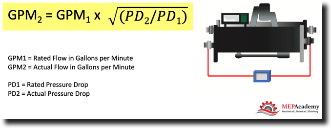
In this equation GPM2 is the actual flow rate that we’re going to calculate, it could be for any coil whether in a chiller, fan coil or heat exchanger.
How to Calculate Flow (GPM) in a Coil
So the Rated GPM is GPM1, times the square root of PD2, which is the actual pressure drop that we are going to measure. This is different than the Rated Pressure drop, which is PD1, the pressure drop across the Chiller’s Evaporator, Condenser or Heat Exchanger that your trying to measure.
So what will happen to the GPM if the Pressure Drop (PD) increases or decreases?
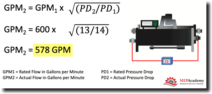
For our example we’re going to take a new chiller that was Rated for 600 GPM at 14 feet of Pressure drop through the Evaporator.
Measuring Flow Across a Coil
When we go into the field and measure the actual pressure drop we get 13 Feet.
Field Measurement Confirming an Actual Pressure Drop of 13′ vs the Rated Value of 14′
Now what we are going to do is we’re going to take all the known Rated conditions of the new piece of equipment, in this example the evaporator of a chiller and the actual measured pressure drop from our field technician.
So here is our formula. All we’re going to do is put in the known Rated values for the evaporator. Which GPM1, the Rated GPM is 600, times the square root of the actual measured pressure drop, which came out to 13 feet divided by the rated pressure drop (PD) of 14 feet for our example evaporator.
All it is at this point is math. So, doing the math we come up to 578. So our 600 GPM at 14 feet pressure drop Rated condition is now only flowing 578 GPM due to the decrease in pressure drop.
How to Calculate Pressure Drop in a Chiller or Coil
So a decrease in pressure equals a decrease in GPM.
The refrigeration cycle is the heart of the HVACR industry. Just like the heart in the human body which circulates life giving blood, the refrigeration cycle circulates refrigerant using a compressor. Before we explain the refrigeration cycle we need to explain a few principles of physics to help you better understand and retain the information.
Moving Heat
The purpose of the Air Conditioner or Refrigerator is to MOVE heat from one space to another. In the case of an Air Conditioner, you want to move the heat out of the building. Those in the HVACR industry are professional movers of Heat, either by moving heat out of a building or bringing heat into a building. One of the ways to do this is with the refrigeration cycle.
Heat is either moved out of or into a Building
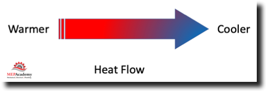
Heat Flow
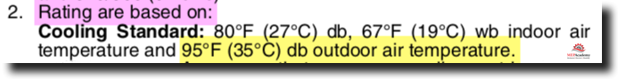
Heat flows from the warmer medium to the cooler medium. So for the condenser to reject its heat to the outdoors using an air-cooled condenser the temperature of the condenser has to be greater than the surrounding outdoor air. This is why during really hot summer days when the temperature is above the temperature rating of the condenser, which is usually rated for 95 Degrees, the cooling capacity is reduced.
Heat Flows from Warmer to Cooler Mediums
The greater the outdoor summer temperature above 95 degrees the worse your air conditioner will operate as it makes it difficult for the condenser to transfer its heat to the outdoors when the temperature difference is reduced.
See the notice located in the Air Conditioners manufactures literature for the performance of the Air Conditioners rating as shown below, the outdoor temperature is figured to be 95 degrees. Which means anything above that will reduce the tonnage (reduce cooling) of the AC Unit.
Temperature Rating of Condenser
Heat seeks to equalize with the medium around it by transferring some of it heat to the cooler medium until they equalize. You can’t transfer heat to something that is warmer, only something cooler.
Temperature and Pressure Relationship
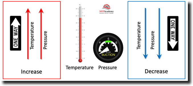
To understand the compressor, you’ll need to understand the relationship between Temperature & Pressure. It’s very simple as they act in the same direction in the refrigeration cycle. If you increase the pressure than the temperature also increases. If you decrease the pressure the temperature also decreases. Pressure and Temperature move in the same direction like a one-way highway.
Temperature – Pressure Relationship in Refrigeration Cycle
In the refrigerant cycle we have the LOW & HIGH pressure sides. The high side is shown in red, while the low side is shown in blue in the following pictures. There are two sides, like in martial arts or Tennis. You have the Low Side & the High Side which is created by the compressor.
Phases of Refrigerant
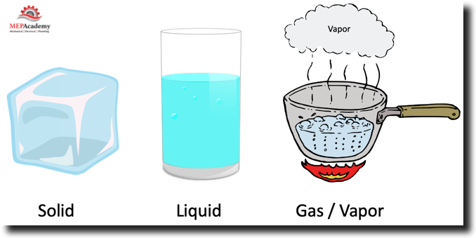
Now we need to know what phases the refrigerant is found in within the system. You’re familiar with water so we’ll use that as our initial example. Water basically has three phases that it can be found in as follows;
Solid: Ice
Liquid: Water
Gas: Vapor, Steam
Phases of Water – Solid, Liquid and Gas
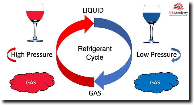
In the refrigeration cycle the refrigerant will only exist in two phases, as a LIQUID or a GAS. This is what it’s all about. The refrigerant just keeps going in a circle from Gas to Liquid, then back to Gas again. This is the basic refrigerant cycle, the continuous changing of the state of the refrigerant from gas to liquid, liquid to gas, over and over again while in the process of moving heat around. The high pressure side is related to heat, while the low pressure side is related to cooling.
So this is how we will find the refrigerant inside a Refrigerator, Air Conditioner or Chiller. Its either on the low or high side and in either liquid or vapor form. There are only four possibilities. LOW, HIGH, LIQUID or VAPOR.
Components of Refrigeration Cycle
Before we explain the refrigeration cycle, we need to understand the four basic components which are:
Compressor
Condenser
Metering Device
Evaporator
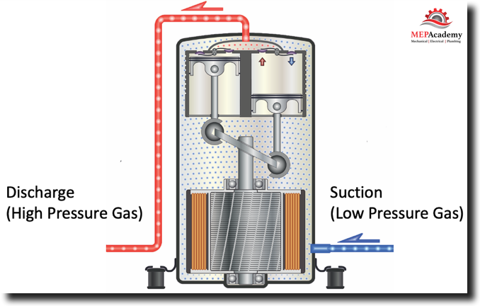
Compressor (From Low Pressure Gas to High Pressure Gas)
The compressor is what does most of the hard work in a refrigerant cycle. It pumps the refrigerant around the system. It does this by creating a pressure difference between one side of the compressor and the other side. The compressor is what creates the low and high sides of the system.
There are different types of compressors which will cover in another video, but the purpose is to move the refrigerant around the system. The compressor will only work with GAS, no liquid, so its important that only vapor enters the compressor inlet or suction line.
Refrigerant Compressor
The compressor takes low pressure refrigerant and increases it to high pressure refrigerant. And as we learned when the pressure goes up so does the temperature of the refrigerant.
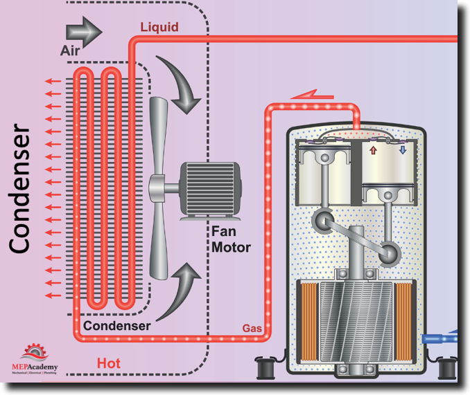
Condenser (From High Pressure Gas to High Pressure Liquid)
The condenser does just as the name implies, it condenses the refrigerant from a High Pressure Vapor back into a High Pressure liquid by removing the heat either to the air stream or through a water-cooled heat exchanger. Remember heat wants to balance its self out, so that everything is the same temperature, it does this by transfer heat to a cooler medium. From the hot refrigerant to the cooler air blowing over the condenser coil.
Condenser Section of Refrigeration Cycle
The air blowing over the condenser comes in contact with the hot surface of the copper coil (pipe) as represented in the image. This causes the refrigerant vapor in the condenser coil to condense back into a liquid.
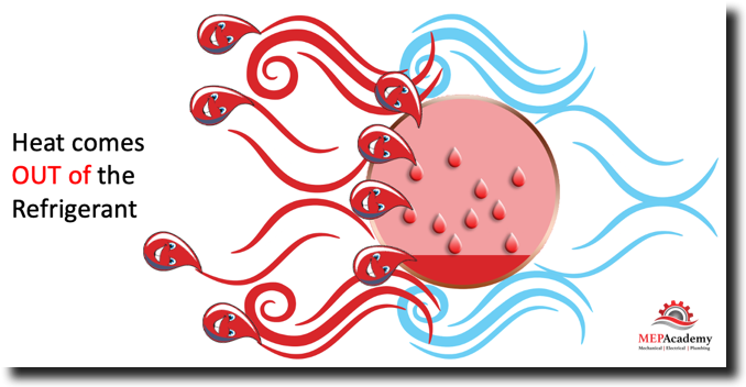
Condenser Heat Rejection
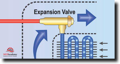
Metering Device (Expansion Valve) (From High Pressure Liquid to Low Pressure Liquid)
The metering device only allows as much liquid refrigerant that is required to pass through from the high side to the low side. The metering device is like the Parking Cop at the Professional Ball Park, only allowing as many cars to pass as there are parking stalls available in that area. The metering device only allows refrigerant to get through according to the cooling requirements.
Refrigerant Expansion Valve – Metering Device
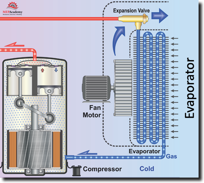
Evaporator (From Low Pressure Liquid to Low Pressure Gas)
The evaporator does as its name implies, and it evaporates the liquid into a gas.
Evaporator – Refrigerant Evaporates absorbing Heat in the Process
As warm air passes over the Evaporator coil the heat is absorbed by the liquid refrigerant causing the refrigerant to boil off into a gas. The air leaving the coil will be much cooler as it has given up some of its heat to the refrigerant. See diagram below.
Evaporator Process
As the liquid refrigerant passes through the evaporator the warm air passing over the evaporator gives up its heat to the liquid refrigerant passing through the coil tubing of the evaporator causing the refrigerant to evaporate (convert from liquid to gas). The air gives up some of its heat, thereby becoming cooler. Remember as long as there is a temperature difference between two items, the warmer one will transfer some of its heat to the cooler one.