


Maintaining a set of estimating standards will create a more efficient estimating department or disciplined estimator. By creating estimating standards you will be able to quickly identify systems from one drawing to the next, and be able to assemble your estimates in the same manner from one project to the next. Estimating standards make reviewing and bidding projects more efficient by having a structured protocol for each step of the way.
System Identification (Color Coding Chart)
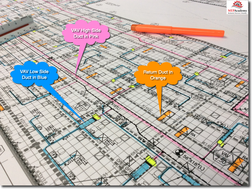
When starting a takeoff you must have a way to record what has been taken off and what has yet to be done. This is best done by coloring the portion of the ductwork that has been takeoff. If you’re using an estimating software program, then the coloring or indication of what has been taken off will be automatically done for you. All you have to do is setup the colors per system type, such as VAV High Side, VAV Low Side, Supply, Return and Exhaust air systems.
It’s also important to color each system a different color, as this will help you quickly identify a system by its equivalent color code. For example; Low Pressure Supply Air would always be colored light blue, while return air would be colored orange. By following this simple rule of coloring from one drawing to the next, it will make it easy to view drawings using a visual representation of system types.
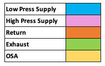
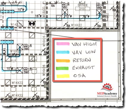
These are the standard colors we will be using through-out this training. It is also helpful for those that may not be familiar with your color coding, to put a legend on the drawing as shown in the picture below.
It’s important to color your takeoff as you record the material taken-off, this will ensure that you can quickly recognize where you last left off. It’s also important that you don’t color in any of the material that you haven’t taken off into your takeoff sheet or computer.
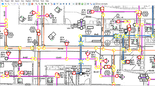
Computer estimating programs also use different colors to represent different portions and system types in a material take-off. Shown above is the Trimble AutoBid Sheet Metal Onscreen Takeoff View with different colors shown for the different system types.
Your company should establish a standard that everyone uses in order to maintain consistency. After a while you can instantly recognize a system based on the colors that were used during takeoff as we’ll show you below.
High Pressure Supply Ducts
Begin your takeoff at the source of the air, which is often a main duct coming out of a shaft as shown below for this VAV high-side supply duct in a commercial HVAC system. It’s not actually seeing high static pressure, but the nomenclature is used to distinguish the low side from the high-side of the VAV terminal box. The specifications will define the static pressure to be used at various location in the duct system.
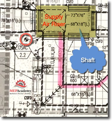
The first item at the shaft wall is a tap then a CSFD (Combination Smoke & Fire Damper). Remember that shafts can carry air from one floor to another and will usually require some form of smoke and or fire damper to protect the migration of smoke from one floor to another through the ductwork.
The duct will act as a transportation highway bringing toxic smoke that may occur from a fire on another floor through the shaft, so it is important to be aware of the requirements for smoke and fire dampers. We also know that a Smoke or Fire Damper will need an access door in the duct and another in the ceiling if the ceiling is constructed of inaccessible material like gypsum board.
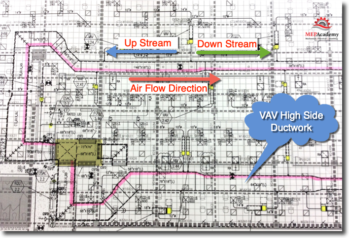
In this example we will take off all of the High-side VAV Supply main duct and color it pink to indicate the high pressure side. Of course, most likely it’s not high pressure ductwork, but can be anything from +2” sp to + 6” sp. We use this terminology only to distinguish the upstream from the downstream side of the VAV box.
As you can see in the drawing it’s easy to now identify where the high-side supply air duct main runs through-out the building.
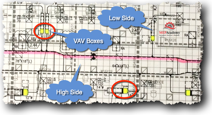
When we have finished with the High-side main duct we will color all of the VAV Terminal Units or VAV Boxes with a yellow highlighter. You could also do this in the beginning, while counting how many VAV boxes there are.
This will help us quickly visualize the demarcation between high-side and low-side. The VAV box separates the two pressure classes as often defined by Engineers and the static pressure requirements as seen by the duct.
Low Pressure Supply Duct
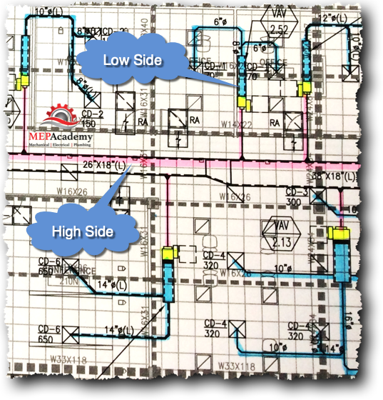
After completing the high pressure side takeoff then you can start with the low pressure side of the VAV box. We will use blue as our color for the low pressure side. This will allow you to quickly see where the high and low side start and stop.
Return Air Ducts
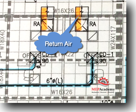
After completing the high and low pressure duct takeoff then proceed to the return air system. In this example the return air is not ducted back to the air handler, it is returned through the attic space un-ducted.
What the engineer has shown is sound boots in each office or space so that noise is not transmitted from one office to another through the return air grilles. In this case it appears that each office space has full height walls that would trap any return air, so a means for getting out of the space is required.
Additional Fittings
Another thing to consider is that engineers are not detailing the design drawings and additional fittings will be needed as the drawings are considered diagrammatic. This means that you will need to make some judgment as to where additional fittings will be required as shown in the below picture.
Outlined in the red box in the picture below you can see that the VAV box is at a similar elevation as the main duct. The VAV box is shown in yellow and the main duct has been colored pink. The low pressure duct in blue starts from the plenum of the VAV box and turns and goes back over the main duct without any fittings shown.
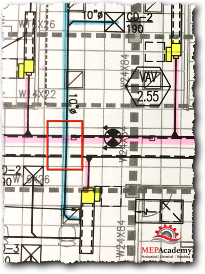
It would be impossible to do this if the VAV box and main duct are at the same elevation because that would mean that the low pressure duct is also at the same elevation.
In this case its best to add at least four (4) additional fittings, either 90 degree or 45 degree elbows. This will get you up and over the main duct and then back down over the other side of the main and back down to the starting elevation. If you are changing elevation of the low pressure duct then you can use just two (2) fittings to get you up over the main duct and then remain at that elevation without dipping down back to the starting elevation.
Overall View
It should now be easy to spot anything that was missed. You will notice any white areas of the drawing that haven’t been colored that may contain a piece of duct.
Sheet Metal Material Takeoff Sheets
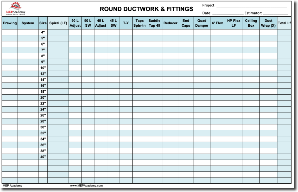
Round Duct Takeoff Sheet
When doing manual takeoffs without the benefit of a computer program, you should use preprinted forms or a computer spreadsheet to tally your material takeoff.
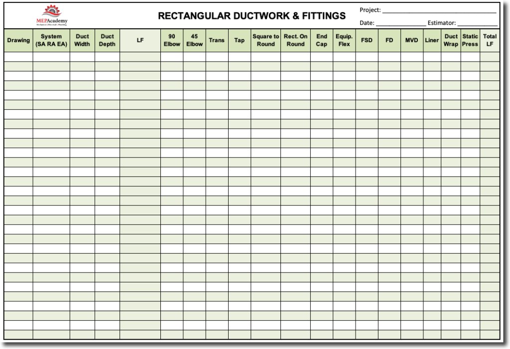
Rectangular Sheet Metal Takeoff Sheet
The most common fittings are shown on the takeoff sheet. You can rename any of the fittings that you commonly use in your area. The idea is to make takeoff’s as easy as possible without duplicating efforts.
Sheet Metal Breakdown
A sheet metal takeoff needs to be properly broken down so as to allow for easy labor analysis when you are complete. To do this, you will need to separate ductwork according size ranges that use similar productivity factors, such as is shown in this replication of the Military’s productivity schedule.
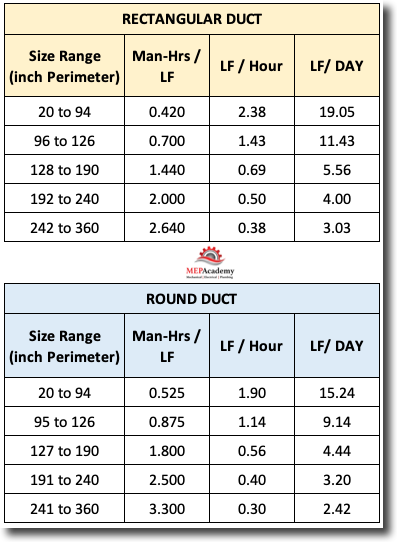
As can be seen in the chart above, the sizes are broken down into ranges based on the full perimeter of the ductwork. The perimeter is the same as the stretch-out we discussed in a previous section. If you have a 24” x 12” section of ductwork, then the perimeter (stretch-out) would be as follows;
24” + 12” + 24” + 12” = 72”
This would fall on the first line of the chart for rectangular ductwork.
The chart separates rectangular duct into different size ranges. All rectangular ductwork that ranges in size from 20” to 94” in total perimeter, equals 2.38 Linear Feet per Hour or 19.05 Linear Feet per Day. This would equal any ductwork where the perimeter or stretch-out length fell within those values, such as; 22” x 24” ductwork, which when stretched out equals a 92” perimeter (22” + 24” + 22” + 24” = 92”)
Zone, System & Size Breakdown
When doing a sheet metal takeoff, it’s helpful to separate the takeoff according to the following;
- Drawing # (M-1, M-2)
- Zone (AHU-1, or AC-5) Air Handling Unit #1 or Air Conditioner #5
- System (Supply, Return, Exhaust, Relief, etc.)
- Material Type
- Size Ranges
By breaking out your takeoff in a structured way like this, it makes it easy for labor analysis and addendum modifications. Your takeoff might be organized as follows;
M-1, AC-5, Supply Air.
M-1, AC-5, Return Air
M-1, AC-5. Outside Air
If a week later an addendum was issued that changed the ductwork on AC-5, this would be an easy change for you since you have isolated it within your takeoff.
Starting the Takeoff
It’s best to start at the source of the air being provided into the duct. This could include an Air Handler, Air Conditioner, Fan or just the most upstream section of the ductwork, where it is at its largest dimension and CFM capacity.
Estimating Review Meeting
Depending on the size of your company there will be varying amounts of individuals participating in the estimate review. For a small company this could fall squarely on the owner or the estimator. For larger companies, the estimate review meeting could include field supervisors, estimating managers, salespeople and other decisions makers. The larger the project, the larger the potential estimate reviewers involved.
For this estimating review meeting, be sure to have copies of the labor reports for all those who will be attending, along with a copy of the sheet metal specialties sheet. Be organized and professional at all times, this is where you establish your credibility as an estimator, by the way in which you present yourself and your estimate.
Estimating Sign-Off Threshold Amounts
Some companies will establish threshold for sign-offs of the estimate based on the dollar amount of the bid. For project greater than a million dollars, maybe your estimating standards would require that the bid be reviewed and signed by an executive of the company. The more difficult the project, the more you want to get an experienced opinion of others.
Example of Threshold Sign-off Authority
- Estimator $0 to $250,000
- Estimating Manager $0 to $500,000
- Vice President $0 to $2,000,000
- Owner. President $0 to Infinity
Project Kickoff Meetings
When a project is successfully won and the project documents have been handed over to the construction department, there should be some form of project kickoff meeting. During this meeting the estimating team or individual estimator would explain the approach to the estimate and the values of the estimate.
At this point in the process, the estimator is usually the one most intimate with the project scope and details, so is one of the best to communicate all the information about the project. The project kickoff meeting will ensure that key information is transferred to the team that will be responsible for building the project.
Project Closeout Meetings
It’s also good to have some form of project closeout meeting, or lessons learned feedback so that anything of significance learned while executing the construction of the project can be shared with the estimators or estimating department to make them more efficient in future estimates.
Acknowledging where the estimate went over or under the estimated amount will help to make future adjustment in labor or material values as required to bring each category of the estimate in alignment with the actual cost. Realizing that labor is always going to be the biggest variable, this is an area for continuous study to better understand how your company performs in various environments and conditions.
Quality Control
Double checking your calculations and having a second set of eyes review the bid and proposal will help eliminate possible errors. Your company should have some measure of ensuring the accuracy of your bids. This can be by using estimating software, bid review meetings or several people reviewing the bid and proposal for projects exceeding a certain dollar value.
Summary
Establish estimating standards for your company so that as you grow there will be a way to have all your estimates uniformly arranged. This will make it easier and quicker to review and audit estimates.
Estimating standards will provide consistency from one estimate to the next. This includes using one estimating spreadsheet that gets updated as things change, but which mostly remains consistent from one estimate to another.
Introduction to Sheet Metal Estimating (Free Course)
- Chapter #1 – Introduction to Sheet Metal Estimating
- Chapter #2 – How to Read the Specifications
- Chapter #3 – Understanding the Front End Documentation
- Chapter #4 – Sheet Metal Estimating Standards
- Chapter #5 – Labor and Material Databases
- Chapter #6 – MEP Estimating Software
