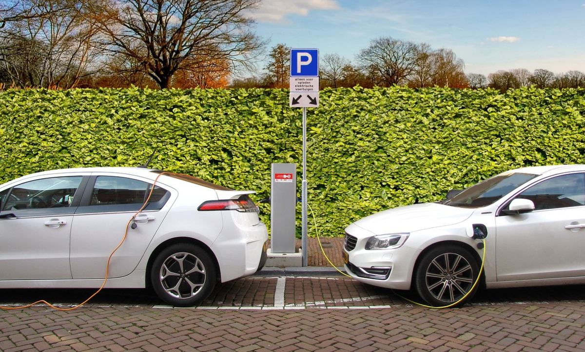
Electric Vehicle Charging Station. Electric vehicle (EV) charging stations provide electrical energy to recharge the batteries of electric vehicles. There are different types of charging stations, each with different charging speeds and power levels.
If you prefer to watch the video of this presentation than scroll to the bottom or click on this link. Electric Vehicle Charging Station
Here is a brief overview of how some of the common types of charging stations work:
Level 1 Charging
Level 1 charging is the slowest and least powerful type of charging, as it uses a standard 120-volt household outlet to deliver electricity to the vehicle. This type of charging can take up to 24 hours to fully charge an electric vehicle, depending on the battery size, this is equivalent to a charging rate of around 2 to 5 miles of range per hour of charging.
Checkout these EV Chargers hereLevel 2 Charging
Level 2 charging is faster than Level 1, as it uses a 240-volt circuit to deliver electricity to the vehicle. Level 2 charging stations can fully charge an electric vehicle in 4-8 hours, depending on the battery size and the charging station’s power output, this is equivalent to a charging rate of around 10 to 60 miles of range per hour of charging.
Level 3 – DC Fast Charging
DC fast charging, also known as Level 3 charging, is the fastest and most powerful type of charging. DC fast chargers can charge an electric vehicle to 80% capacity in as little as 20-30 minutes. These charging stations use direct current (DC) to deliver electricity directly to the vehicle’s battery, bypassing the onboard charger.
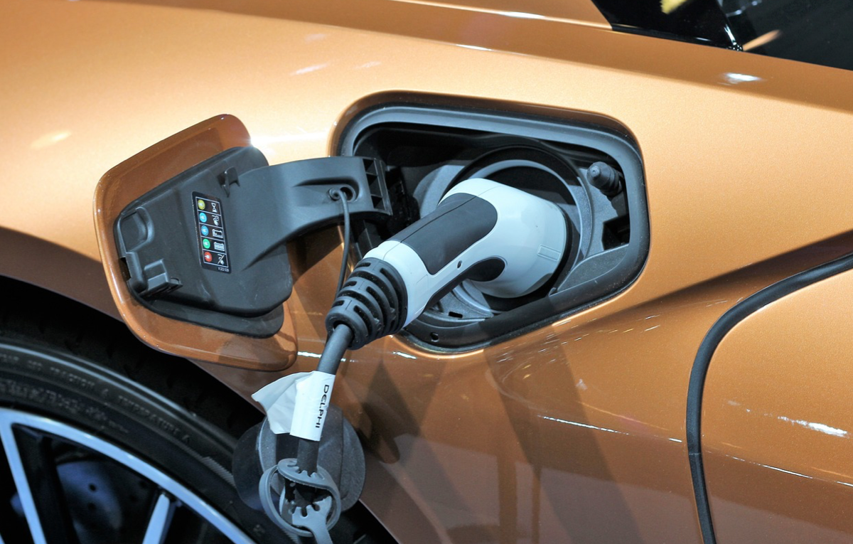
To use an electric charging station, drivers need to plug their vehicle’s charging port into the charging station’s charging cable. When an electric vehicle is plugged into a charging station, the charging station communicates with the vehicle’s onboard computer to determine the maximum charging rate that the vehicle can handle. The charging station then supplies the required amount of electrical energy to the vehicle’s battery, which is stored in the battery’s cells.
Checkout these EV Chargers here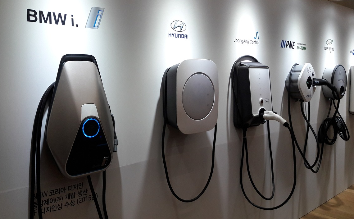
Most charging stations are equipped with safety features that ensure that the charging process is safe and efficient. For example, the charging station will automatically stop charging if the battery is full or if there is a problem with the charging equipment or the vehicle. Additionally, many charging stations are equipped with monitoring systems that track the amount of energy used and the time spent charging.
Overall, electric charging stations are essential to the widespread adoption of electric vehicles, and they work by providing the necessary electrical energy to recharge the vehicle’s battery in a safe and efficient manner. They can be located just about anywhere.
Where are EV Charging Stations Located?
Electric vehicle (EV) charging stations can be found in various locations, including:
Homes: EV owners can install Level 1 or Level 2 charging stations in their homes, typically in their garage or driveway.
Public places: EV charging stations are becoming increasingly common in public areas such as shopping malls, parking garages, airports, hotels, gas stations, and public parks. Some cities also have dedicated public charging stations installed on streets and in public parking lots. Public charging stations are usually operated by a charging network provider or the property owner, and they may require payment for use.
Workplaces: Many companies are installing EV charging stations in their parking lots to encourage employees to use electric vehicles, and are usually free to use for employees.
Highways and rest areas: Governments and private companies are investing in building networks of fast charging stations along highways and in rest areas to allow EV drivers to travel longer distances.
Residential buildings: Many apartment complexes and condominiums are now offering EV charging stations as an amenity to their residents.
Overall, the availability of charging stations varies depending on the location and region. However, with the increasing popularity of electric vehicles, more charging stations are being installed in various locations to support the growing number of EV drivers. Public charging stations can be located on mobile applications.
Checkout these EV Chargers hereMobile Applications for Locating EV Stations
There are several mobile applications that can be used to locate electric vehicle charging stations. Some of the most popular apps include:
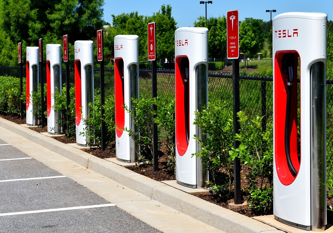
Tesla – If you own a Tesla vehicle, the Tesla mobile app provides a map of Supercharger and Destination Charging stations, as well as real-time updates on charging progress and estimated charging times.
PlugShare – This app allows you to search for charging stations by location and filter by charging network, charger type, and more. It also includes information about the availability of charging stations, ratings and reviews from other users, and the cost of charging.
ChargePoint – This app provides real-time information about the availability of ChargePoint charging stations, including pricing, location, and charger type. You can also reserve a charging spot and receive notifications when your vehicle is fully charged.
EVgo – This app provides information about EVgo charging stations, including location, charger type, and pricing. It also includes features like remote start and reservation of charging spots.
Greenlots – This app allows you to find charging stations and view availability, pricing, and charger type. It also includes features like reservation of charging spots and the ability to track charging history.
Electrify America – Electrify America is a network of charging stations that provides a mobile app that allows users to locate charging stations and manage their charging sessions. The app provides real-time updates on the availability of charging stations, charging rates, and payment options.
These apps are just a few examples, and there are many other options available in app stores for both Android and iOS devices. Overall, these mobile applications can be very helpful for electric vehicle owners to locate charging stations, plan their trips, and manage their charging sessions.