How Heat Recovery Wheels Work. Heat recovery wheels, also known as heat wheels or rotary heat exchangers, are a type of energy recovery device that are commonly used in HVAC (Heating, Ventilation, and Air Conditioning) systems to recover and reuse the heat energy that would otherwise be lost to the environment. Heat recovery wheels are designed to work by transferring heat between two air streams that are flowing in opposite directions, without mixing the two air streams together. We’ll show you how they’re used in a hospital and a locker room at your local gym.
If you prefer to watch the video of this presentation, then scroll to the bottom or click oaths link. How Heat Recovery Wheels Work.
Here’s how Heat Recovery Wheels work.
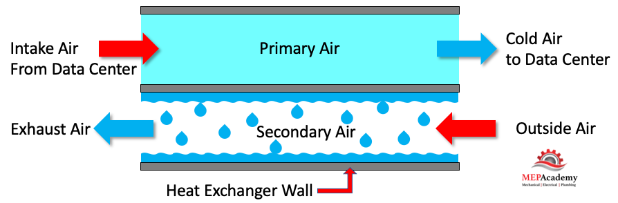
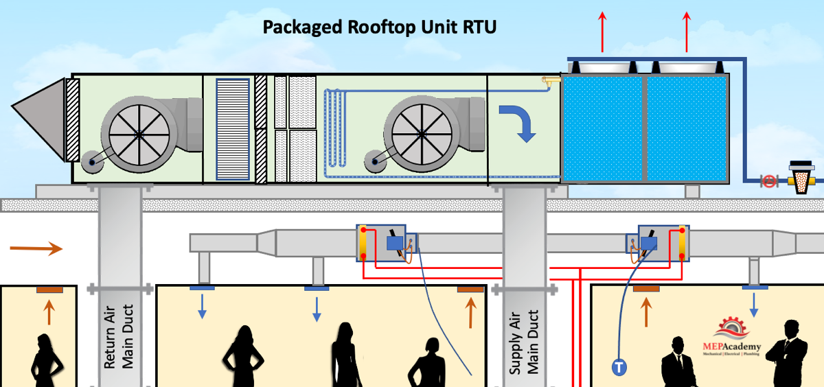
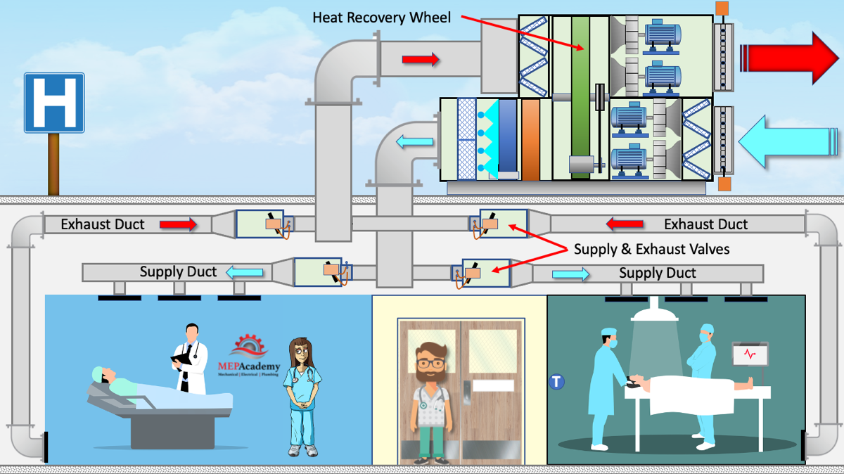
- Heat recovery wheels are typically installed in the supply and exhaust air ducts of an HVAC system. The supply air duct carries fresh air into the building, while the exhaust air duct carries stale air out of the building.
- As the two air streams flow past each other, the heat recovery wheel rotates to transfer heat energy from the warm, stale air to the cool, fresh air. This transfer of heat energy occurs using a heat-absorbing material that is typically made of aluminum or a similar metal for sensible wheels and a moisture absorbing material like silica gel or a zeolite molecular sieve for an Enthalpy recovery Wheel.
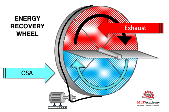
- The heat recovery wheel works by capturing the heat energy from the outgoing air stream as it passes through the heat-absorbing material. The wheel then rotates and transfers this heat energy to the incoming air stream as it passes through the same material in the opposite direction.
- As a result, the fresh air entering the building is pre-heated, while the exhaust air leaving the building is cooled. This helps to reduce the overall energy consumption of the HVAC system, as less energy is required to heat or cool the incoming air.
- Heat recovery wheels are most effective in climates where there is a large temperature difference between the indoor and outdoor air. In colder climates, the wheels can help to reduce heating costs by pre-heating the fresh air, while in warmer climates, they can help to reduce cooling costs by pre-cooling the fresh air.
- Energy recovery wheels can be a separate piece of equipment or come pre-installed in an air handler.
It is important to note that proper maintenance and cleaning of the heat recovery wheel is essential for optimal performance and energy savings. Dirty or clogged wheels can reduce the effectiveness of the system and lead to increased energy consumption.
Checkout these Heat Recovery Systems hereThere are several types of Heat Recovery Wheels. One type will capture sensible heat only and the other is an enthalpy wheel, often referred to as a desiccant wheel, which will capture sensible and latent heat.
Sensible Heat Wheel
With the use of a sensible heat recovery wheel the dry bulb temperature of the air will be increased or decreased depending on the outdoor temperature and setpoint. There will be no effect upon the moisture content or latent heat of the air, as no moisture is transferred between the two air streams.
Enthalpy Wheel
With the use of an enthalpy wheel or total energy wheel, the moisture content or latent heat of the air will be affected. Both sensible and latent heat will be transferred using an enthalpy wheel. The amount of moisture transferred is dependent on the amount of water vapor in the air. Moisture is transferred between the two airstreams using a desiccant which absorbs or adsorbs water vapor from the high-pressure vapor airstream and releases it into the lower pressure vapor airstream.
Capacity Control of Heat Recovery Wheels
When the load of the system varies the wheel can adjust its speed using a variable frequency drive (VFD), or a bypass duct can be installed around the wheel to reduce the volume of air that travels through the heat recovery wheel.
Heat Recovery Wheel Effectiveness
The effectiveness of the heat recovery wheel is determined by how much of the energy is transferred between the two airstreams. This is affected by the amount of air flow and the difference in energy between the two airstreams. The calculation looks like this.
Equation for Effectiveness. E = [Vs x (T1 – T2)] / [Vmin x (T1 – T3)]
E = Effectiveness
T1 = Outside Air Temperature (°F DB) or Enthalpy (btu/Lb.)
T2 = Supply Air Temperature (°F DB) or Enthalpy (btu/Lb.)
T3 = Return Air Temperature (°F DB) or Enthalpy (btu/Lb.)
Vs = Volume of Supply or Outside Air (CFM)
Vmin = Volume Minimum. Lowest CFM, either Supply or Outside Air (CFM)
Using the standard equation for heat transfer, we can modify it to include our effectiveness factor to determine the total heat transferred by the heat recovery wheel.
Sensible Heat Transfer Equation
Standard Equation. Qs = CFM x 1.08 x Delta-T (T1 – T3)
Modified Equation. Qs = E x CFM x 1.08 x Delta-T (T1 – T3)
Total Heat Transfer Equation
Standard Equation. QT = CFM x 4.5 x Delta-Enthalpy (h1 – h3)
Modified Equation. QT = E x CFM x 4.5 x Delta-Enthalpy (h1 – h3)
E = Effectiveness (Sensible or Total)
Qs = Sensible Heat Transferred (btu/hr.)
QT = Total Heat Transferred (btu/hr.)
h1 = Outside Air Enthalpy (btu/Lb.)
h3 = Return Air Enthalpy (btu/Lb.)
The Heating Season for Heat Recovery
When heating is required and the temperatures outside are very cold, the use of a heat or energy recovery wheel can save energy by removing heat from the exhausted airstream. No matter what the season an energy recovery wheel can retrieve needed heat or expel unwanted heat from the airstreams.
ASHRAE 62.1 Air Classifications
Air is classified according to ASHRAE 62.1. The classification indicates whether the air can be recirculated within the same space or transferred to another space based on the classification of that space.
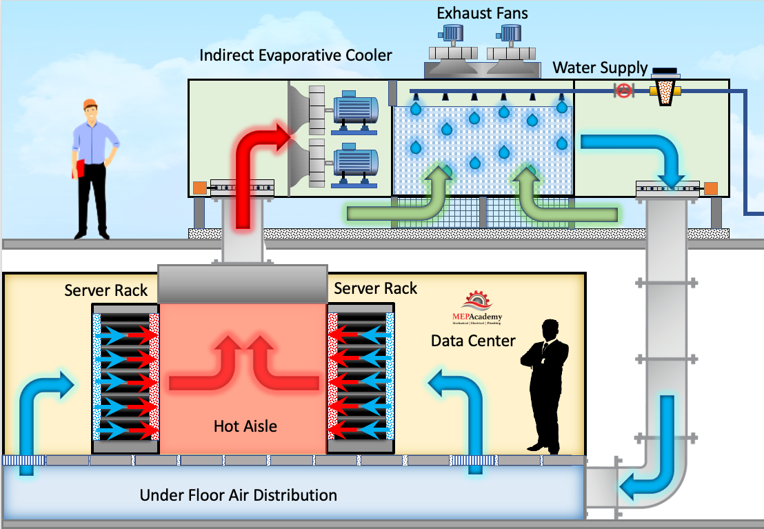
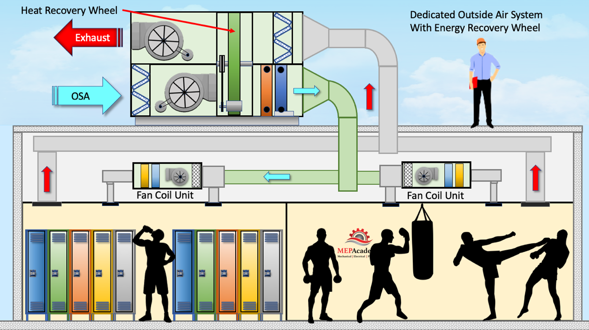
In the above image we show an air handler providing 100% outside air to a locker room and gym. The air handler has a heat recovery wheel to capture energy that would otherwise be wasted. The locker room in our example is considered Class 2 air and can be recirculated within the same space or other Class 2 spaces which includes the GYM portion of the building. Air is classified according to ASHRAE 62.1. The classification indicates whether the air can be recirculated within the same space or transferred to another space based on the classification of that space.
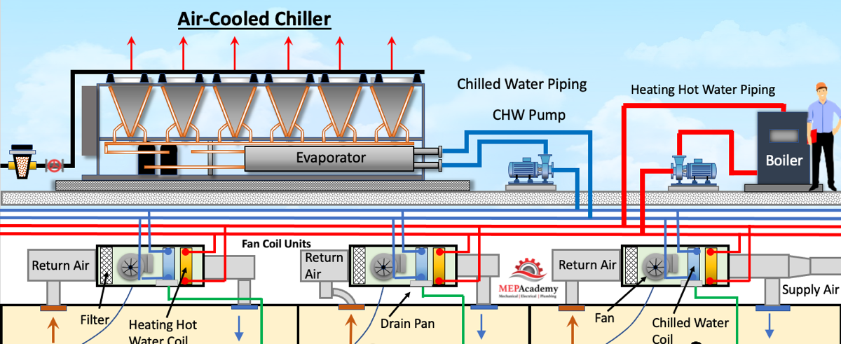
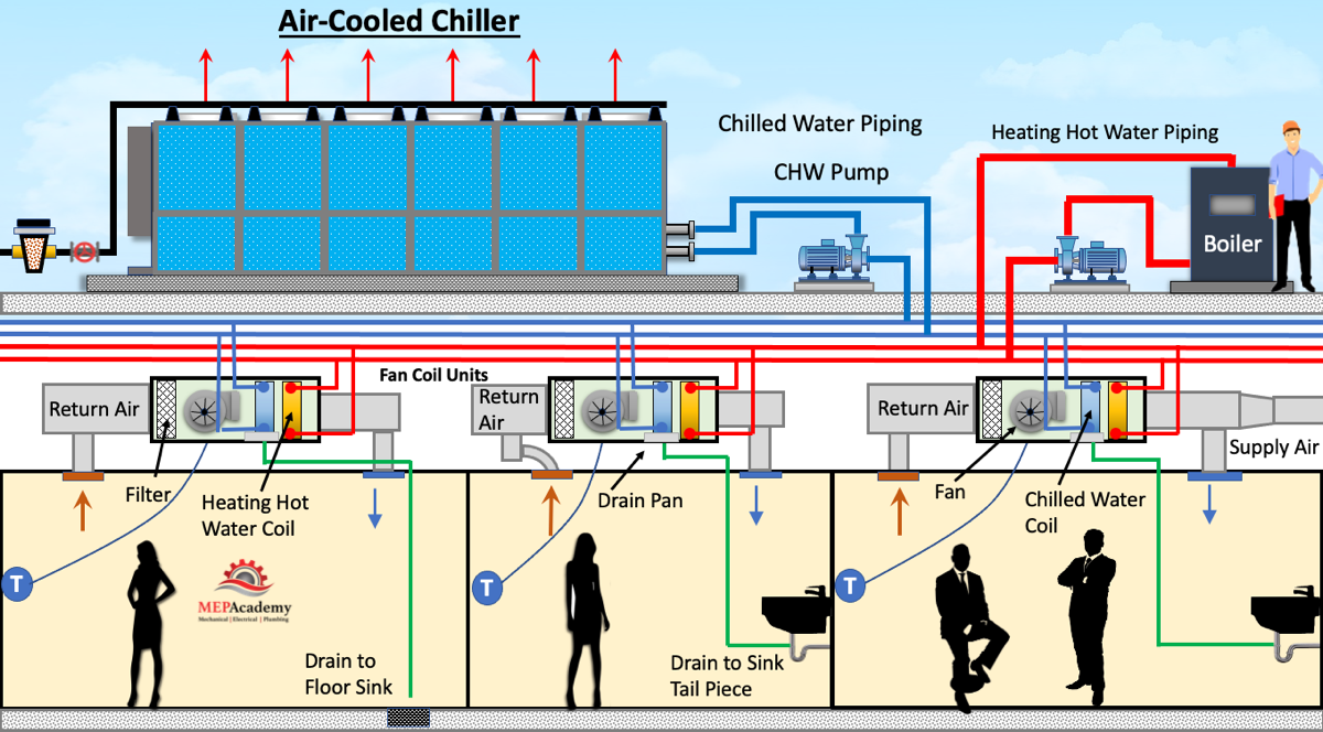
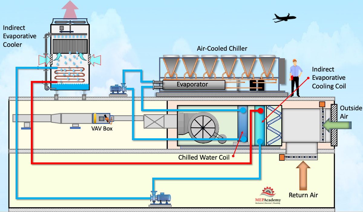
Another method is to remove the fan coils and just feed the space with the Air Handler which has a chilled water and heating hot water coil.
Checkout these Heat Recovery Systems here