3-Way Switch Wiring Explained. How Three-way light switches work. In this presentation we’ll learn how to control a light using a 3-way switch, which is convenient when there are two or more entrances to a room, or an upper and lower stairwell. We’ll show several different wiring configurations.
To watch the FREE YouTube version of this presentation, scroll to the bottom or click on the following link. 3-Way Switch Wiring Explained
Electrical Safety Warning
Whenever working with electrical be sure to shutoff the power at the electrical panel, and hire a qualified electrician to do the installation if you are not confident that you can do the job safely. Electricity can kill.
How do 3-Way Light Switches Work?
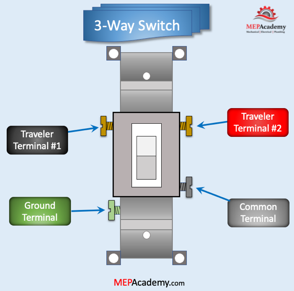
If we look at a 3-way switch, we’ll see that it has four terminal screws. We have two traveler terminals, which are usually identified by their light color of bronze or copper, a ground terminal in green, and a common terminal often a dark color. A 3-way switch won’t have an on/off designation that can be found on standard switches, as either position could be on or off.
Within the switch either one of the traveler terminals is connected to the common terminal, which can make or break the circuit depending on the position of the other switches traveler terminal matching or not. Its like the game of concentration where you turn over two playing cards trying to get them to match. When the two separate 2-way switches match on their traveler wires the light goes on, when they don’t match the light goes off. They can match with both on red or both on black, but not black/red or red/black.
The two traveler terminals can be on the same side of the switch or on opposite sides of the switch depending on the switch manufacturer.
Checkout these 3-Way Switches3-Way Switch Example #1
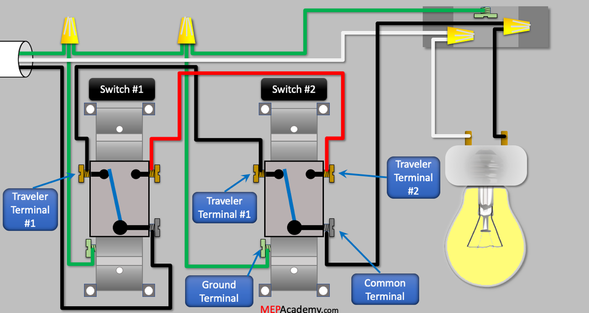
With this layout we have the light fixture between the two switches.
The incoming electrical power will connect to the common terminal of switch #2. Then we route the Black traveler wire for switch #2 to switch #1. We do the same thing for the Red traveler wire. From the common terminal on switch #1 we connect to the light. We bring in the neutral wire from the power source and connect directly to the light. We also bring in the ground wire from the electrical panel and connect to each of the switches.
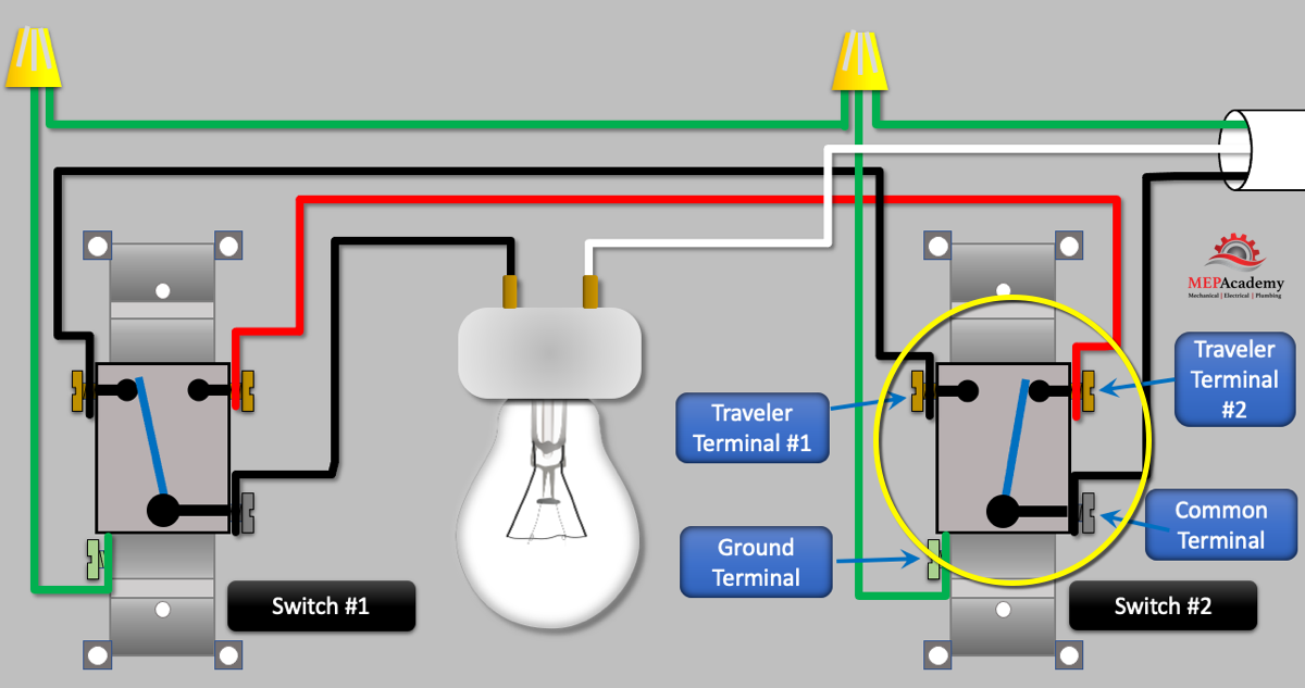
If we remove the switch covers and look inside we can see how these 3-way light switches work. Inside is a single pole double throw switch which provides each switch with an option to connect the common terminal with either the red or black traveler terminal.
When both switches are not in the same configuration, such as shown below we have one switches common connected to a black traveler and the other switch connected to a red traveler terminal. If we follow the power from the source, the black common wire from the electrical panel connects to the common terminal on switch #2, then passes through the switch to the black traveler terminal and then onto switch #1 where it dead ends.
If we flip switch #1 to the black traveler wire then the light comes on as the electrical circuit has a complete path through both switches to the light.
The process of turning on and off the light can occur from either switch, as we show here we now flip switch #2 to break the electrical circuit and shut the light off. In order to turn the light back on we have two options, we can flip switch #1 to the red traveler terminal so that it matches switch #2, or just flip back switch #2 to the black traveler terminal.
3-Way Switch Example #2
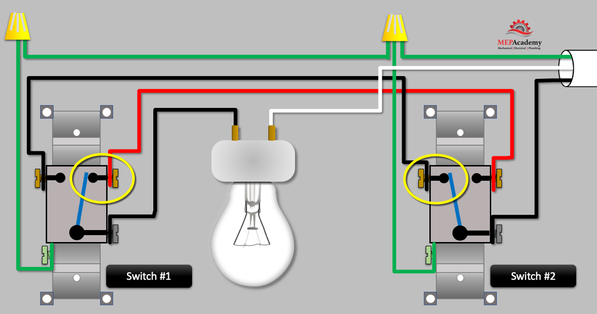
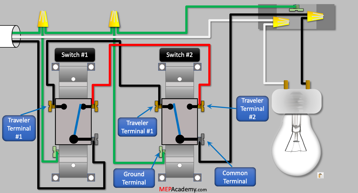
Depending on the layout of the space and where the wiring originates from, there are several versions of how the wiring can be done. We’ll show how to wire a 3-way switch with both switches wired before the light.
Will install a light fixture, and two switches. From the power source we’ll bring the black hot wire to switch #2 common terminal. Note, that this wire is usually black, but your wire could be another color.
Then we’ll run a black traveler wire from 3-way switch #2 to the same terminal on switch #1, this could be from left side of the switch to the left side of the other switch. Then we install an outlet box and run the black wire from the dark common terminal screw on the bottom of switch #2 to the light fixture. Now we have one complete path from the source all the way to the light.
Next, we install a red traveler wire from the right side of switch #1 to the right side of switch #2. This gives us a second optional path to the light through the red traveler wires from the black hot wire brought to the common terminal.
Checkout these 3-Way SwitchesNext, we install the incoming white neutral wire which is usually white, and we connect to the light fixture. Then we install the green ground wire from our source to the outlet boxes ground terminal, and then to each of the ground terminals on the switches. The ground is usually an insulated green wire or can be bare copper wire. In the fixtures electrical box there should be a place to land the ground wire.
We have 4 wire connections on each switch. Two travelers, one common, and one ground.
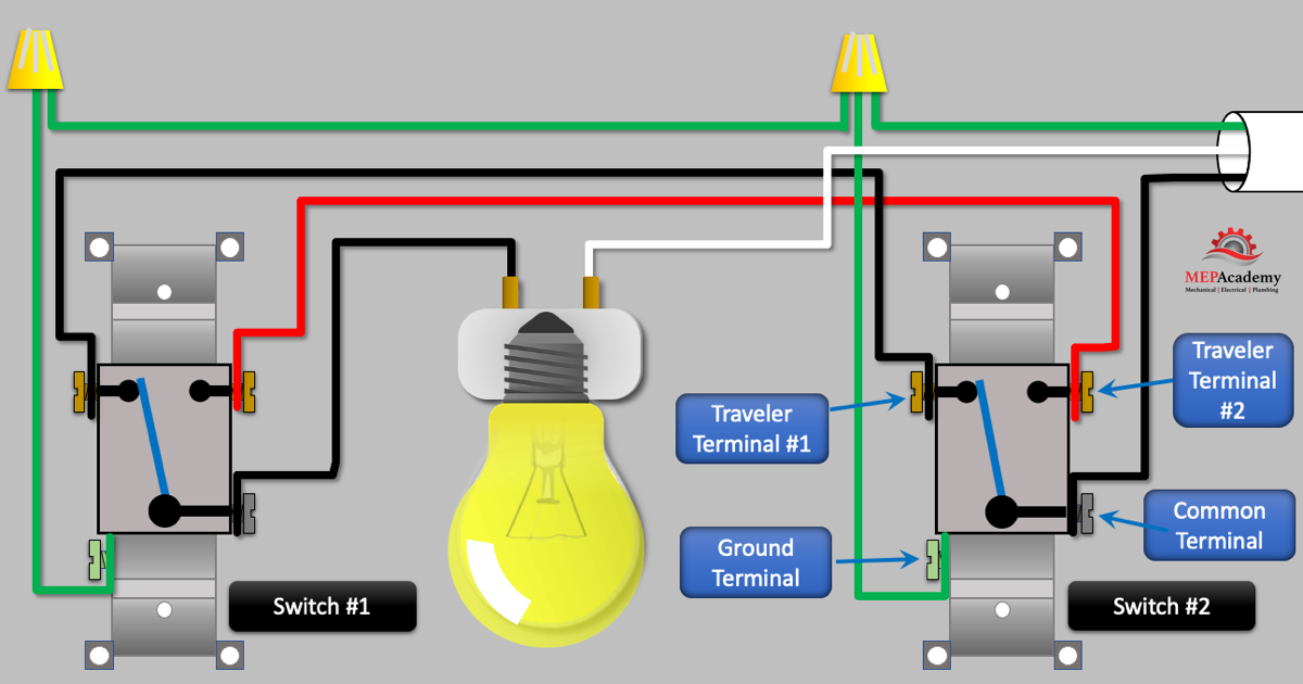
When we turn on the power and both switches have the same traveler terminal connected to common then the light will come on as shown above where both black traveler wires are in the same position. This could be either both black or both red travelers in the same position.
When one of the switches is flipped so as there is no matching traveler wire that provides a complete path to the hot common wire the light goes off as shown here with switch #1 being flipped off. The 3-way switch doesn’t indicate the light is on when the switch is in the up position, and off when in the down position. The light being off or on is determined when there is a matching pair of traveler wires that provide a complete path for the power to the light.
Inside the 3-Way Switch
If we looked inside we could see that each switch has a single pole and a double throw, meaning that the switch has two options, to either have the common connected to traveler terminal #1 or 2.
When both of the switches are on the same traveler terminal as shown here, the power runs through to the light. If either of the switches changes position then the light will go off. The electrical power comes through the black common wire connected to switch #2, and uses the red wire to reach terminal #2 on switch #1, where it flows through the common wire to the light, making a complete circuit.
Stairwell Example
First we mount a light above or stairwell and install a switch at the top and bottom of the stairwell. We bring in power using a black wire and connect to the common terminal on switch #1.
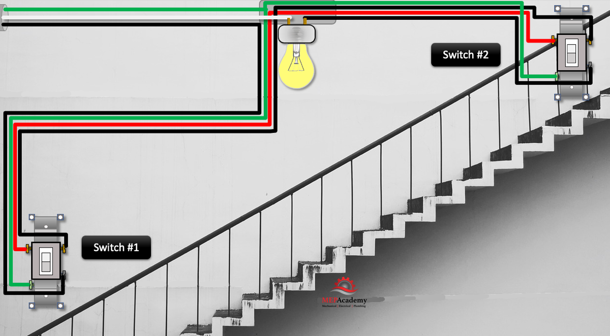
From switch #1 we run a black traveler wire to switch #2’s traveler wire terminal, and from the common on switch #2 we run a black wire to the light fixture. Then we run a red, second traveler wire from switch #1 to switch #2. We install a neutral wire from the electrical panel to the light fixture. Lastly we provide a green insulated ground wire from the panel to each of the light switches.