Taking the known values of 2,700 CFM and the new duct area of 36” x 12” we can find the new velocity. First the duct area needs to be converted to square feet.
In this presentation we’ll learn how to calculate the Total CFM in a section of ductwork or moving across a coil or other piece of equipment. Then we’ll learn what happens to velocity when we try to reduce our ductwork without reducing or CFM.
If you prefer to watch the YouTube Video of this presentation, scroll to the bottom or click the following link. Calculating CFM Video
Here is the formula that is used to calculate CFM or Velocity.
CFM, which is “Cubic Feet per Minute” = Velocity which is shown in “Feet per Minute” multiplied by the Area which is shown in “Square Feet.”
A cubic feet of air is a slice of air one foot by one foot, by one foot deep, which might look like this cube.
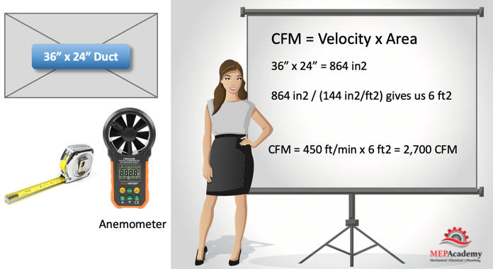
For example, to determine how many CFM were flowing through a duct section we can do the following. First we would measure the width and height of the duct. Let’s say it was 36” x 24”. Next, we could use some form of anemometer to get an average velocity reading across the duct section. Let’s say the velocity reading is 450 feet per minute. Now we can solve for the quantity of CFM flowing through this section of ductwork using the following formula.
CFM = 450 ft/min x the area, which is 36” x 24”
We’ll need to convert our duct dimensions in inches, into square feet, because we are looking to arrive at cubic feet per minute.
36” x 24” = 864 in2
864 in2 / (144 in2/ft2) gives us 6 ft2
CFM = Velocity x Area
Now we can enter the total square feet into our formula.
CFM = 450 ft/min x 6 ft2 = 2,700 CFM
Now we can use another version of this formula to calculate for velocity when the CFM and Area are known.
Solving for Velocity
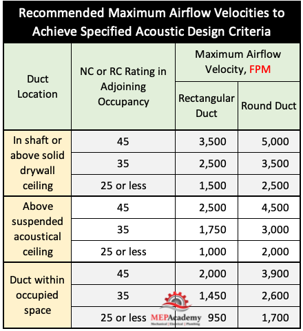
For recommended velocities in ductwork see ASHRAE’s handbook of Fundamentals. Depending on the noise criteria and where the duct is located the velocity for rectangular duct could be from 950 to 3,500 feet per minute.
ASHRAE Recommended Maximum Airflow Velocities
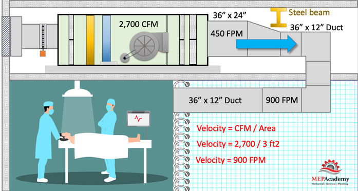
What happens to the velocity if you reduce the size of the ductwork with the same CFM. Let’s say that we reduce the ductwork to 36” x 12” in order to get under a beam. The approximate velocity can be calculated with the same formula, except this time will keep the CFM constant and not worry about static pressure or other factors that may affect the outcome slightly.
Velocity = CFM (ft3) / Area (ft2)
Taking the known values of 2,700 CFM and the new duct area of 36” x 12” we can find the new velocity. First the duct area needs to be converted to square feet.
36” x 12” = 432” in2
432 in2 / (144 in2/ft2) = 3 ft2
Velocity = CFM / Area
The new duct is half the area of the previous duct size, but it is carrying the same CFM. So, what happens to the velocity going through the reduced duct size in relationship to the previous velocity. Our velocity was at 450 feet per minute, now with the same CFM but a smaller duct we get 900 feet per minute.
Velocity = 2,700 CFM / 3 ft2 = 900 FPM
The ductwork area was cut in half from 6 ft2 to 3 ft2, but the velocity doubled from 450 FPM to 900 FPM. You can see there is a direct correlation between CFM and Velocity when the size of the duct or coil is changed.
Outdoor Air Intakes and air classifications Class 1 through Class 4 Air
Outside Air Intake Locations and Air Classifications. In this presentation we’ll learn where outside air intakes can be located and why. We’ll learn what the four classifications of air are, and how they relate to outdoor air intakes, including their Minimum separation distances as shown in ASHRAE 62.1 Table 5-1.
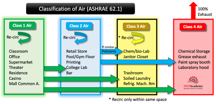
ASHRAE ranks air according to the level of contaminants in the air and the level of sensory irritation. The classification extends from Class 1 which is considered low contaminant level, to class 4 which is highly objectionable. Class 1 is the cleanest air classification, while class 4 is the worst.
Classification of air ASHRAE 62.1
Class 1 Air with low contaminant concentrations, low sensory-irritation intensity, an inoffensive odor is suitable for recirculation or transfer to any space in classes 1 through 4.
Class 2 air can be recirculated within the same space of origin, or transferred to another Class 2 or 3 Space used for similar purposes or has similar pollutants. Class 2 air can be transferred to class 4 spaces. Class 2 air can’t be transferred to the cleaner class 1 air spaces. Air is almost always transferred from the cleaner space to the dirtier classification of air, unless some method of air cleaning is used.
Class 3 air can be recirculated only within the same space of origin, and can’t be recirculated or transferred to any other space. Class 4 air can’t be recirculated or transferred to any space.
According to ASHRAE 62.1 Table 5-1
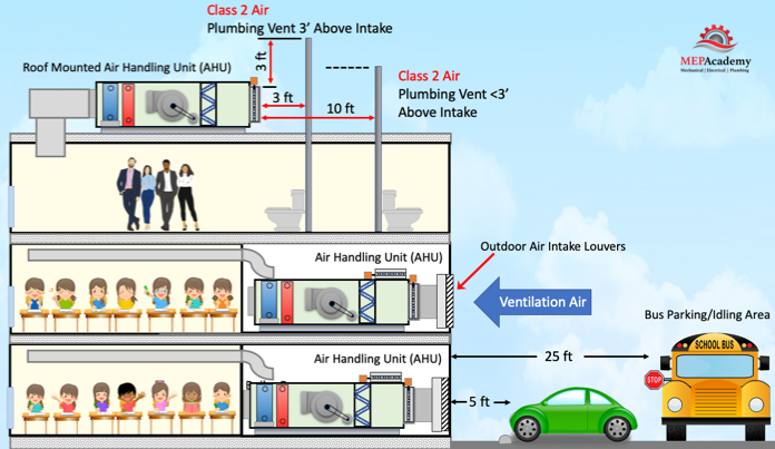
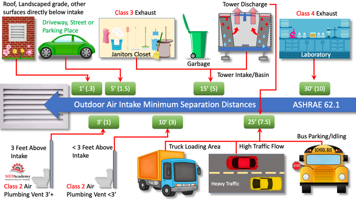
Per ASHRAE standard 62.1 the following minimum distances need to be maintained from the location of any Outdoor Air Intake. A minimum distance of 25 feet (7.5 meters) needs to be maintained between an Outdoor air intake and locations where Buses park or idle. A minimum of 5 feet (1.5 meters) is required between intakes and driveways, streets or parking places.
Class 2 Air Outdoor Intakes and Others
Any Class 2 exhaust or plumbing vent terminating less than 3 feet (1 meter) above the level of the outdoor intake is required to be located a minimum of 10 feet (3 meters) away. Class 2 Air has moderate contaminant concentrations, mild sensory-irritation intensity, or mildly offensive odors. (Class 2 air also includes air that is not necessarily harmful or objectionable but that is inappropriate for transfer or recirculation to spaces used for different purposes.)
A plumbing vent terminating at least 3 feet (1 meter) above the level of the outdoor intake is required to be located a minimum of 3 feet (1 meters) away.
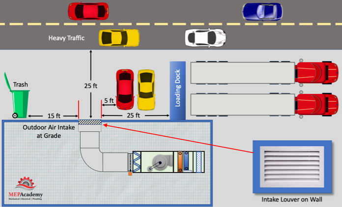
Continuing with ASHRAE Table 5-1, we have the requirement to keep Outdoor intakes a minimum of 25 feet (7.5 Meters) away from truck loading docks. A minimum of 25 feet (7.5 meters) must be kept between any highway with high traffic volume and an intake.
Outdoor Air Intake Louver and Distances to Loading Dock, Trash, Parking and Heavy Traffic
All around the world offices, schools, homes, and hospitals are built near highways and major roadways. Pollution from traffic has been documented to cause serious health problems, from physical to cognitive. The level of pollutants from traffic varies based on proximity to road and level of traffic. There are two sources of contaminants from traffic, the tail-pipe emissions and the physical wear and degradation of brakes and tires. You could also include noise as having adverse effects on health.
Any locations where trash is stored or picked up, including dumpsters will need to be at least 15 feet (5 meters) away from any outdoor intake.
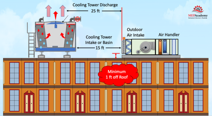
If you have a Outdoor Air intake near a cooling tower than the requirements are that the tower basin or intake to the tower needs to be a minimum of 15 feet (5 meters) away from the Outdoor Air Intake. The discharge of the cooling tower needs to be at least 25 feet (7.5 meters) away.
Cooling Towers and Outside Air Intakes
Potential contaminant sources are restricted on how close they can be to an air intake based on their classification. Air is classified based on the source of the contaminant, from class 1 to class 4.
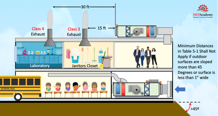
Here is a Class 3 exhaust shown the minimum distance of 15 feet (5 meters) away from this air handlers outdoor air intake. Class 3 is Air with significant contaminant concentration, significant sensory-irritation intensity, or offensive odor that is suitable for recirculation within the same space. Class 3 air is not suitable for recirculation or transfer to any other space.
Class 3 and Class 4 Air allowable distances to Outdoor Air Intakes
There is a laboratory exhaust system in this building which is classified as Class 4 air, which means its minimum distance to intakes is 30 feet (10 meters). Class 4 Air has highly objectionable fumes, gases, or potentially dangerous particles, bioaerosols, or gases at concentrations high enough to be considered harmful. Class 4 air is not suitable for recirculation or transfer within the space or to any other space.
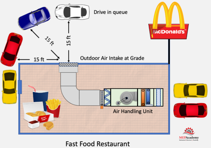
There is the requirement to maintain at least a 15 foot (5 meter) distance from a drive in queue to any outdoor air intake.
Outdoor Air Intake distance from Outdoor Air Intake Locations
When locating outside air takes its important to consider the possible sources of contaminants from the surroundings. ASHRAE 62.1-2019 4.3 requires an outdoor air quality investigation be conducted and documented. The survey should document any observation of odors, irritants, visible plumes, visible air contaminants, and include description of sources of vehicle exhaust on site and from adjoining properties.
ASHRAE Table 5-1 Air Intake Minimum Separation Distance
This table reflects the minimum distances that an exhaust or contaminant must be in reference to the outdoor air intake. There is an analytical method which can be used as an alternate procedure for determining separation distances between exhaust outlets and outdoor air intakes located in Appendix “B” of the standard.
Outdoor Air Intake Locations per ASHRAE 62.1 Minimum Separation Distances
Just because you maintain these distances doesn’t mean you will avoid entrainment, there is no magic to these distances. Other factors like wind direction and strength, building geometry and the exhaust design could have an adverse effect.
Roof, Landscaped Grade, or Another Surface Directly Below Intake.
If you live where snow is common, then the intake will need to be designed with the distances calculated from the average snow level. This snow average snow depth will be considered the ground level for distance calculations.
Summary
It’s important that air intakes be located safely away from sources of contaminants that could affect the occupant’s health. Outdoor air intakes provide fresh air for building occupants. The location and design of these intakes needs to include protection from contaminants, weather, such as rain, snow, puddling of water, wind-driven rain, and snow.
Energy Valve. In this article we’ll learn how an Energy valve works, how it saves energy, where it is used and how it can prevent the low Delta-T syndrome.
If you prefer to watch the YouTube Video of this presentation, then scroll to the bottom or click on this link. Energy Valve Video
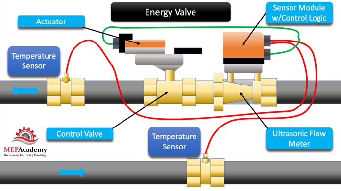
Here is the Energy valve. It has an ultrasonic Flow meter that measure the flow (GPM) going through the piping. This gives us the GPM in our equation. Then we have temperature sensors on the supply and return piping to our heat exchanger or coil. This will give us the Delta-T in our equation.
Energy Valve with Ultrasonic Flow Meter and Temperature Sensors
With these two values the Energy Valves onboard controls logic can determine the energy, or the Q in our equation which is the BTU/Hour. This consumption of energy can be used to bill a tenant for their use of the chilled water or heating hot water system.
To adjust the flow or GPM, the Energy Valve will modulate the Actuator on the Control Valve. The GPM is adjusted to reach the Delta-T setpoint of the Energy Value.
We can install these Energy Valves on the Coils feeding an Air Handling unit, and install Temperature sensors and the connecting cabling.
Air Handling Unit with Energy Valve
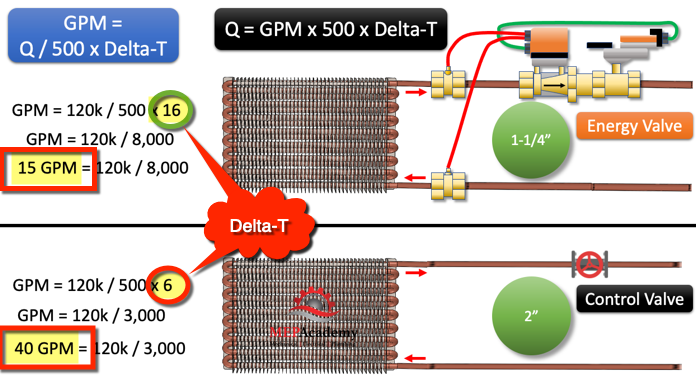
We can look at the difference between maintaining Delta-T with an Energy Valve and the traditional system. We converted our formula to solve for GPM. Using a heat load of 120,000 Btu/Hr. or 10-Tons, we get 15 GPM if the Energy Valve is maintaining the Delta-T at a setpoint of 16 degrees. The traditional system has slipped to a 6 degree Delta-T, requiring 40 GPM to get the required heat transfer. This additional GPM causes an increase in pump energy, and would require larger piping. The size of the piping for the Energy valve system would be 1-1/4”, while the traditional system would require 2” to match the same heat transfer quantity.
Comparison Between High and Low Delta-T Temperatures
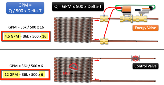
If the heat load drops to 36,000 Btu/Hr., which is 30% of the peak design load, then we get 4.5 GPM through the Energy Valve at a 16 degree Delta-T. The traditional system is requiring 12 GPM to get the required heat transfer. Saving energy requires managing the Delta-T through the heat exchanger so that the pumps and central plant equipment runs efficiently.
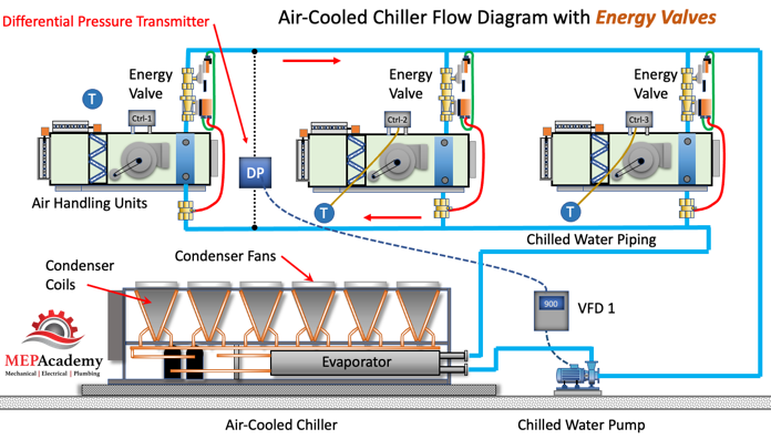
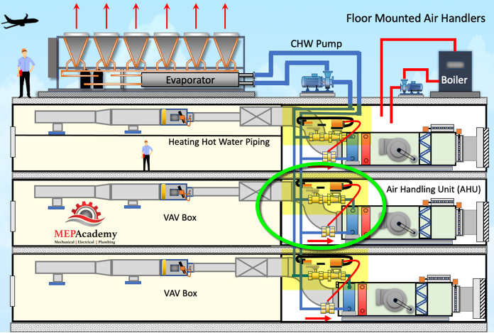
The Energy valve can be used with Air Handlers as shown here. The contractor installs the Energy Valve and a Temperature Sensor on the Chilled Water Supply piping. Connection can be made to a Building Management System for remote monitoring, data collection and programming.
Energy Valves installed on Chilled Water Coils of an Air Handling Unit
Fan Coils and Energy Valves
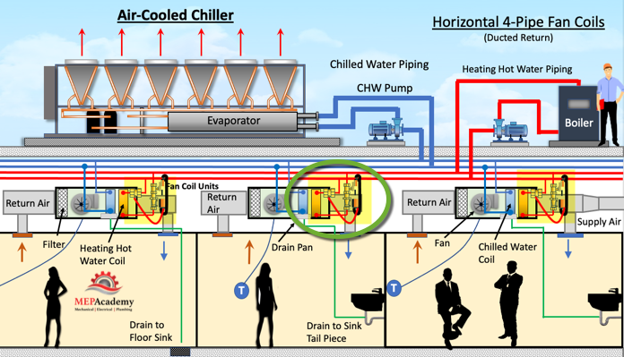
The Energy Valve can be installed on Fan Coil Units also.
Energy Valves installed on Heating Hot Water Coils of Fan Coil Units
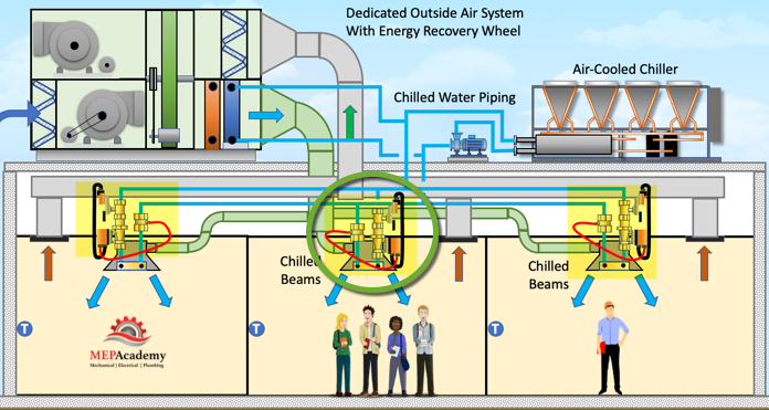
Chilled Beams and Energy Valves
The Energy Valve can be installed on Chilled Beams. The Valve can be installed on just about any coil or heat exchanger to manage Delta-T and avoid the Low Delta-T Syndrome.
Chilled Beams with Energy Valve
Low Delta-T Syndrome
Tracking the Delta-T of the water being delivered to HVAC Coils is important in maintaining an efficient system. The valve tracks the current Delta-T and compares it to the set-point Delta-T to be maintained, making adjustments as required to keep it at minimum set-point or above. To increase the delta-T, the valve will throttle to lower the flow of water through the coil. This gives the water more time to transfer heat.
There is a large cost in electricity consumed to run chillers to make chilled water. This makes it important to use the energy consumption power of this water to its maximum ability, which will occur with a higher Delta-T. Higher Delta-T systems also use less pump energy, as more energy is removed in a smaller volume of water. A delta-T of 16 is much better than a delta-T of 5 or less. The energy valve manages Delta-T to maximize the energy use of the system. To avoid low flow situations, there is a minimum flow setting of 30% when using the Delta-T manager
If you have a low Delta-T then the water is passing through the coil to quickly, not allowing enough time for heat transfer to occur. By managing the delta-T, the energy valve can reduce the flow (GPM) through the coil allowing enough time for the water to consume heat from the heat exchanger. Better heat removal and increased efficiency.
Heat Removal and Increased Efficiency
If we look at the chilled water system serving a building, its purpose is to remove heat using as little energy as possible to do so. This requires that the chilled water carry as much heat as possible within each volume of water passing through the coil. In order to do this we need the water to increase in temperature as much as possible, this is indicated by the Delta-T, the difference in temperature between the chilled water supply and the return. A higher Delta-T requires less water to be pumped through the system, saving on pump energy.
In order to avoid providing too much flow to a coil or heat exchanger, an energy valve can ensure optimization of system flow. By measuring the temperature of the supply and return system water, whether chilled water or heating hot water, the onboard software can optimize flow. Using ultrasonic technology the energy valve measures the flow through the valve. There is an option for the sensing of a system with glycol circulating through the valve.
With the flow and the temperature of the supply and return water circulating through the valve, calculating the total energy is a simple formula.
Q = 500 x GPM x Delta-T
Building Management System Integration
The valve has the capability to connect using Modbus and BACnet protocols, in addition to the capability to connect securely to the internet. This allows for monitoring of temperatures and flows, which can be used to bill tenants for energy consumption.
Remote Control and Monitoring of Energy Valve
The valve logs the energy consumption for up to 13 months on the valve or for indefinitely when connected to the cloud. The control range signal is set at the default of 2 – 10 VDC.
Demand Controlled Ventilation (DCV). In this presentation we’ll discuss Demand Controlled Ventilation, and the Controls used to manage the ventilation air. We’ll review the ASHRAE standards 62.1 (Ventilation) and 90.1 (Energy) and how they relate to ventilation. We’ll show you how to use the standards to calculate the required ventilation air rate (CFM) for a space.
If you prefer to watch the YouTube version of this presentation, scroll to the bottom or click on this link. Demand Controlled Ventilation Video
First will show you how a CO2 monitor works in a commercial building using a single zone HVAC system feeding a meeting room. Well show you what happens when the room is empty and what happens when there is too much CO2 in the space.
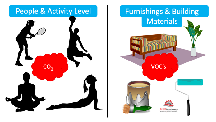
The sources of contamination in a space comes primarily from two type of sources: The first is the occupants in the space and their activities. The other is off-gassing from furnishings, building materials, adhesives, paints and glues used in construction. The amount of ventilation air to control the contaminants from these two sources is based on a calculation combining these two factors.
Sources of Contamination within Buildings.
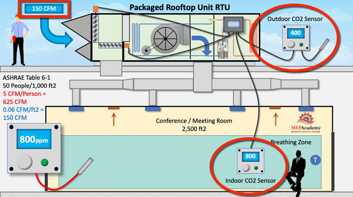
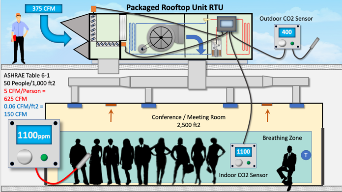
If you have a meeting room that is 2,500 square feet, ASHRAE table 6-1 would indicate that there would be 50 people for every 1,000 square feet, which means 125 people for this room at 5 CFM per person for a total of 625 CFM, plus another 0.06 CFM/ft2, adding another 150 CFM, for a total of 775 CFM of ventilation air required for this space.
But what happens when there is only one person in the room, when the system is designed for the maximum occupancy? The system will set the outside air damper at the minimum position, which is 150 CFM.
The Indoor CO2 sensor reads 800 parts per million, which is 400 higher than the Outdoor CO2 reading of 400 parts per million. The world’s average outdoor CO2 level is 419 parts per million.
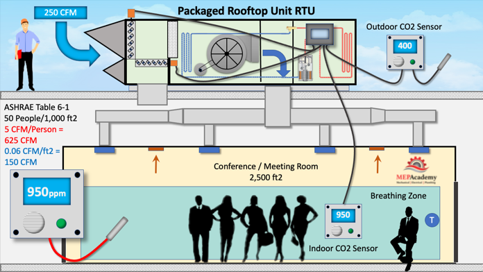
When a group of people enter the room, the CO2 sensor picks up the increase in carbon dioxide and now reads 950 parts per million. This information is sent to the main controller which sends a signal to the outside air damper to open proportionally. Now the outdoor air dampers opens wider and 250 CFM is entering the meeting room.
Demand Controlled Ventilation DCV
More people enter the meeting room causing CO2 levels to increase, and which now reads 1,100 parts per million. The same scenario occurs. A message is sent to the controller, and the outside air damper is again proportionally opened to accommodate the increase in CO2 levels. The outside air is now at 375 CFM.
DCV Increased CO2 Levels and Outside Air Damper Adjustments
Again, more people enter the room and the CO2 monitor picks up the increase in CO2 levels to 1250 ppm, and causing the Outside air damper to open further, sending 500 CFM of ventilation air into the space. (Image not shown)
DCV Maximum Ventilation Air at Maximum CO2 Setting.
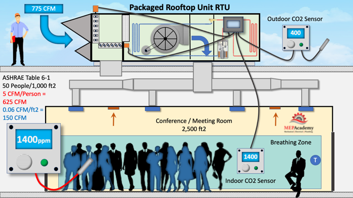
Another group of people attend the meeting and the CO2 level reaches 1400 ppm, outside air damper opens to the maximum setting based on the Ventilation Calculation of 775 CFM.
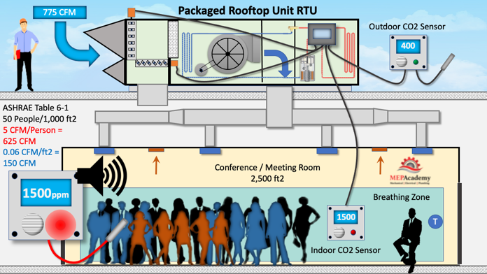
If additional people keep coming and the CO2 levels reaches 1500, an alarm is set off warning the occupants of an unhealthy level of CO2 in the room. Remember that this alarm can be set at a lower level.
Excessive CO2 causes alarm to make an Audible Noise and a Visible Flashing Light
This was just an example, we would hope that the Ventilation Air would be able to dilute the CO2 levels as designed without having to reach an alarm level, but if the outside air damper or it’s actuator weren’t functioning properly this would give you an early warning.
For ventilation purposes ASHRAE 62.1 Table 6-1 list various airflow rates required per person based on occupancy type. In a Gym a rate of 20 CFM per person is required, and in a meeting room its 5 CFM per person. The discrepancy is based on the anticipated activity level, in a meeting people are inactive, most likely sitting in a chair, while in a Gym, people are exercising, strenuously exerting themselves, raising their activity level and giving off more Carbon Dioxide.
The other component of the calculation is based on the square footage of the space, and this is to cover off-gassing and other building material contaminants. For the Meeting Room the area factor is 0.06 CFM/Ft2and for the Gym the area factor is 0.18 CFM/Ft2
Now will see when is Demand Controlled Ventilation required according to ASHRAE 90.1-2019, section 6.4.3.8 Ventilation Controls for High-Occupancy Areas.
Demand Control Ventilation (DCV) is required for spaces larger than 500 ft2 and with a design occupancy for ventilation of ≥25 people per 1,000 ft2 of floor area and served by systems with one or more of the following:
Air economizer
Automatic modulating control of outdoor air, and
Design outdoor airflow greater than 3,000 cfm
The Benefits of Using Demand Control Ventilation are
Improved health and employee satisfaction
Better indoor air quality with accurate CO2 monitoring