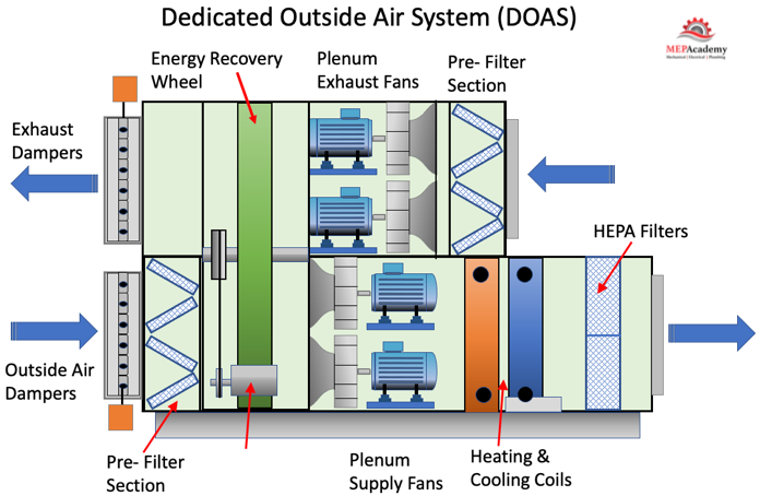
Dedicated Outside Air System DOAS. In this article we’ll learn how a Dedicated Outside Air Systems works, better known as a DOAS unit. We’ll learn the different methods of delivering outside air into spaces, and the various HVAC systems that work with a DOAS unit, like a VRF System, Water-Source Heat Pumps, Fan Coils and Chilled Beams.
If you prefer to watch our FREE YouTube version of this presentation, scroll to the bottom or Click the Link here. Dedicated Outside Air System Video.
Dedicated outside air systems are used to condition all ventilation air brought into the building for the health of the occupants and as mandated by code and set out in ASHRAE Standard 62.1. The outside air is either served directly to the space or in collaboration with a local HVAC system.
Standard VAV Air Handler
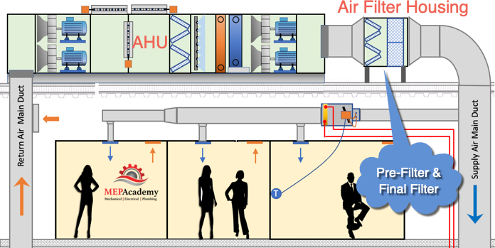
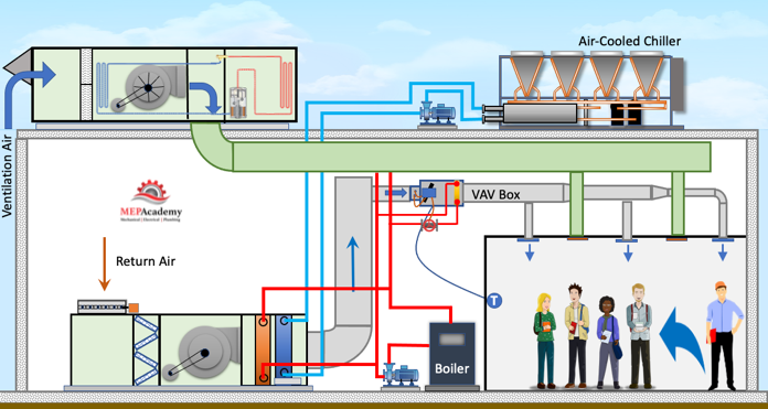
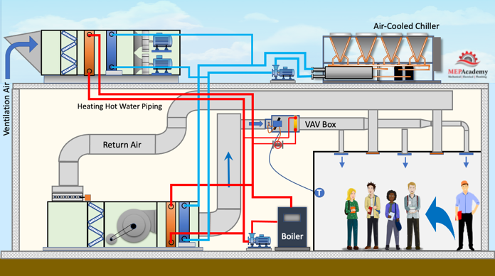
Before we add a Dedicated Outside Air Unit, let’s look at how ventilation air is normally brought into a commercial building using an air handling unit. This air handler mixes outside air with return air before entering the filter bank, and then through the fan and a Chilled Water coil served by a roof mounted air-cooled chiller.
The important thing to note is that the air handler and chiller are sized to treat all the latent heat coming in for ventilation and internal latent loads, in addition to the sensible load. The chilled water coil in the air handler is sized to provide latent and sensible cooling.
DOAS serving a VAV Air Handler
We can decouple the latent load from the sensible load by adding a DX DOAS unit, then the Air Handlers Chilled Water coil can be downsized, including the chiller, pump, and piping. This savings is offset by the addition of another piece of equipment, the Dedicated Outside Air System, which is dedicated to treating the ventilation air in an indirect or direct configuration, which we’ll discuss shortly.
If we install a DX Dedicated Outside Air Unit on the roof to handle the ventilation air and remove the outside air louver and duct from the indoor air handler, then all the latent load for the ventilation air will be handled by the DOAS unit.
Then we install sheet metal ductwork to connect the ventilation air from the DOAS unit indirectly to the space by connecting to the back of the Air Handler. This is considered an Indirect Method of providing Ventilation air, as the air is not delivered directly to the space, but through another piece of equipment.
Since the Dedicated Outside air unit is handling all of the load for the ventilation air, the chiller can be reduced in size, along will the air handler cooling coil. So we’ll remove this large air-cooled chiller and install a smaller one.
Now we’ll remove the indirect ventilation ductwork and connection the DOAS ventilation air directly to the space without going through the air handler.
One of the issues that the DOAS resolves better than a recirculating VAV systems, is that of delivering the proper amount of ventilation air to each space or zone. A VAV air handler can often over ventilate a highly populated space.
Two Common Methods of DOAS Unit Air delivery
The two most common ways of delivery ventilation air to a space from a DOAS unit is either directly to the space or to the intake of the Air Handler or zone level HVAC equipment. There are variations of these methods but these two represent the theory well enough. When delivering the air directly to the space the air can be constant volume or variable volume.
When the DOAS delivers the ventilation air directly to the air handler or terminal HVAC unit, the latent load is completely handled by the DOAS unit, while the Air Handling Unit or Terminal HVAC equipment will handle the sensible load.
Chilled Water DOAS
DOAS with Chilled Water Coil Cooling. We can also keep the same size chiller and use the extra capacity to feed a chilled water coil located within a DOAS unit. The Air handler’s cooling coil can be reduced as it doesn’t have to handle the latent load from the incoming ventilation air.
The DX DOAS unit can be removed and a Chilled Water DOAS added to handle the ventilation air. This will require the connection of heating hot water piping to the unit as well as chilled water piping. Since all the load for the ventilation air is being served by the chilled water, the chiller needs to be upsized.
A larger chiller is put on the roof to feed the load of the DOAS unit and the Air Handling unit. Sheet metal ductwork is used to feed the spaces directly. One of the main differences between this Chilled Water DOAS unit and the DX DOAS unit is in the method they produce dehumidification and cool air.
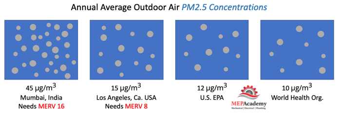
The DOAS unit will reduce indoor CO2 levels while removing excess humidity and condensation, which reduces sick building syndrome. The DOAS doesn’t recirculate indoor air back through the unit, so the air is always fresh, that is if the outside air is better than the indoor air. If the quality of outdoor air isn’t of the best quality, additional filtration can be added to the unit.
DOAS with Chilled Beams
Another system served by the Dedicated Outside Air Units is one with Chilled Beams. Chilled beams are considered passive or active. An Active Chilled Beam is what we are using to cool these spaces. They contain a coil or heat exchanger in a housing suspended above the floor.
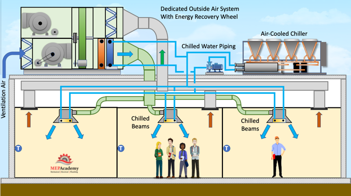
A Dedicated Outside Air Unit with an Energy Recovery Wheel is used with these chilled beams. The Energy Recover wheel is used to capture energy from the air being exhausted from the space, and returning this energy to the air entering the unit. Remember the DOAS unit is 100% outside air, so that means the exhaust air volume needs to be close to the quantity of ventilation air coming into the building to avoid over pressurizing the spaces.
Energy Recovery
Energy recovery is the process of exchanging sensible and/or latent heat between the exhaust air and outside air airstreams. Where extreme outdoor temperatures and relative humidifies exist, the use of energy recovery devices can increase energy savings by capturing the energy before its exhausted.
Using chilled beams will require the installation of a chiller, in this case, an air-cooled chiller mounted on the roof and piped to the chilled beams and the DOAS unit.
The ventilation air from the DOAS unit will pass through the Chilled Beam, inducing room air up into the center and through the cooling coil and back into the room. It’s important to keep the chilled water to these chilled beams above the dewpoint temperature to avoid condensation, as there are no drains used on these units.
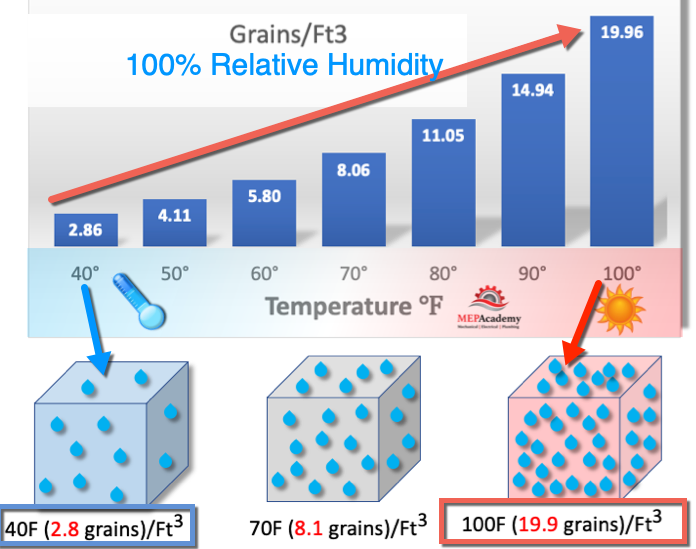
Typically, the greatest dehumidification loads are from ventilation air, as removing the moisture out of the outdoor air for ventilation requires latent heat. See our video on humidification for additional explanations of humidity.
The DOAS unit can provide heating, cooling, humidifying, and dehumidifying. The main purpose of a DOAS is to provide ventilation air for acceptable indoor air quality and to offset exhaust air used for bathrooms or other purposes.
DOAS with Fan Coils
Removing the chilled beams and redoing the ventilation duct and chilled water piping we can install a couple of fan coil units with connection to the chilled water system is another option. The ventilation air from the DOAS unit is indirectly connected to the space by connecting it to the return air plenum on the fan coil. A supply air grille can be installed on the ceiling to duct the ventilation air directly to the space.
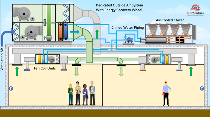
Using 4-pipe fan coils with a DOAS unit will separate the latent load from the sensible load. The DOAS will handle the latent load, while the fan coil units will handle the sensible load. The DOAS can deliver the supply air temperature low enough to pick up the additional room latent load also.
DOAS with a VRF System
DOAS units are often used with VRF Systems. Here we have an VRF Outdoor Unit installed on the roof. We have a ducted VRF Fan Coil unit, A VRF Ceiling Cassette and a VRF Wall Mounted fan coil. The outdoor unit will be connected to the indoor VRF fan coils using refrigerant piping. Here is a simple VRF Heat Pump system, which could also be used with a VRF Heat Recovery System.
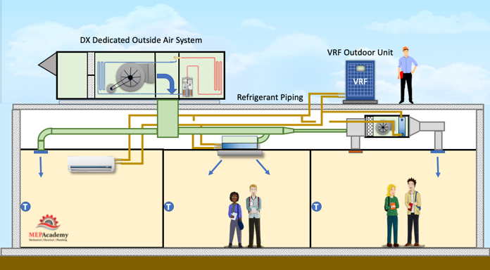
The Dedicated Outdoor Air System is connected directly to the space for the VRF Wall Mounted Cassette, and ducted indirectly to the VRF Ceiling Cassette and the VRF Concealed Ducted Fan Coil unit. This takes the burden of treating the ventilation air off of the VRF fan coils, which will handle the room load.
The DOAS can provide heating and cooling of the outdoor air provided for ventilation. Conditioning outdoor air is energy intensive and methods need to be adopted to avoid providing more outside air than is required by the spaces served.
The DOAS will remove the moisture or latent heat and sensible heat from the ventilation air, allowing any downstream equipment to focus on the space sensible load only.
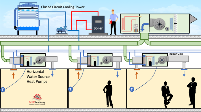
DOAS with Water Source Heat
Benefits of Increased Ventilation Rates
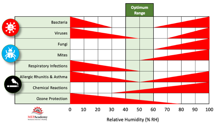
ASHRAE articles have often touted the benefits of increased ventilation as an increase in employee production, a decrease in absenteeism, and increased learning abilities. Building materials, furniture, carpet, paint and the various adhesives and chemicals used in construction are constantly off-gassing, filling the air with VOC’s (Volatile Organic Compounds), plus the CO2 given off from occupants adds additional pollutants. By increasing the ventilation rate, this issues can be minimized. Another benefit that has recently shed more light on the importance of bringing additional outside air into buildings has been the spread of various viruses, and that dilution is needed along with the proper Relative Humidity to reduce the infection rate.
Benefits of a DOAS System
- Decoupling the Latent and Sensible loads, gives better of latent heat to the exclusively focused DOAS unit. This also allows the use of high efficiency HVAC mostly sensible only units.
- Better accuracy on delivering the required ventilation air when compared to a central VAV air handler with various zones.
- Can be configured to control dewpoint and provide good Humidity Control
Latent Loads
The Dedicated Outside Air System DOAS unit will provide for the removal of the latent load which consist of the outside air. In addition to the latent load of the ventilation air, there is latent loads from the people in the building, infiltration into the building and various processes or equipment generated latent heat. When the wind blows it finds its ways into the building through cracks and openings in the building structure.
Reheating Outside Air to Avoid Over Cooling
Reheating the air using an energy recovery heat exchanger should only be done to prevent over cooling. You don’t want to waste energy heating up the air that was just cooled down. If reheating is required, then using zone level heating would be more efficient. It’s better to reheat only those zones requiring it, than to reheat at the air handler level that feeds all zones.
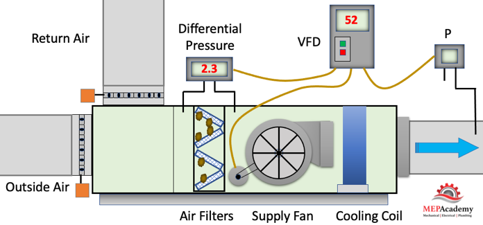
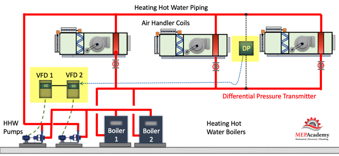
Variable Speed Drives on Zone Level Equipment (In-Direct OSA)
If the Dedicated Outdoor Air System feeds the zones directly without going through the zone level equipment, then any variable speed drive used at the zone level won’t affect the quantity of ventilation air delivered to the space. This allows the zone level equipment to cycle its volume, or shutoff completely without affecting the volume of outside air delivered to the space.
If the ventilation air is delivered directly to the zone level equipment than when the VFD slows down the fan, the amount of outside air will be affected.
With the addition of Pressure Independent Flow Measuring Dampers at the terminal units, the volume of ventilation air can remain unaffected by the VFD located in the termina units or the Dedicated Outside Air System DOAS.
The ability of the DOAS unit to adjust energy usage when demand is low is a great energy saving feature.
Ratio of Outside Air to Exhaust Air – Energy Recovery
When adding an energy recovery device to the DOAS unit, make sure that the utilization rate remains high. This is the ratio between the amount of outside air brought into the building versus the amount of exhaust going through the DOAS. If your supplying 10,000 CFM of outside air through the DOAS, and exhausting only 5,000, then you have a low ratio of 50%. (5,000/10,000).
Try to centralize the exhaust so it goes through the DOAS heat recovery heat exchanger to increase the ratio of exhaust to intake air.
ASHRAE
ASHRAE 62.1-2019 allows the use of bathroom exhaust as part of the exhaust energy to be captured.
Private and public toilet areas are designated as a Class 2 air stream which is subject to the recirculation requirements of ASHRAE 62.1. The higher the Class number the more restrictive it is to recirculate the air up in class. Bathroom exhaust air is a class 2 air which is prohibited from being recirculated up to a Class 1 air stream (ASHRAE 62.1-2019, 5.18.3.2.5).
5.18.3.2.5 Class 2 air shall not be recirculated or transferred to Class 1 spaces.
Class 1 air can be classrooms, meeting rooms, breakrooms, bedrooms, most public assembly areas and the supermarket. ASHRAE allows an exception for energy recovery devices. The exception allows for a maximum of 10% of class 2 air versus the total ventilation air through the DOAS. If you have a 10,000 cfm DOAS, then 1,000 CFM can be from a class 2 source.
Exception to 5.18.3.2.5: When using any energy recovery device, recirculation from leakage, carryover, or transfer from the exhaust side of the energy recovery device is permitted. Recirculated Class 2 air shall not exceed 10% of the outdoor air intake flow.
In cold winter climates, a preheater Is used on the OSA intake right before the heat recovery equipment so as to prevent frost from building up on the equipment.
When ASHRAE 90.1-2019 requires energy recovery, then the options are to use heat exchangers, heat pipes, run-around coils
ASHRAE 90.1-2019 Energy Standard
Minimum energy standards from ASHRAE 90.1-2019 are shown for a DOAS in Table 6.8.1-14 “Electrically Operated DX-DOAS Units, Single-Packaged and Remote Condenser, with Energy Recovery — Minimum Efficiency Requirements”
Air-Side Economizer
When calculating the size of the DOAS its important to consider the CFM required for any air-side economizer. If the DOAS unit only covers the minimum ventilation requirements, then its most likely not going to be able to provide the air flow (CFM) required when the air handlers or terminal units go into economizer mode.
Cooling Coils
Large capacity coils can be provided for additional dehumidification by allowing more air to coil contact to have a greater chance of reaching the dewpoint temperature.
HeatingHeating can be provided by gas, electric, hot water, or a heat pump. With the various fuel types, there are options for modulating the amount of heat, such that some larger gas units can have a turn down ration of 20:1, and electric heat with multiple stages where electric heating is allowed. The gas can be modulated to provide a consistent supply air temperature.
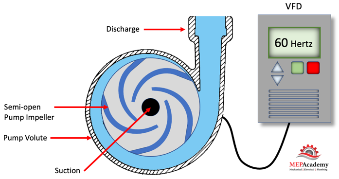
Variable Speed Compressors
DX DOAS units can be provided with Variable Speed Compressors to modulate cooling capacity and provide consistent supply air temperature. When the demand for cooling is reduced, variable speed compressors can save energy by reducing their speed. Units can come with standard scroll compressors, digital compressors or VFD controlled scroll compressors. Larger units could have dual circuits.
Supply Fans
DOAS units can be provided with ECM supply fans or driven by a VFD. Plenum supply fans are common.
Dew Point Calculations
Determining the dewpoint at various locations within the system is critical for controlling the indoor environment. If the dewpoint remains too high then mold and bacteria growth can occur, or if too low, then energy can be wasted cooling the air.
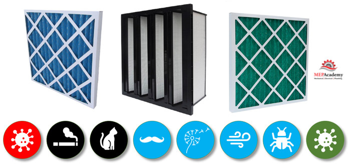
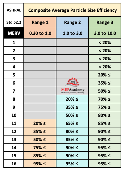
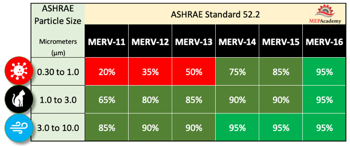
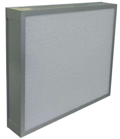
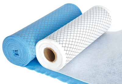
Filters
Filters are available in various MERV ratings from MERV-8 and above.