As the HVAC industry continues to embrace cutting-edge technology, having the right tools is more important than ever. Every technician needs tools that are reliable, efficient, and designed to tackle modern HVAC challenges. Whether you’re a seasoned pro or just starting out, these top 10 HVAC tools are must-haves for your toolkit.
If you prefer to watch the video of this article, then scroll to the bottom.
1. Fieldpiece SM480V Digital Manifold
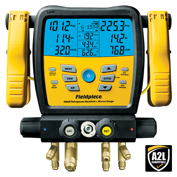
This manifold provides precise refrigerant measurements and live data logging. With wireless connectivity and temperature-compensated sensors, it simplifies diagnostics and charging. The data logger stores up to 9 jobs internally and has a USB port for easy download. This tool saves time while ensuring accuracy, making it indispensable for technicians. Checkout the Fieldpiece SM480
2. Fluke 902 FC HVAC Clamp Meter
This clamp meter offers true-RMS measurements, temperature readings, and capacitance testing, featuring Fluke Connect wireless technology, it’s designed to boost productivity for HVAC technicians in the field. Its rugged design ensures reliability in tough environments, helping technicians diagnose and resolve electrical issues efficiently. Checkout the Fluke 902
3. Milwaukee M12 FUEL Compact Vacuum
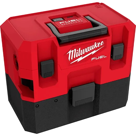
This is a lightweight, 12-volt cordless vacuum with powerful suction and a compact design that’s easy to store. It comes equipped with a flexible hose, crevice tool, utility nozzle, wall mount, and a certified HEPA filter, making it a reliable tool for efficient clean-up. Ideal for cleaning condensate lines and blower compartments, it enhances job site cleanliness and professionalism. Checkout the Milwaukee M12
4. Testo 550s Smart Digital Manifold
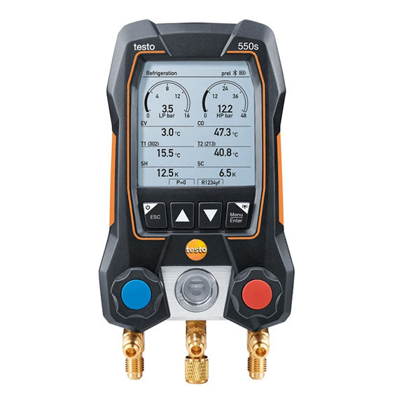
With Bluetooth integration and a compact design, the Testo 550s allows real-time data sharing and easy refrigerant management. Effortlessly view all results with the large, easy-to-read graphic display. This comprehensive kit is perfect for commissioning, servicing, and maintaining refrigeration, air conditioning systems, and heat pumps. Checkout the Testo 550s
5. NAVAC NRDD Recovery Machine
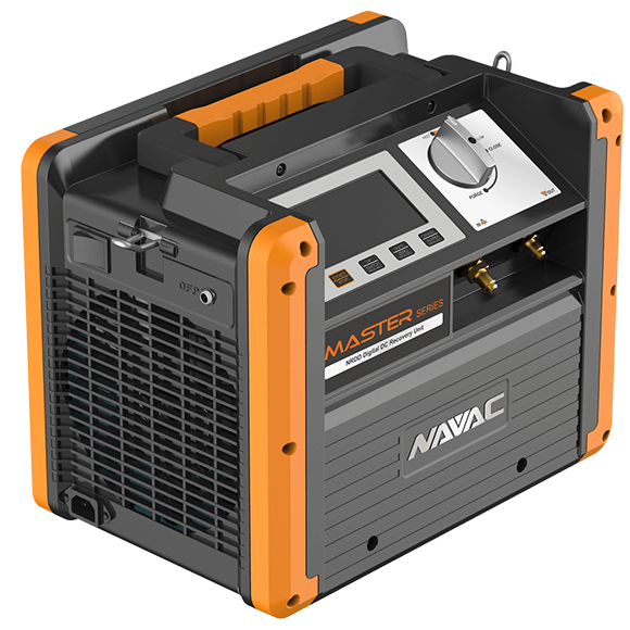
This recovery machine features a large backlit display and a dual-cylinder compressor for rapid refrigerant recovery. Lightweight and efficient, it speeds up the job while ensuring environmental compliance. Compatible with all commonly used refrigerants, the NRDD recovery unit is the ideal choice for reliable and versatile refrigerant recovery. Checkout the NAVAC Recovery Machine
6. Klein Tools ET310 AC Circuit Breaker Finder
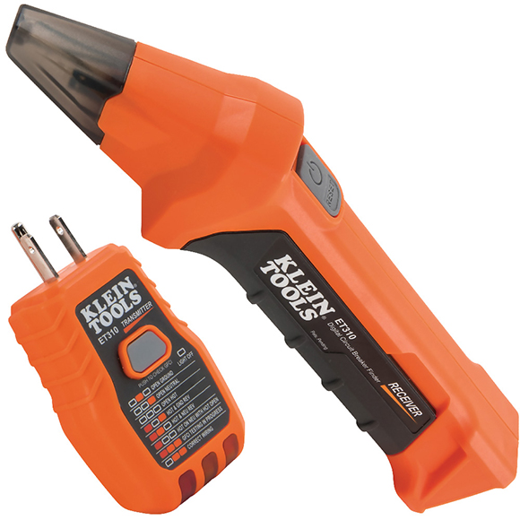
This AC Circuit Breaker Finder quickly and accurately identifies the correct circuit breaker for an outlet or fixture. It includes a transmitter that connects to the outlet or fixture and a receiver to scan the panel for the breaker. Clear visual and audible signals on the receiver when the correct breaker is found. Its accuracy reduces troubleshooting time, making electrical diagnostics more straightforward and efficient. Checkout the Klein Circuit Breaker Finder
7. REED Instruments R2330 Infrared Thermometer
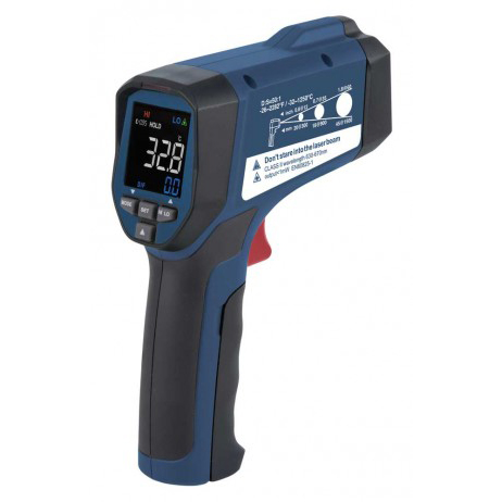
This infrared thermometer provides accurate surface temperature readings without contact. Its bright color display ensures easy readability in both sunlight and low-light conditions, while tri-color LEDs indicate temperature status, with built-in laser pointer for precise targeting. It’s perfect for identifying inefficiencies like duct leaks and hot spots in either Fahrenheit or Celsius readings. Checkout REED Infrared Thermometer
8. CPS Products Pro-Set 2-Valve Manifold
Specifically designed for modern refrigerants, including the R32, R410A, and R454B class A2L refrigerant, the CPS Products Pro-Set offers durability and precision. It’s a must-have for technicians working with next-generation systems. Checkout the CPS Manifolds
9. Hilti DX 5 Powder-Actuated Fastening Tool
The DX 5 simplifies fastening into concrete and steel, offering consistent performance. It saves time on installations and enhances job site productivity. Checkout Hilti Tools
10. Bosch GLM50C Bluetooth Laser Measure
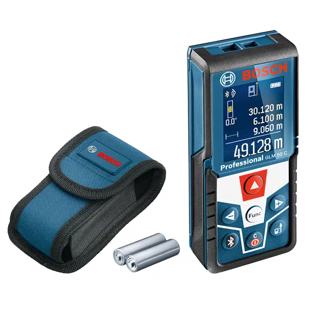
Accurate measurements are vital in HVAC installations and retrofits. This laser measure delivers precise laser measurements, Bluetooth connectivity, and app integration for easy data storage and sharing. Smart Measuring and Documentation Made Easy. It’s ideal for planning installations and ensuring accurate layouts with minimal effort. Checkout the Bosch Laser Tool
Investing in high-quality tools is essential for HVAC technicians to stay efficient and competitive. These top 10 tools not only make your job easier but also ensure you deliver top-notch service. As technology advances, having the best tools at your disposal will set you apart in the ever-evolving HVAC industry. Equip yourself for success in 2025 with these must-have tools!