In this article we’ll answer a question that we get all the time. What filter, if any, can filter out the SARS-CoV-2 virus which leads to COVID-19, the disease? We’ll show you how efficient the different air filters are at filtering out various items for asthma and allergy sufferers, and the virus that leads to COVID-19.
If you prefer to watch the Video of this presentation, then scroll to the bottom or click on the following link. Air Filters vs COVID-19
The ability of an air filter to remove microorganism, dust, pollen, dust mites, mold spores, pet dander, bacteria and viruses is indicated by a numerical value. This number, which is indicated as a MERV rating, states the filter’s efficiency at removing various sizes of these items. We’ll show you which filters, if any, work the best to protect you from these potentially harmful organisms.
MERV Rating
Minimum Efficiency Reporting Values, or MERVs, indicate the filter’s ability to capture larger particles, those 0.3 microns and larger. The higher the numerical rating, the greater the air filter is at removing particles from the air stream. A MERV-13 is better than a MERV-11 filter at removing particles, but how good are they against bacteria and a very small virus that leads to COVID-19.
Virus and Bacteria Removal
According to ASHRAE, research has shown that the particle size of the SARS-CoV-2 virus that leads to COVID-19 is around 0.1 microns. This is much smaller than what may be picked up by these air filters. As this chart shows, the virus lives in the invisible region, while others like dust, cat dander and human hair are visible to the human eye.
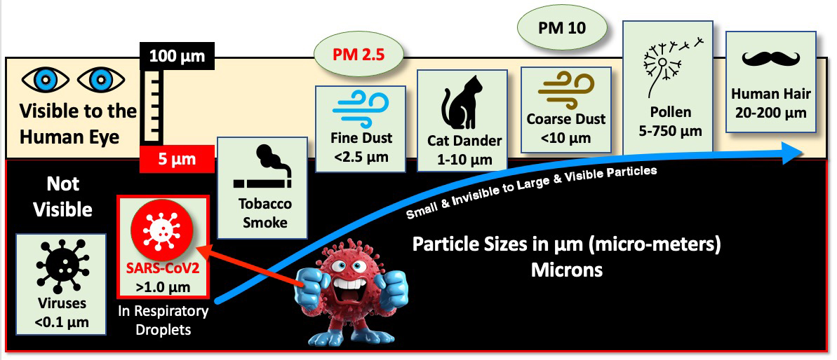
Luckily, the SARS-CoV-2 virus doesn’t travel through the air own its own. It rides on respiratory droplets and droplet nuclei (dried respiratory droplets) that are predominately 1 micron in size and larger. These filters have various efficiencies at capturing the viruses that are in the 1-to-3-micron range according to ASHRAE.
ASHRAE
As the chart shows, ASHRAE recommends using a minimum of a MERV 13 filter, which is at least 85% efficient at capturing particles in the 1 to 3-micron size range. A MERV 14 filter is at least 90% efficient at capturing those same particles. High-efficiency particulate air (HEPA) filters are even more efficient at filtering human-generated infectious aerosols.
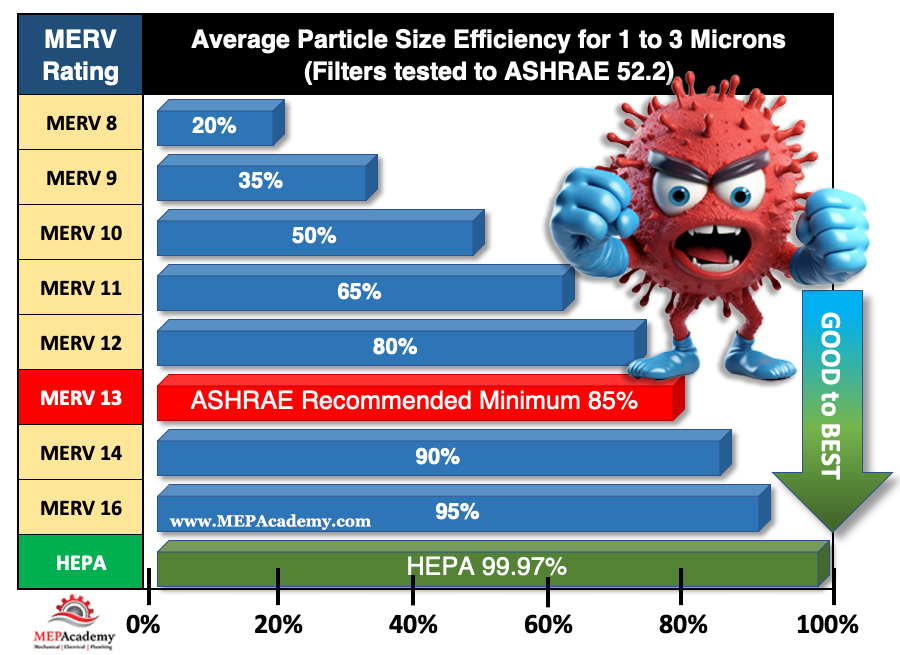
By definition, a HEPA air filter must be at least 99.97% efficient at capturing particles 0.3 micron in size. This 0.3-micron particle approximates the most penetrating particle size (MPPS) through the filter. HEPA filters are even more efficient at capturing particles larger AND smaller than the MPPS. Thus, HEPA air filters are more than 99.97% efficient at capturing airborne viral particles associated with SARS-CoV-2 which leads to COVID-19.
Checkout these HEPA Filters for your Home or OfficeHEPA filters can capture and trap microorganisms, including viruses and bacteria, helping to reduce the risk of respiratory infections. So, if possible, use the highest MERV rated air filter with your system, or get a portable HEPA air filter for your room or office. HEPA filters are the most efficient at capturing small microorganisms like the SARS-CoV-2 virus.
Where are HEPA Filters used?
HEPA air filters are used in residential, commercial, and industrial facilities. In homes there are portable types that can be moved from room to room, and others that can be installed in a central air conditioning system serving the whole house.
HEPA air filters are also used along with ULPA filters in cleanrooms, labs, and other spaces requiring a very clean environment.
Asthma and Allergy Management
For individuals with asthma, HEPA filters help reduce asthma triggers like airborne irritants and respiratory allergens. According to the Asthma and Allergy Foundation of America (AAFA), nearly 26 million people have asthma in the United States. There are 4.8 million children under the age of 18, and nearly 21 million adults suffering from asthma. On average, 10 people in the unites States die every day from asthma. A total of 3,517 deaths in 2021.
According to the AAFA over 100 million people each year in the United States experience various types of allergies. Allergies are the sixth leading cause of chronic illness in the U.S. HEPA filters are highly effective at removing allergens such as pollen, dust mites, and pet dander, providing relief to allergy sufferers.
Editorial Process:
Some of the links in this article may be affiliate links, which can provide compensation to the MEPAcademy at no cost to you if you decide to purchase. Our reviews and articles are made by an industry professional experienced in the engineering and construction of commercial buildings.