The Importance of Technology in the Construction Industry
This is the sixth article in our series on what it takes to create and sustain a successful construction contracting company. See why Technology in Construction is one of the key factors for creating a successful construction company. Technology plays a crucial role in the construction industry, revolutionizing various aspects of the entire construction lifecycle. Here are some key areas where technology has immense importance in the construction industry.
If you prefer to watch the video version of this presentation then scroll to the bottom or click on the following link. Technology in Construction
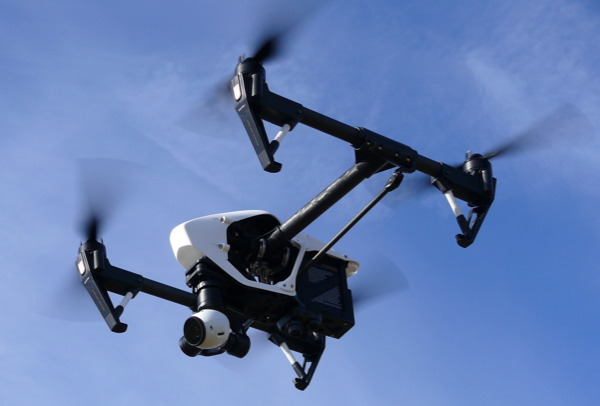
Drones
Unmanned aerial vehicles (UAVs) or drones are used for aerial surveys, site inspections, and data collection. Drones equipped with cameras and sensors can capture high-resolution images, videos, and 3D maps of construction sites, assisting in site analysis, progress monitoring, and quality control. Drones also enhance safety by reducing the need for workers to access hazardous areas manually.
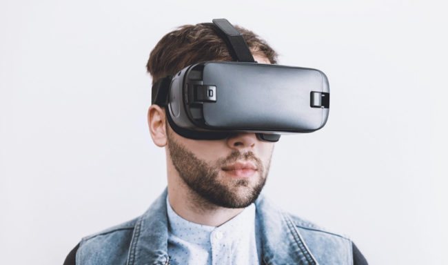
Virtual and Augmented Reality
Virtual reality (VR) and augmented reality (AR) technologies are transforming the construction industry. VR allows stakeholders to experience immersive virtual walkthroughs of buildings before they are constructed, facilitating design reviews and client engagement. AR overlays digital information onto the physical environment, aiding in on-site visualization, quality control, clash detection, and maintenance.
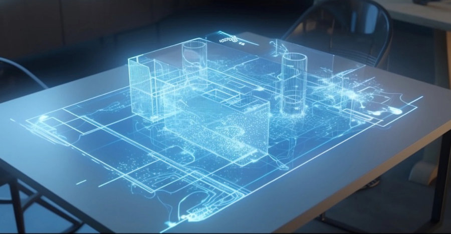
Design and Visualization
Technology enables architects and engineers to create sophisticated 3D models and visualizations, allowing stakeholders to better understand and review the proposed structures before construction begins. This helps identify design flaws, optimize efficiency, and enhance collaboration.
Internet of Things (IoT)
IoT devices and sensors are deployed on construction sites to monitor and collect data on various parameters, such as equipment performance, energy usage, environmental conditions, and worker safety. IoT data enables real-time monitoring, predictive maintenance, and data-driven decision-making.
Wearable Technology
Wearables, such as smart helmets, vests, and glasses, incorporate sensors and communication capabilities. They provide real-time data on worker location, vital signs, fatigue levels, and exposure to hazardous conditions, enhancing safety and health management on construction sites.
Robotics and Automation
Robotics and automation technologies improve construction efficiency and productivity. Robotic systems can perform repetitive tasks, such as bricklaying, concrete pouring, and material handling, with precision and speed. Automation is also used for off-site prefabrication, reducing manual labor, and enhancing quality control. These technologies improve safety, productivity, and efficiency, while also addressing labor shortages in the industry.
Prefabrication and Modular Construction
Technology has advanced prefabrication and modular construction techniques. Off-site manufacturing of building components allows for better quality control, faster construction timelines, and reduced waste. Prefabrication also enables higher precision and cost savings, particularly in repetitive construction processes, and improves safety by minimizing on-site work.
3D Printing
3D printing, or additive manufacturing, is used to create building components and prototypes with precision and efficiency. It enables complex geometries, reduces material waste, and allows for customization. 3D printing is often employed in the production of architectural models, structural components, and prefabricated elements.
Building Information Modeling (BIM)
BIM is a digital representation of a building’s physical and functional characteristics. It integrates various data sources, including architectural designs, structural analysis, and material specifications, into a single platform. It facilitates integrated project management, allowing architects, engineers, contractors, and other stakeholders to collaborate and share information seamlessly. BIM improves coordination, reduces errors, enhances efficiency, and enables better decision-making throughout the project lifecycle.
Construction Management Software
Construction management software provides tools for project planning, scheduling, resource allocation, cost estimation, document management, and collaboration. These software solutions help streamline project workflows, enhance communication, and improve overall project management. Real-time project tracking and communication tools facilitate better collaboration between teams, subcontractors, and clients. Real-time updates and mobile applications allow project managers to monitor construction activities on-site and address issues promptly. This leads to improved productivity, reduced delays, and enhanced project control.
Sustainability and Green Construction
Technology plays a vital role in promoting sustainable construction practices. Energy modeling software helps optimize building designs for energy efficiency. IoT devices and sensors enable real-time monitoring of energy consumption, water usage, and indoor air quality. Additionally, technologies like green materials, renewable energy systems, and smart building management systems contribute to reducing the environmental impact of construction projects. Green building technologies, including solar panels, energy-efficient systems, smart lighting, and water conservation techniques, help minimize environmental impact and reduce long-term operational costs.
Data Analytics and Automation
The construction industry generates vast amounts of data, and technology enables its collection, analysis, and utilization. Data analytics provides valuable insights into project performance, productivity, and cost management, enabling informed decision-making. Automation and robotics streamline repetitive tasks, increasing efficiency and productivity.
Mobile Applications
Mobile apps are extensively used in the construction industry for project management, communication, and on-site operations. These apps facilitate access to project documents, drawings, and schedules, enable collaboration among team members, and provide real-time updates from the field.
Safety and Risk Management
Technology plays a crucial role in improving safety on construction sites. Wearable devices, such as smart helmets and vests, can monitor workers’ vital signs, detect hazards, and alert them to potential risks. Sensors and IoT (Internet of Things) devices enable real-time monitoring of safety parameters, such as air quality, temperature, and structural integrity, ensuring a safer working environment.
Construction Techniques and Equipment
Technology has revolutionized construction techniques and equipment. Advanced machinery, such as cranes, excavators, and robotic systems, enhance speed, precision, and safety in construction operations. Drones are used for aerial surveys, inspections, and monitoring construction sites, providing valuable data and reducing human risk.
These are just a few examples of the many technologies that are transforming the construction industry, improving productivity, reducing cost, improving safety, collaboration, and sustainability. Embracing these technological advancements allows construction companies to stay competitive, reduce cost, deliver better-quality projects in a timely manner, and adapt to the evolving needs of the built environment.
Contractor Success Series
- Estimating and Budget for Contractor Success.
- Strong Leadership for Contractor Success.
- Good Project Management for Contractor Success
- Skilled Workers for Contractor Success
- Construction Safety for Contractor Success
- Technology in Construction for Contractor Success.
- Financial Stability for Contractor Success.