Energy Valve. In this article we’ll learn how an Energy valve works, how it saves energy, where it is used and how it can prevent the low Delta-T syndrome.
If you prefer to watch the YouTube Video of this presentation, then scroll to the bottom or click on this link. Energy Valve Video
Here is the Energy valve. It has an ultrasonic Flow meter that measure the flow (GPM) going through the piping. This gives us the GPM in our equation. Then we have temperature sensors on the supply and return piping to our heat exchanger or coil. This will give us the Delta-T in our equation.
With these two values the Energy Valves onboard controls logic can determine the energy, or the Q in our equation which is the BTU/Hour. This consumption of energy can be used to bill a tenant for their use of the chilled water or heating hot water system.
To adjust the flow or GPM, the Energy Valve will modulate the Actuator on the Control Valve. The GPM is adjusted to reach the Delta-T setpoint of the Energy Value.
We can install these Energy Valves on the Coils feeding an Air Handling unit, and install Temperature sensors and the connecting cabling.
We can look at the difference between maintaining Delta-T with an Energy Valve and the traditional system. We converted our formula to solve for GPM. Using a heat load of 120,000 Btu/Hr. or 10-Tons, we get 15 GPM if the Energy Valve is maintaining the Delta-T at a setpoint of 16 degrees. The traditional system has slipped to a 6 degree Delta-T, requiring 40 GPM to get the required heat transfer. This additional GPM causes an increase in pump energy, and would require larger piping. The size of the piping for the Energy valve system would be 1-1/4”, while the traditional system would require 2” to match the same heat transfer quantity.
If the heat load drops to 36,000 Btu/Hr., which is 30% of the peak design load, then we get 4.5 GPM through the Energy Valve at a 16 degree Delta-T. The traditional system is requiring 12 GPM to get the required heat transfer. Saving energy requires managing the Delta-T through the heat exchanger so that the pumps and central plant equipment runs efficiently.
Air Handler Coils and Energy Valves
The Energy valve can be used with Air Handlers as shown here. The contractor installs the Energy Valve and a Temperature Sensor on the Chilled Water Supply piping. Connection can be made to a Building Management System for remote monitoring, data collection and programming.
Fan Coils and Energy Valves
The Energy Valve can be installed on Fan Coil Units also.
Chilled Beams and Energy Valves
The Energy Valve can be installed on Chilled Beams. The Valve can be installed on just about any coil or heat exchanger to manage Delta-T and avoid the Low Delta-T Syndrome.
Low Delta-T Syndrome
Tracking the Delta-T of the water being delivered to HVAC Coils is important in maintaining an efficient system. The valve tracks the current Delta-T and compares it to the set-point Delta-T to be maintained, making adjustments as required to keep it at minimum set-point or above. To increase the delta-T, the valve will throttle to lower the flow of water through the coil. This gives the water more time to transfer heat.
There is a large cost in electricity consumed to run chillers to make chilled water. This makes it important to use the energy consumption power of this water to its maximum ability, which will occur with a higher Delta-T. Higher Delta-T systems also use less pump energy, as more energy is removed in a smaller volume of water. A delta-T of 16 is much better than a delta-T of 5 or less. The energy valve manages Delta-T to maximize the energy use of the system. To avoid low flow situations, there is a minimum flow setting of 30% when using the Delta-T manager
If you have a low Delta-T then the water is passing through the coil to quickly, not allowing enough time for heat transfer to occur. By managing the delta-T, the energy valve can reduce the flow (GPM) through the coil allowing enough time for the water to consume heat from the heat exchanger. Better heat removal and increased efficiency.
Heat Removal and Increased Efficiency
If we look at the chilled water system serving a building, its purpose is to remove heat using as little energy as possible to do so. This requires that the chilled water carry as much heat as possible within each volume of water passing through the coil. In order to do this we need the water to increase in temperature as much as possible, this is indicated by the Delta-T, the difference in temperature between the chilled water supply and the return. A higher Delta-T requires less water to be pumped through the system, saving on pump energy.
In order to avoid providing too much flow to a coil or heat exchanger, an energy valve can ensure optimization of system flow. By measuring the temperature of the supply and return system water, whether chilled water or heating hot water, the onboard software can optimize flow. Using ultrasonic technology the energy valve measures the flow through the valve. There is an option for the sensing of a system with glycol circulating through the valve.
With the flow and the temperature of the supply and return water circulating through the valve, calculating the total energy is a simple formula.
Q = 500 x GPM x Delta-T
Building Management System Integration
The valve has the capability to connect using Modbus and BACnet protocols, in addition to the capability to connect securely to the internet. This allows for monitoring of temperatures and flows, which can be used to bill tenants for energy consumption.
The valve logs the energy consumption for up to 13 months on the valve or for indefinitely when connected to the cloud. The control range signal is set at the default of 2 – 10 VDC.
Demand Controlled Ventilation (DCV). In this presentation we’ll discuss Demand Controlled Ventilation, and the Controls used to manage the ventilation air. We’ll review the ASHRAE standards 62.1 (Ventilation) and 90.1 (Energy) and how they relate to ventilation. We’ll show you how to use the standards to calculate the required ventilation air rate (CFM) for a space.
If you prefer to watch the YouTube version of this presentation, scroll to the bottom or click on this link. Demand Controlled Ventilation Video
First will show you how a CO2 monitor works in a commercial building using a single zone HVAC system feeding a meeting room. Well show you what happens when the room is empty and what happens when there is too much CO2 in the space.
Sources of Contamination
The sources of contamination in a space comes primarily from two type of sources: The first is the occupants in the space and their activities. The other is off-gassing from furnishings, building materials, adhesives, paints and glues used in construction. The amount of ventilation air to control the contaminants from these two sources is based on a calculation combining these two factors.
If you have a meeting room that is 2,500 square feet, ASHRAE table 6-1 would indicate that there would be 50 people for every 1,000 square feet, which means 125 people for this room at 5 CFM per person for a total of 625 CFM, plus another 0.06 CFM/ft2, adding another 150 CFM, for a total of 775 CFM of ventilation air required for this space.
But what happens when there is only one person in the room, when the system is designed for the maximum occupancy? The system will set the outside air damper at the minimum position, which is 150 CFM.
The Indoor CO2 sensor reads 800 parts per million, which is 400 higher than the Outdoor CO2 reading of 400 parts per million. The world’s average outdoor CO2 level is 419 parts per million.
When a group of people enter the room, the CO2 sensor picks up the increase in carbon dioxide and now reads 950 parts per million. This information is sent to the main controller which sends a signal to the outside air damper to open proportionally. Now the outdoor air dampers opens wider and 250 CFM is entering the meeting room.
More people enter the meeting room causing CO2 levels to increase, and which now reads 1,100 parts per million. The same scenario occurs. A message is sent to the controller, and the outside air damper is again proportionally opened to accommodate the increase in CO2 levels. The outside air is now at 375 CFM.
Again, more people enter the room and the CO2 monitor picks up the increase in CO2 levels to 1250 ppm, and causing the Outside air damper to open further, sending 500 CFM of ventilation air into the space. (Image not shown)
Another group of people attend the meeting and the CO2 level reaches 1400 ppm, outside air damper opens to the maximum setting based on the Ventilation Calculation of 775 CFM.
If additional people keep coming and the CO2 levels reaches 1500, an alarm is set off warning the occupants of an unhealthy level of CO2 in the room. Remember that this alarm can be set at a lower level.
This was just an example, we would hope that the Ventilation Air would be able to dilute the CO2 levels as designed without having to reach an alarm level, but if the outside air damper or it’s actuator weren’t functioning properly this would give you an early warning.
For ventilation purposes ASHRAE 62.1 Table 6-1 list various airflow rates required per person based on occupancy type. In a Gym a rate of 20 CFM per person is required, and in a meeting room its 5 CFM per person. The discrepancy is based on the anticipated activity level, in a meeting people are inactive, most likely sitting in a chair, while in a Gym, people are exercising, strenuously exerting themselves, raising their activity level and giving off more Carbon Dioxide.
The other component of the calculation is based on the square footage of the space, and this is to cover off-gassing and other building material contaminants. For the Meeting Room the area factor is 0.06 CFM/Ft2and for the Gym the area factor is 0.18 CFM/Ft2
Now will see when is Demand Controlled Ventilation required according to ASHRAE 90.1-2019, section 6.4.3.8 Ventilation Controls for High-Occupancy Areas.
Demand Control Ventilation (DCV) is required for spaces larger than 500 ft2 and with a design occupancy for ventilation of ≥25 people per 1,000 ft2 of floor area and served by systems with one or more of the following:
Air economizer
Automatic modulating control of outdoor air, and
Design outdoor airflow greater than 3,000 cfm
The Benefits of Using Demand Control Ventilation are
Improved health and employee satisfaction
Better indoor air quality with accurate CO2 monitoring
Dedicated Outside Air System DOAS. In this article we’ll learn how a Dedicated Outside Air Systems works, better known as a DOAS unit. We’ll learn the different methods of delivering outside air into spaces, and the various HVAC systems that work with a DOAS unit, like a VRF System, Water-Source Heat Pumps, Fan Coils and Chilled Beams.
If you prefer to watch our FREE YouTube version of this presentation, scroll to the bottom or Click the Link here. Dedicated Outside Air System Video.
Dedicated outside air systems are used to condition all ventilation air brought into the building for the health of the occupants and as mandated by code and set out in ASHRAE Standard 62.1. The outside air is either served directly to the space or in collaboration with a local HVAC system.
Standard VAV Air Handler
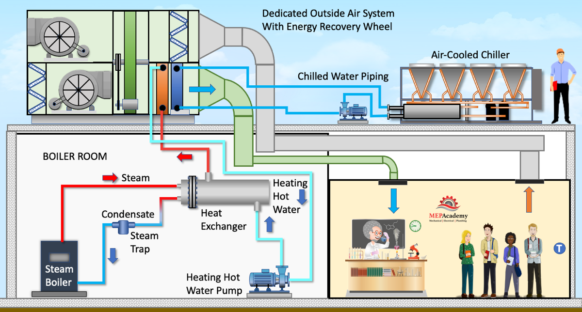
Before we add a Dedicated Outside Air Unit, let’s look at how ventilation air is normally brought into a commercial building using an air handling unit. This air handler mixes outside air with return air before entering the filter bank, and then through the fan and a Chilled Water coil served by a roof mounted air-cooled chiller.
The important thing to note is that the air handler and chiller are sized to treat all the latent heat coming in for ventilation and internal latent loads, in addition to the sensible load. The chilled water coil in the air handler is sized to provide latent and sensible cooling.
DOAS serving a VAV Air Handler
We can decouple the latent load from the sensible load by adding a DX DOAS unit, then the Air Handlers Chilled Water coil can be downsized, including the chiller, pump, and piping. This savings is offset by the addition of another piece of equipment, the Dedicated Outside Air System, which is dedicated to treating the ventilation air in an indirect or direct configuration, which we’ll discuss shortly.
If we install a DX Dedicated Outside Air Unit on the roof to handle the ventilation air and remove the outside air louver and duct from the indoor air handler, then all the latent load for the ventilation air will be handled by the DOAS unit.
Then we install sheet metal ductwork to connect the ventilation air from the DOAS unit indirectly to the space by connecting to the back of the Air Handler. This is considered an Indirect Method of providing Ventilation air, as the air is not delivered directly to the space, but through another piece of equipment.
Since the Dedicated Outside air unit is handling all of the load for the ventilation air, the chiller can be reduced in size, along will the air handler cooling coil. So we’ll remove this large air-cooled chiller and install a smaller one.
Now we’ll remove the indirect ventilation ductwork and connection the DOAS ventilation air directly to the space without going through the air handler.
One of the issues that the DOAS resolves better than a recirculating VAV systems, is that of delivering the proper amount of ventilation air to each space or zone. A VAV air handler can often over ventilate a highly populated space.
Two Common Methods of DOAS Unit Air delivery
The two most common ways of delivery ventilation air to a space from a DOAS unit is either directly to the space or to the intake of the Air Handler or zone level HVAC equipment. There are variations of these methods but these two represent the theory well enough. When delivering the air directly to the space the air can be constant volume or variable volume.
When the DOAS delivers the ventilation air directly to the air handler or terminal HVAC unit, the latent load is completely handled by the DOAS unit, while the Air Handling Unit or Terminal HVAC equipment will handle the sensible load.
Chilled Water DOAS
DOAS with Chilled Water Coil Cooling. We can also keep the same size chiller and use the extra capacity to feed a chilled water coil located within a DOAS unit. The Air handler’s cooling coil can be reduced as it doesn’t have to handle the latent load from the incoming ventilation air.
The DX DOAS unit can be removed and a Chilled Water DOAS added to handle the ventilation air. This will require the connection of heating hot water piping to the unit as well as chilled water piping. Since all the load for the ventilation air is being served by the chilled water, the chiller needs to be upsized.
A larger chiller is put on the roof to feed the load of the DOAS unit and the Air Handling unit. Sheet metal ductwork is used to feed the spaces directly. One of the main differences between this Chilled Water DOAS unit and the DX DOAS unit is in the method they produce dehumidification and cool air.
The DOAS unit will reduce indoor CO2 levels while removing excess humidity and condensation, which reduces sick building syndrome. The DOAS doesn’t recirculate indoor air back through the unit, so the air is always fresh, that is if the outside air is better than the indoor air. If the quality of outdoor air isn’t of the best quality, additional filtration can be added to the unit.
DOAS with Chilled Beams
Another system served by the Dedicated Outside Air Units is one with Chilled Beams. Chilled beams are considered passive or active. An Active Chilled Beam is what we are using to cool these spaces. They contain a coil or heat exchanger in a housing suspended above the floor.
A Dedicated Outside Air Unit with an Energy Recovery Wheel is used with these chilled beams. The Energy Recover wheel is used to capture energy from the air being exhausted from the space, and returning this energy to the air entering the unit. Remember the DOAS unit is 100% outside air, so that means the exhaust air volume needs to be close to the quantity of ventilation air coming into the building to avoid over pressurizing the spaces.
Energy Recovery
Energy recovery is the process of exchanging sensible and/or latent heat between the exhaust air and outside air airstreams. Where extreme outdoor temperatures and relative humidifies exist, the use of energy recovery devices can increase energy savings by capturing the energy before its exhausted.
Using chilled beams will require the installation of a chiller, in this case, an air-cooled chiller mounted on the roof and piped to the chilled beams and the DOAS unit.
The ventilation air from the DOAS unit will pass through the Chilled Beam, inducing room air up into the center and through the cooling coil and back into the room. It’s important to keep the chilled water to these chilled beams above the dewpoint temperature to avoid condensation, as there are no drains used on these units.
Typically, the greatest dehumidification loads are from ventilation air, as removing the moisture out of the outdoor air for ventilation requires latent heat. See our video on humidification for additional explanations of humidity.
The DOAS unit can provide heating, cooling, humidifying, and dehumidifying. The main purpose of a DOAS is to provide ventilation air for acceptable indoor air quality and to offset exhaust air used for bathrooms or other purposes.
DOAS with Fan Coils
Removing the chilled beams and redoing the ventilation duct and chilled water piping we can install a couple of fan coil units with connection to the chilled water system is another option. The ventilation air from the DOAS unit is indirectly connected to the space by connecting it to the return air plenum on the fan coil. A supply air grille can be installed on the ceiling to duct the ventilation air directly to the space.
Using 4-pipe fan coils with a DOAS unit will separate the latent load from the sensible load. The DOAS will handle the latent load, while the fan coil units will handle the sensible load. The DOAS can deliver the supply air temperature low enough to pick up the additional room latent load also.
DOAS with a VRF System
DOAS units are often used with VRF Systems. Here we have an VRF Outdoor Unit installed on the roof. We have a ducted VRF Fan Coil unit, A VRF Ceiling Cassette and a VRF Wall Mounted fan coil. The outdoor unit will be connected to the indoor VRF fan coils using refrigerant piping. Here is a simple VRF Heat Pump system, which could also be used with a VRF Heat Recovery System.
The Dedicated Outdoor Air System is connected directly to the space for the VRF Wall Mounted Cassette, and ducted indirectly to the VRF Ceiling Cassette and the VRF Concealed Ducted Fan Coil unit. This takes the burden of treating the ventilation air off of the VRF fan coils, which will handle the room load.
The DOAS can provide heating and cooling of the outdoor air provided for ventilation. Conditioning outdoor air is energy intensive and methods need to be adopted to avoid providing more outside air than is required by the spaces served.
The DOAS will remove the moisture or latent heat and sensible heat from the ventilation air, allowing any downstream equipment to focus on the space sensible load only.
DOAS with Water Source Heat
Benefits of Increased Ventilation Rates
ASHRAE articles have often touted the benefits of increased ventilation as an increase in employee production, a decrease in absenteeism, and increased learning abilities. Building materials, furniture, carpet, paint and the various adhesives and chemicals used in construction are constantly off-gassing, filling the air with VOC’s (Volatile Organic Compounds), plus the CO2 given off from occupants adds additional pollutants. By increasing the ventilation rate, this issues can be minimized. Another benefit that has recently shed more light on the importance of bringing additional outside air into buildings has been the spread of various viruses, and that dilution is needed along with the proper Relative Humidity to reduce the infection rate.
Benefits of a DOAS System
Decoupling the Latent and Sensible loads, gives better of latent heat to the exclusively focused DOAS unit. This also allows the use of high efficiency HVAC mostly sensible only units.
Better accuracy on delivering the required ventilation air when compared to a central VAV air handler with various zones.
Can be configured to control dewpoint and provide good Humidity Control
Latent Loads
The Dedicated Outside Air System DOAS unit will provide for the removal of the latent load which consist of the outside air. In addition to the latent load of the ventilation air, there is latent loads from the people in the building, infiltration into the building and various processes or equipment generated latent heat. When the wind blows it finds its ways into the building through cracks and openings in the building structure.
Reheating Outside Air to Avoid Over Cooling
Reheating the air using an energy recovery heat exchanger should only be done to prevent over cooling. You don’t want to waste energy heating up the air that was just cooled down. If reheating is required, then using zone level heating would be more efficient. It’s better to reheat only those zones requiring it, than to reheat at the air handler level that feeds all zones.
Variable Speed Drives on Zone Level Equipment (In-Direct OSA)
If the Dedicated Outdoor Air System feeds the zones directly without going through the zone level equipment, then any variable speed drive used at the zone level won’t affect the quantity of ventilation air delivered to the space. This allows the zone level equipment to cycle its volume, or shutoff completely without affecting the volume of outside air delivered to the space.
If the ventilation air is delivered directly to the zone level equipment than when the VFD slows down the fan, the amount of outside air will be affected.
With the addition of Pressure Independent Flow Measuring Dampers at the terminal units, the volume of ventilation air can remain unaffected by the VFD located in the termina units or the Dedicated Outside Air System DOAS.
The ability of the DOAS unit to adjust energy usage when demand is low is a great energy saving feature.
Ratio of Outside Air to Exhaust Air – Energy Recovery
When adding an energy recovery device to the DOAS unit, make sure that the utilization rate remains high. This is the ratio between the amount of outside air brought into the building versus the amount of exhaust going through the DOAS. If your supplying 10,000 CFM of outside air through the DOAS, and exhausting only 5,000, then you have a low ratio of 50%. (5,000/10,000).
Try to centralize the exhaust so it goes through the DOAS heat recovery heat exchanger to increase the ratio of exhaust to intake air.
ASHRAE
ASHRAE 62.1-2019 allows the use of bathroom exhaust as part of the exhaust energy to be captured.
Private and public toilet areas are designated as a Class 2 air stream which is subject to the recirculation requirements of ASHRAE 62.1. The higher the Class number the more restrictive it is to recirculate the air up in class. Bathroom exhaust air is a class 2 air which is prohibited from being recirculated up to a Class 1 air stream (ASHRAE 62.1-2019, 5.18.3.2.5).
5.18.3.2.5 Class 2 air shall not be recirculated or transferred to Class 1 spaces.
Class 1 air can be classrooms, meeting rooms, breakrooms, bedrooms, most public assembly areas and the supermarket. ASHRAE allows an exception for energy recovery devices. The exception allows for a maximum of 10% of class 2 air versus the total ventilation air through the DOAS. If you have a 10,000 cfm DOAS, then 1,000 CFM can be from a class 2 source.
Exception to 5.18.3.2.5: When using any energy recovery device, recirculation from leakage, carryover, or transfer from the exhaust side of the energy recovery device is permitted. Recirculated Class 2 air shall not exceed 10% of the outdoor air intake flow.
In cold winter climates, a preheater Is used on the OSA intake right before the heat recovery equipment so as to prevent frost from building up on the equipment.
When ASHRAE 90.1-2019 requires energy recovery, then the options are to use heat exchangers, heat pipes, run-around coils
ASHRAE 90.1-2019 Energy Standard
Minimum energy standards from ASHRAE 90.1-2019 are shown for a DOAS in Table 6.8.1-14 “Electrically Operated DX-DOAS Units, Single-Packaged and Remote Condenser, with Energy Recovery — Minimum Efficiency Requirements”
Air-Side Economizer
When calculating the size of the DOAS its important to consider the CFM required for any air-side economizer. If the DOAS unit only covers the minimum ventilation requirements, then its most likely not going to be able to provide the air flow (CFM) required when the air handlers or terminal units go into economizer mode.
Cooling Coils
Large capacity coils can be provided for additional dehumidification by allowing more air to coil contact to have a greater chance of reaching the dewpoint temperature.
HeatingHeating can be provided by gas, electric, hot water, or a heat pump. With the various fuel types, there are options for modulating the amount of heat, such that some larger gas units can have a turn down ration of 20:1, and electric heat with multiple stages where electric heating is allowed. The gas can be modulated to provide a consistent supply air temperature.
Variable Speed Compressors
DX DOAS units can be provided with Variable Speed Compressors to modulate cooling capacity and provide consistent supply air temperature. When the demand for cooling is reduced, variable speed compressors can save energy by reducing their speed. Units can come with standard scroll compressors, digital compressors or VFD controlled scroll compressors. Larger units could have dual circuits.
Supply Fans
DOAS units can be provided with ECM supply fans or driven by a VFD. Plenum supply fans are common.
Dew Point Calculations
Determining the dewpoint at various locations within the system is critical for controlling the indoor environment. If the dewpoint remains too high then mold and bacteria growth can occur, or if too low, then energy can be wasted cooling the air.
Filters
Filters are available in various MERV ratings from MERV-8 and above.
Humidifier Types and Humidity Basics. Humidifiers vary as to the source or energy that provides the final product produced for humidification whether that’s steam or mist. You can use Steam, Electricity, Gas, Air or Water as the main source of humidification. We’ll explain each of these humidification systems. Humidifiers can be installed within Air Handlers, ductwork or open areas.
If you prefer to watch the YouTube Video of this presentation, scroll to the bottom.
Direct Steam Humidifiers
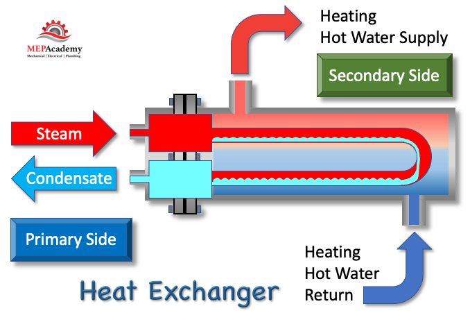
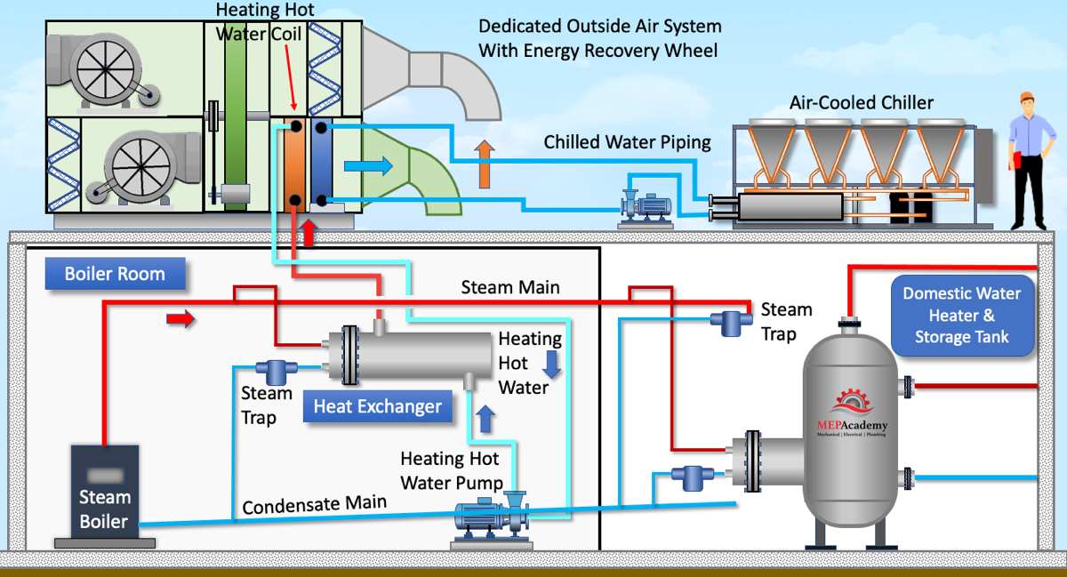
Using steam directly from a steam boiler eliminates the need for additional steam generating equipment. The steam will be delivered from the steam boiler to a manufactured provided direct steam humidifier.
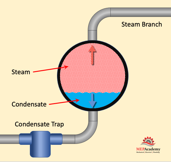
The direct steam humidifier will have the capability to remove dirt and scale particles by straining the incoming steam. There will be a separating of the condensate from the steam, directing the steam condensate to the drain outlet. The steam leaves the humidifier in an all-vapor state where it mixes with the air stream.
Using a direct steam humidifier reducing the need for maintenance as required with other method of humidification as the steam at 212°F (100°C) provides a natural method of steam cleaning the components of the humidifier.
If the facility is existing and already has a steam boiler than this might be the cheapest alternative, depending on where the existing steam pipes are in relationship to where the steam is required.
Steam Distributors
Inserted in the air stream within the supply duct will be the steam distribution tubes that have perforated holes running along its length. The steam exits these holes along the tube, injecting steam into the air stream.
Steam to Steam Humidifiers
Unlike the direct method where steam from a boiler is used directly in the air stream, the steam-to-steam humidifier uses a heat exchanger. This separates the steam generated by the steam boiler from the steam that enters the air stream. This avoids the concern of using treated steam boiler water and the adverse health effects associated with chemicals being brought into the air stream from the boiler.
The steam from the boiler is under pressure, while the secondary steam is often under atmospheric pressure. Having a second source of water increases the concern for impurities in the water and the havoc it can create This increases the need for frequent cleaning.
The time to satisfy a demand for humidification is slower than the direct steam method because the water must be brought to a boil before it can be used.
The indirect steam humidifier provides tight control of output using a modulating control valve, positioning from closed to open based on demand. This allows for a quick response to any space demand for humidification.
If there isn’t a steam boiler at the facility, then there is the option of generating steam with a water source and electricity.
Using electrodes to pass electricity through water is one method, and the other would be to use immersed resistance heating elements to boil water for steam supply. Water quality will be important with the use of electrodes while water quality won’t affect the immersed heating element type humidifier. With both of these types the need to boil water makes it less responsive for quick control.
Gas-Fired Steam Humidifiers
Gas fired steam humidifiers use ionic beds of fibrous mediums that heat the water using gas instead of electricity. The fibrous medium will absorb several pounds of solids in the water and will require replacement when the medium is fully loaded. This leads to reduced time cleaning the tank as the fibrous medium collects a lot of the solids in the water.
Evaporative Humidifiers
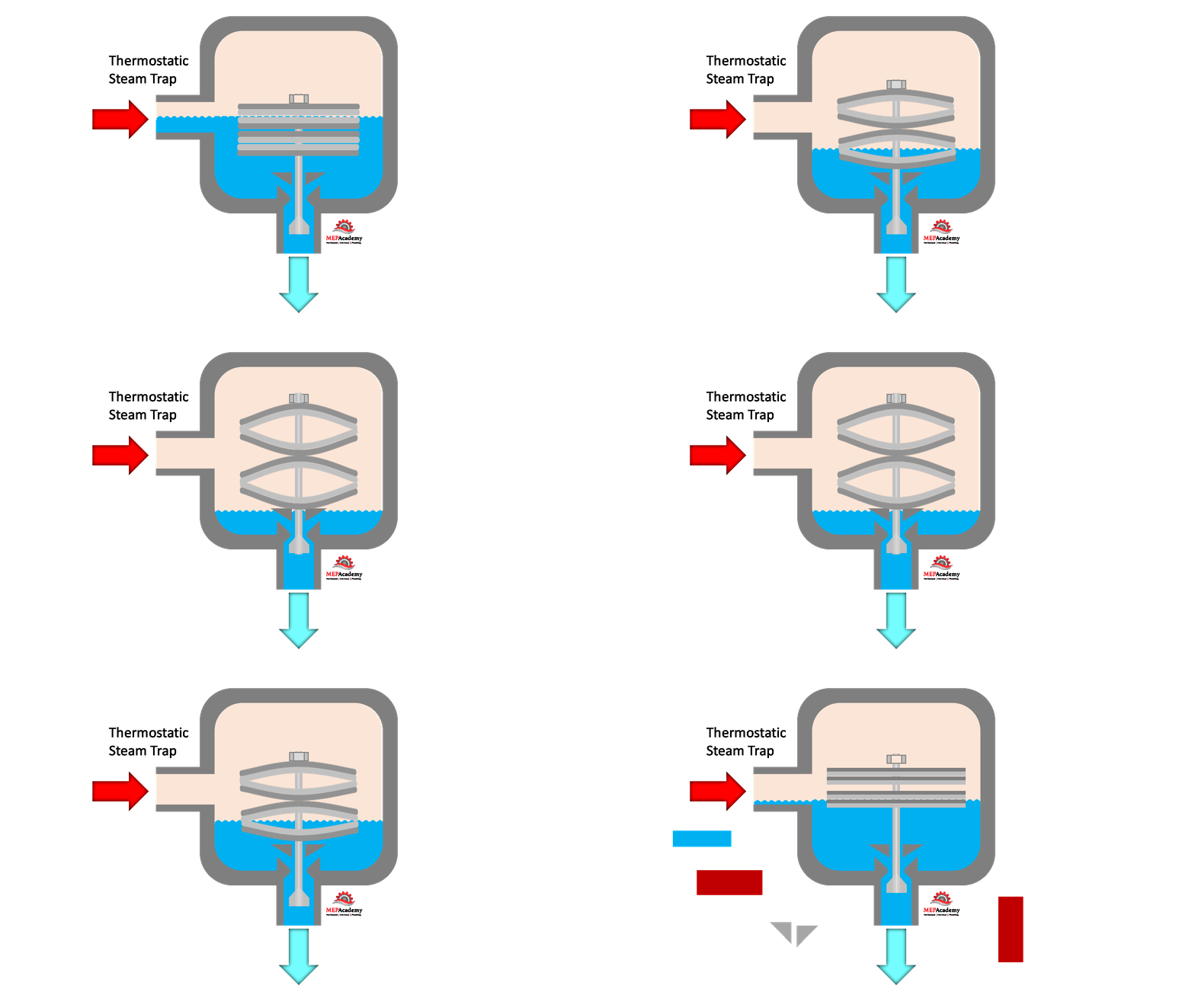
Another option is to use an evaporative humidifier, that can be installed in an air handler or in supply or exhaust ductwork. Air passes over media as water trickles down over it, causing the air to be cooled while increasing its relative humidity.
Moisture is evaporated into the air passing over the wet media, proving an increase in the water content of the air. Sensible heat from the supply air is used for evaporation of the water into vapor, this provides for cooling of the air while also adding moisture. This reduces energy consumption without the need for boilers or gas fired units that burn fossil fuels for the evaporation process.
The HVAC contractor will install the evaporative humidifier in the duct as shown here, then connect the electrical to power the water pumps and controls, then install the water piping to the unit. Its important to provide some form of water filtration to keep the unit from clogging or minerals from depositing on the equipment.
We’ll need a drain line to remove any unevaporated water. Also available is the ability to remotely monitor the system through a BMS system. You can monitor or make changes to the settings; this is typical with most of the humidification systems.
We show this evaporative humidifier installed in the supply ductwork, but they’re also made for installation within the air handler or on the exhaust side with the use of an energy recovery heat exchanger. There are other versions of the evaporative humidification process used for non-ducted applications.
Atomizing humidifiers don’t require a boiler or steam piping as they basically spray water through nozzles to create a mist. That is why they are the most energy efficient type of humidifier. Compressed air and water intersect to create a mist that absorbs heat from the air stream for evaporation into a vapor. This will cause a cooling of the air and will take energy from the air in the form of heat. This would require a larger heating system if using humidification and heating at the same time. If there is insufficient heat in the air stream, then moisture or water could accumulate on the surrounding surfaces of the ductwork, causing damage as water leaks out into the space. Along with direct steam, atomization is quick to respond to a demand for humidification. These systems are best served by deionized water (DI) or reverse osmosis water.
Humidifier Controls
There are several controls that are used for the proper functioning of an humidifier.
High Limit Sensor. This insure that the humidity doesn’t exceed a certain maximum. We’ve set this one for 90% relative humidity as it serves a VAV systems.
Airflow Proving Switch. The humidifier must be shutoff if airflow is not blowing through the duct and over the dispersion tubes. To ensure air is moving over the dispersion tubes an airflow proving switch is proved in the duct downstream of the dispersion tubes. This can be done by using a sail switch, which has a sailboat like sail in the air stream that will rotate on a shaft to make an electrical circuit.
Humidistat. This will control the on and off of the humidifier based on the set point. It works just like a thermostat except that the controlled element is humidity.
Humidifier Controller. Humidifier manufactures provide various levels of controllers with touch screens and LED displays. There are options to have remote monitoring, where you can see what is happening with the humidifier and make changes. It’s possible to have multiple humidifiers connected to one main controller.
Hygroscopic Materials
This is the process whereby materials will absorb water from the atmosphere by absorption or adsorption. Hygroscopic materials like paper are water lovers that absorb water, which can be a problem for a lot of industries. A museum with expensive artwork is sensitive to rapid changes in relative humidity. If the relative humidity is too low than moisture can be pulled or evaporated out of the hygroscopic material such as that which paintings are rendered on. If it can absorb moisture it will be capable of losing moisture content.
Drain Coolers
Many local codes and municipalities don’t allow the draining of 212F (100C) condensate into the sewage system. This will require the use of a drain cooler, which injects domestic cold water to mix with the steam condensate to drop the temperature of the water before it enters the drain.
Steam Boilers
Using direct steam for humidification creates a concern for the air quality when the boiler water is treated with chemicals. These water treatment chemicals can end up in the air, therefore indirect steam to steam is used as a barrier to this issue. Using Indirect steam avoids evaporating the anti-corrosive additives into the air stream, which has been known to cause health problems and the deterioration of paintings and exhibits in museum.
What is Relative Humidity?
The Relative Humidity defines the amount of moisture in the air at the current temperature compared to the amount it could hold at that temperature when 100% saturated. Relative humidity is always expressed as a percentage.
Warmer air can hold more moisture than colder air for the same volume (Cubic Feet) of air. Warmer temperature has a greater capacity for holding water vapor. This chart shows the maximum amount of moisture that can be held in one cubic foot of air at the temperature shown.
At 40F and 100% relative humidity the air can only hold 2.86 grains, but as the temperature increases, say to 70F, the air can now hold 8.06 grains/ft3 of air, and at 100F, the air holds 19.9 grains. So the warmer the air the greater its capacity to hold moisture. Keeping the relative humidity between 40% and 60% for human comfort and safety is the ideal setting.
When relative humidity is at 100%, then the Dew Point Temperature and the Air Temperature are equal. This means that the air is fully saturated with moisture and can’t hold any more moisture. As the dew point temperature rises, the capacity of the air to hold moisture increases.
Relative humidity has been found to be an important factor in the control of airborne infectious diseases, reducing influenza and other viral outbreaks.
As this chart shows, bacteria and viruses love the humidity to be under 40%, or above 60%. This is where they thrive. The same for respiratory infections and Asthma. This is why controlling relative humidity is important.
ASHRAE recommends relative humidity be kept in the range of 30% to 60% for human comfort and health.
Humidification is the process of adding moisture to the air to improve health and comfort, avoid high static conditions and protect processes or products, like museum paintings. Understanding psychometrics, we know that when cold air is heated, the relative humidity drops, and the air feels dry.
What is the best Relative Humidity for my Home or Business?
The level of relative humidity is dependent on what is being served by the HVAC system. This can be artwork in a museum, or paper manufacturing, office workers or a residential home. ASHRAE recommends a relative humidity range of 30% to 60% for comfort. Yale University has done studies that show a relative humidity range between 40% and 60% reduces the viability of viruses. So, for humans somewhere between 30% and 60% is ideal. For materials and sensitive artwork, the values will differ. There are some cases. Like a burn unit in a laboratory where skin cultures are grown that requires a strict 60% relative humidity within a 1% variance.
Calculating the Humidification Load
Calculating the humidification load is to determine how many pounds of water per hour is required to mee the space conditions. There are three things needed before calculating the humidification load for a space. They are as follows;
Space Design Temperature and Relative Humidity required to be maintained.
Volume of air delivered to the space
Outside Air Design conditions for Temperature and Relative Humidity
Isothermal Steam Humidification
Using steam humidifiers has little effect on the dry-bulb temperature of the supply air serving the space. All the energy required to turn the water into a vapor or steam is handled by the steam humidifier. No heat from the air stream is required to turn the water into vapor, so there is little to no effect on the dry-bulb temperature. Steam is complete water vapor at 212°F (100°C). The steam will mix with the air stream, causing the steam to drop in temperature, bringing it close to the dry-bulb temperature of the air.
If we plot this on a psychrometric chart, the dry-bulb temperature would remain unchanged as the humidification process would send a vertical line up the chart in a pure moisture increase.