How do Chilled Beams Work? The use of chilled beams allows for a reduction in the size of Air Handlers and Chillers, as less primary air is served to the space and higher temperatures of chilled water are used for cooling.
Chilled beams are either of the active or passive type, which we’ll explain. The chilled beam will take care of the sensible requirements of the space, while the Dedicated Outside Air System or Air Handler will handle ventilation requirements.
If you prefer to watch the YouTube video of these presentation, the scroll to the bottom or click this link How do Chilled Beams Work
Cool water will circulate through the chilled beams coil and cool the air surrounding it. Cool air is heavier than warmer air, so the effect of the beam cooling the air surrounding it will naturally cause a constant flow or circulation in the space. As the cool air drops the warm air rises, causing the space to cool down. Between the two, the most commonly used one is the Active Chilled Beam.
Active Chilled Beam
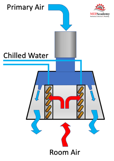
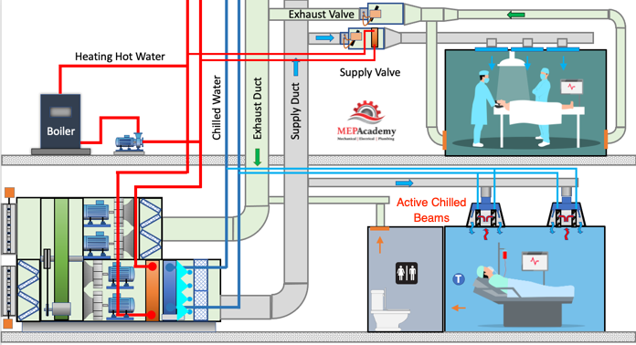
An active chilled beam contains one or two coils in a sheet metal housing, suspended or recessed within the ceiling. Primary air from an air handler or DOAS unit is connected to the chilled beam sending air through nozzles that induce airflow from within the space through the coils. The use of primary air from an AHU allows for greater capacities than the passive chilled beam type. Therefore, Active Chilled Beams are more commonly used. The active chilled beams will have piping and air connections.
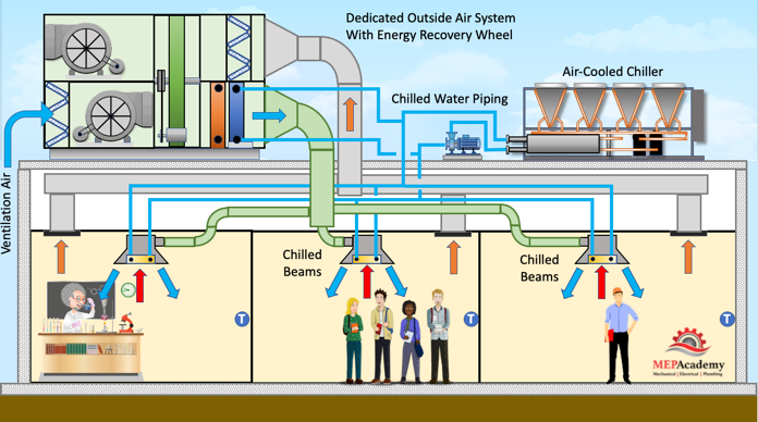
In most jurisdictions Ventilation air is required for all occupied spaces within a building in accordance with ASHRAE 62.1. Using an active chilled beam is when the ventilation air is brought directly to the chilled beam where it creates an induction effect. As the ventilation air blows through jets within the chilled beam housing it causes an induction effect that pulls in room air across the cold coil. This ensures that air circulates within the space in addition to the natural circulating effect caused by the differences in density between cold and warm air.
Since the cooling is being done at the space level and not back at the air handling unit, less ductwork and fan horsepower are required, including a smaller air handler. Chilled water and ventilation air will need to be brought to the space. This could also allow for a reduction in floor-to-floor height as less space is taken up in the attic for large air ducts. More energy can be carried in a small pipe than a large duct, so with the use of chilled water at the zone level, large ductwork can be avoided.
Active chilled beams come in lengths from 2 feet to 10 feet with various output values per manufacture. Outputs range based on width of unit. Common widths include 12” and 24”. Cooling capacity of active beams can range from 600 BTU/FT to 1,100 BTU’s per foot, based on make and model, while passive beams will have lower outputs in the range of 500 BTU/Ft
Passive Chilled Beam
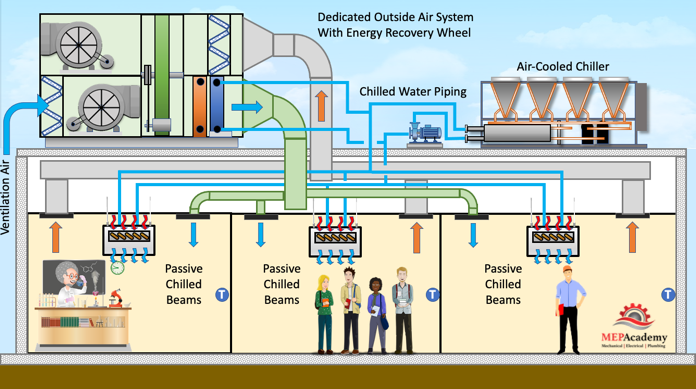
A passive chilled beam contains one or two coils in a sheet metal housing, suspended from the ceiling.
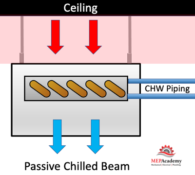
Once again ventilation air is required for the space, except with passive chilled beams the ventilation air is delivered directly to the space, and not through the chilled beam. The passive chilled beam uses natural convection to cause air circulation. This occurs when the cool air surrounding the chilled beams coil becomes denser and drops, while the warmer air naturally rises to the ceiling. This occurs without the use of a fan, hence its passive.
The difference between active and passive chilled beams is how ventilation air is delivered to the space and how much cooling can be achieved with each chilled beam.
Two-Pipe or Four-Pipe Chilled Beams
Chilled beams have the option to have a separate heating and cooling coil, or they can share a coil with the proper control valve arrangement. A four-pipe system uses two separate coils which gets you four pipes, two chilled water and two hot water pipes. Obviously the four-pipe chilled beam will be heavier as there are two separate coils.
Air Stratification
Air stratification is when you have different levels of air temperatures. With chilled beams this involves the natural stratification of warm air versus cold air. Warm air will rise while cold air being denser will drop to the bottom.
DOAS or Central Air Handling Unit
The chilled beams are designed to handle sensile load while leaving ventilation and latent load requirements to the main DOAS or AHU. This eliminates the need for condensate drain piping at each chilled beam, as the temperature will be maintained above the dewpoint temperature. The AHU unit can be sized just to handle the ventilation requirements, thereby allowing for a smaller than normal unit.
It’s imperative that the AHU be sized to handle the dehumidification requirements as the chilled beams are designed to handle strictly sensible cooling. The primary air must be dry enough to handle any space latent load while maintaining the indoor dew point at a low enough level to prevent condensation from occurring on the chilled beam coil. If the level of humidity is not properly provided for by the AHU, then condensation can occur on the chilled beams and water could drip on the space below.
Chilled Water Supply Temperature & Humidity Levels
The chilled water temperature to a chilled beam is in the range of 55°F to 62°F (12.7°C to 16.6°C) which is higher than a traditional chilled water system of 42°F to 45°F (5.5°C to 7°C) to avoid condensation. To avoid condensation the chilled water temperature needs to be maintained above the rooms dew point temperature, the point at which condensate occurs. The dewpoint transmitter will assist in maintaining the chilled water supply temperature to the chilled beams at 3°F to 4°F (1.6°C to 2.2°C) above the room dewpoint temperature.
The temperature difference between the supply and return chilled water will be low, in the range of 5°F to 6°F (2.8°C to 3.3°C), making the return water temperature range from 60°F to 67°F (15.5°C to 19.4°C). The smaller delta-t requires a greater flow when compared to a typical VAV chilled water coil under ASHRAE 90.1 which requires a 15°F (8.3°C)temperature difference between the supply and return, with a minimum of 57°F (13.8°C) leaving water temperature. Chilled beams are excluded from the mandatory delta-t requirements of ASHRAE 90.1 as an exception 6.5.4.7 #6 states that “Coils with design entering chilled-water temperatures of 50°F (10°C) and higher” are exempt.
In order to achieve a larger capacity chilled beam, you need either greater water flow or a higher delta-t, as the equation is Q = GPM x 500 x Delta-T. By increasing flow or the delta-t you can increase the capacity. But chilled beams are limited by their size and the temperature at which the chilled water can be delivered to avoid condensation.
With an increase in the chilled water supply temperature there will be an increase in the duration for which a waterside economizer could be used.
VAV System vs Chilled Beam
The best way to see some of the benefits of a chilled beam system is to compare it to the typical VAV system. All occupied spaces require some form of ventilation air per ASHRAE 62.1, but the method of using reheat in a VAV system to control space temperature is less efficient.
Capacity control for space temperature is handled differently between the two systems. The VAV system will reheat the air that has already been cooled to maintain space temperature requirements. The chilled beam system will modulate the water flow to the coil to respond to load demand, but without the wasted energy of reheating. Chilled beams use a constant volume of air, while a VAV system varies the quantity of air to the space.
Instead of the delivering cold air through large ducts, the chilled beam system uses the more energy efficient carrying capacity of piping. Chilled water piping carries over 3,500 times the volumetric heat capacity than that of air ducts. This saves on ceiling space and allows for lower floor to floor heights or higher ceilings. The VAV system increases the volume of air to satisfy the space, while the chilled beam system increases the flow of chilled water.
The ventilation air delivered to the space using the chilled beam system is the proper amount based on space usage and occupancy level. With a VAV system the volume of ventilation air is less precise as the ventilation air is mixed with return air before being delivered to the space.
Dewpoint Transmitters and Moisture Sensors
Dewpoint transmitters are used to sense space dewpoint levels to avoid condensation in the rooms where chilled beams are installed. Since chilled beams are designed to avoid condensation and are installed without condensate drain piping, the avoidance of condensation is important.
Moisture sensors can be strapped to the chilled water piping to indicate if there is the presence of moisture. This would allow a signal to be sent to the control valve to stop the flow of chilled water to the chilled beam. This is a precautionary measure if deemed necessary.
Benefits of using Active Chilled Beams
- Reduced size of main supply ducts.
- Reduced size of Air Handler and/or Central Fans
- Elimination of reheat coils at each zone
- Reduced size of Heating Hot Water System
- Reduced Chiller Size
- Reduction in energy use
- Increased time of use for waterside economizers
- Quieter than conventional systems
- Reduction in floor-to-floor heights
- Reduction in mechanical room size
It’s possible that a high performance VAV system will beat the energy savings of an Active Chilled Beam system. Use energy modeling software to check if the building that you’re proposing for chilled beams is as energy efficient as a high performance VAV system.
Installed Cost of a Chilled Beam
The installed cost of a chilled beam system could also be higher than a conventional VAV system due the requirement to route chilled water piping to each space in lieu of just to the air handler room. Also, chilled beams have low capacities due to the higher chilled water temperature and may require lots of them to achieve the load demand of the space. The smaller Delta-T will require more flow to meet the demand if we look back at our formula Q = GPM x 500 x Delta-T, if the delta-t is lower than the GPM must be higher to achieve the same capacity. More capacity can also be added by adding more coil area, which adds more cost.