Portable air conditioners (PACs) offer a convenient way to cool spaces without permanent installation. Whether you’re renting, need a spot-cooling solution, or simply prefer mobility, a portable AC might be a smart option. This guide breaks down the key factors to consider before buying.
Types of Portable Air Conditioners
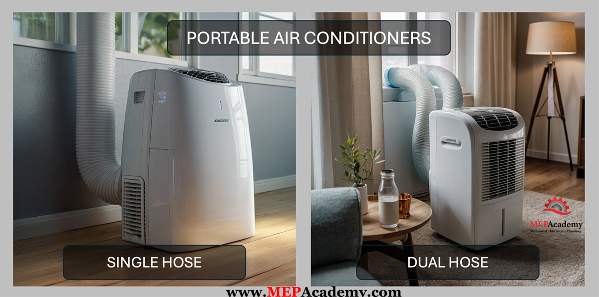
- Single-Hose Units – These draw warm air from the room, cool it, and expel hot air through a single exhaust hose. They’re usually more affordable but less efficient.
- Dual-Hose Units – These use one hose to draw in outside air and another to expel hot air. This design increases efficiency and is better for larger rooms. You may only see one hose with some models as they hide one hose inside a larger hose.
- Evaporative Coolers (Swamp Coolers) – Technically not ACs, these use water to cool air and work best in dry climates. They don’t require venting but don’t reduce humidity.
Cooling Capacity Options and Meaning
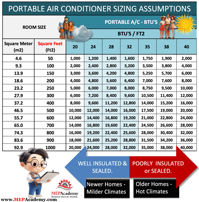
Cooling capacity is measured in BTUs (British Thermal Units). The higher the BTU, the more space it can cool. Air conditioners are sized based primarily on outside air conditions that would occur at the peak of the cooling season such as in July or August, depending on where you live. Most of the time the air conditioner will run at partial load. Over sizing an air conditioner is not a good idea, see why in our video “Should you Oversize your Air Conditioner?”
- 8,000–10,000 BTU: Good for small rooms (up to 300 sq ft)
- 12,000–14,000 BTU: Medium rooms (300–500 sq ft)
- Over 14,000 BTU: Large rooms or open spaces
It’s important to choose the right size for your space, as an undersized unit won’t cool effectively, while an oversized one may cool too quickly without removing excess moisture. For a video that explains what a BTU is check out our Video.
There are a lot of factors that go into the proper sizing of an air conditioner that is beyond the scope of this buyers guide, but since were only dealing with a Portable Air Conditioner we can make some assumptions and bypass the rigor of a complete heating and cooling load. If you want to know more about the heat transfer process see our video explaining the various methods on Heat Gain. Basically the cooling load is based on heat gain through walls, floors, ceilings, doors, windows, skylights, and by infiltration, ventilation, plug loads and occupants.
Note: New DOE standards (2017 and newer) may show “ASHRAE BTUs” and “DOE SACC BTUs.” SACC is more accurate and usually lower due to real-world testing conditions.
CEER: Combined Energy Efficiency Ratings
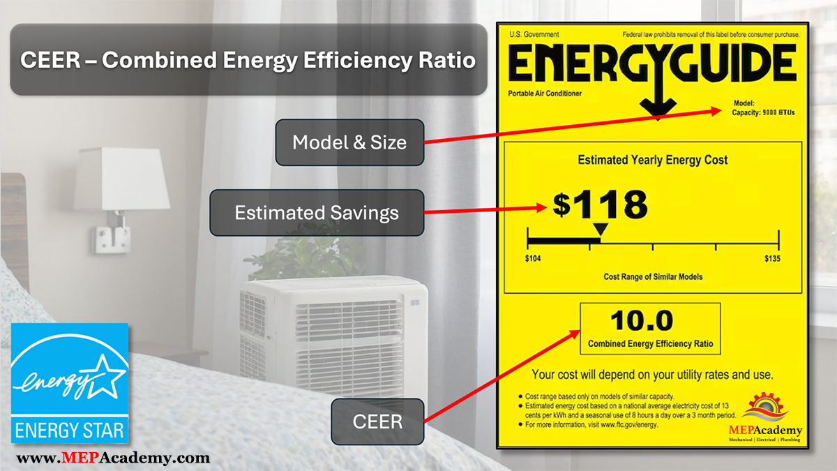
CEER measures how efficiently a room air conditioner uses electricity, including both when it’s actively cooling and when it’s on standby. It gives a better overall picture of real-world energy use.
It’s expressed in: BTUs per watt-hour (BTU/Wh)
How Is CEER Calculated?
CEER=Cooling output (BTU/hr) / Active power (Watts) + Standby power (Watts)
Where:
- Cooling Output (BTU/hr) is how much heat the unit can remove from the air per hour.
- Active Power is power consumed while the unit is running.
- Standby Power is power consumed when it’s plugged in but not actively cooling.
So it’s: Cooling performance divided by total power consumption, including when idle.
What Does a CEER of 9 Mean?
If a room air conditioner has a CEER of 9.0, it means: For every 1 watt-hour of electricity used (active + standby), the unit provides 9 BTUs of cooling.
📈 Efficiency Perspective:
| CEER Rating | Efficiency Level |
|---|---|
| < 8.0 | Low |
| 8.0 – 9.9 | Moderate to Good |
| 10.0+ | High (ENERGY STAR-level) |
| 12.0+ | Very High Efficiency |
ENERGY STAR-qualified room ACs typically have a CEER of 10 or above, though this can vary by size.
🧾 Real-world Meaning:
If you’re comparing models, even a 1-point increase in CEER can mean significant long-term savings. Some models, like the Midea Duo, boast high Combined Energy Efficiency Ratio (CEER) ratings of 10.8
A CEER of 9 is decent, especially for smaller or older units. Keep in mind that window air conditioners can have a CEER of 16 or greater. There are some sacrifices to using portable AC units.
The higher the CEER, the lower your electricity bills and better performance.
Noise Levels
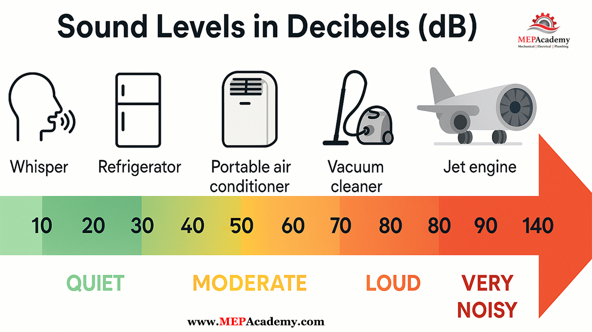
Noise levels are typically measured in decibels, with lower numbers indicating quieter operation. Most portable ACs range between 50–60 decibels, similar to a normal conversation. Dual-hose and higher-end models tend to be quieter. Look for decibel ratings (dB) if you’re noise-sensitive or plan to use it in a bedroom.
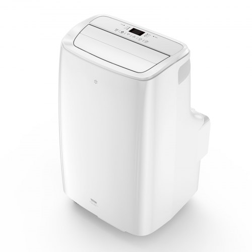
Physical Size
Portable ACs come in various sizes and weights. Consider units with handles and wheels for easier movement. Lighter models are better for frequent relocation, while heavier units may offer more powerful cooling. Portable ACs vary in size but typically range from 25–35 inches high and 12–18 inches wide. Weight ranges from 45–90 lbs, so consider models with sturdy casters and handles for easy movement.
Proper Placement and Venting Requirements
All compressor-based PACs require venting hot air outdoors, usually through a window. Most come with window kits for easy installation. Place the unit near a window and power outlet, ensuring the exhaust hose is properly connected. Avoid placing units in tight corners or near obstructions—allow airflow around the unit for optimal performance.
Condensate Drain Options
As PACs remove humidity, they collect moisture. Drainage methods include:
- Self-Evaporating: Most common. Evaporates most or all moisture through the exhaust hose.
- Gravity Drain: Requires connecting a hose to drain water continuously.
- Internal Bucket: Water collects in a tank that needs manual emptying.
Choose based on your room’s humidity levels and how hands-on you want to be.
Are They Worth the Cost?
Portable ACs are ideal for renters, small spaces, or temporary cooling. While less efficient than split or window units, they provide flexibility. They’re especially worth it when central AC isn’t an option or when you want to cool just one room. While portable ACs can be energy-efficient and save on monthly electric bills, their effectiveness depends on proper sizing and usage. They’re particularly useful for spot cooling or in situations where window units aren’t feasible.
Electrical Power Requirements
Most PACs run on standard 115V outlets, but models over 14,000 BTUs may require dedicated 20-amp circuits. Some high-powered units may need a 220V outlet. Always check the manufacturer’s specifications for power requirements. Check your breaker panel and room outlet capacity before purchase to avoid tripping circuits.
Heating Options
Many modern units offer heat pump functions for year-round use. These models can both cool and heat, reducing the need for separate appliances. Look for “4-in-1” models offering cooling, heating, dehumidifying, and fan modes.
Maintenance Requirements
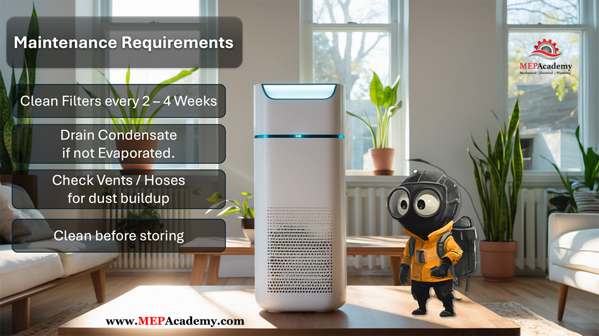
- Clean or replace filters regularly (every 2–4 weeks in summer).
- Drain condensate tanks or check hoses if not self-evaporating.
- Inspect and clean vents and hoses to prevent dust buildup.
- Seasonal storage: Clean thoroughly before storing during winter.
Warranty Available and What to Look For in Coverage
Most manufacturers offer a 1-year limited warranty on parts and labor, with 5-year warranties on sealed systems (compressor, evaporator, condenser). Warranty coverage varies by manufacturer. Look for warranties that cover both parts and labor for at least one year. Some premium models may offer longer coverage periods. Look for:
- In-home service or carry-in options
- Compressor coverage beyond 1 year
- Read the fine print: Some only cover parts, not labor or shipping
Price Range to Be Expected
Portable air conditioners range in price from budget models around $300 to premium units costing $700 or more. Factors affecting price include cooling capacity, features, and energy efficiency.
- Budget Models (8,000–10,000 BTUs): $250–$400
- Mid-Range Units (12,000–14,000 BTUs): $400–$600
- Premium Models (dual-hose, with heat, Wi-Fi): $600–$800+
- Commercial/High-Capacity Units: $900–$1,500+
Features like smart connectivity, quiet operation, and multi-functionality raise the price.
Conclusion
In conclusion, when choosing a portable air conditioner, consider your specific needs, room size, and budget. Proper sizing, energy efficiency, and features like noise level and drainage options are crucial factors in making the right choice for your cooling needs. Portable air conditioners can be a smart, flexible solution for targeted cooling and heating. Understanding the types, features, and maintenance requirements helps ensure you get the best value for your needs. Evaluate your space, power setup, and comfort priorities before buying—and enjoy the breeze.
Frequently Asked Questions (FAQ)
Yes, portable air conditioners can effectively cool individual rooms when properly sized and vented. They’re ideal for bedrooms, offices, apartments, or areas without central AC.
Look at the BTU rating. For example:
8,000–10,000 BTU: Small rooms (up to 300 sq ft) 26 to 33 BTU/Ft2
12,000–14,000 BTU: Medium rooms (300–500 sq ft) 24 to 28 BTU/Ft2
Over 14,000 BTU: Large rooms or open layouts
Also consider room factors like sun exposure, ceiling height, and number of occupants.
Yes, all compressor-based models must vent hot air outside, usually through a window. If not vented, they’ll just circulate warm air, reducing cooling efficiency.
Single-hose: Easier to set up but less efficient, as it pulls air from the room.
Dual-hose: More efficient; one hose brings in outside air, the other expels hot air. Best for larger rooms and longer cooling cycles.
Yes, they dehumidify while cooling. Some units have a separate “dehumidify” mode. Units typically collect or evaporate moisture as they operate
Most newer units are self-evaporating and rarely need draining. Others have:
A drain plug for gravity drainage
A bucket or tank that must be emptied manually
An option to connect a drain hose for continuous draining
They make some noise—typically 50–60 decibels, like a fan or quiet conversation. Some premium models are quieter, making them suitable for bedrooms or offices.
Not easily. They need an exhaust path to remove hot air, usually through a window. If there’s no window, you’d need to vent through a wall, drop ceiling, or sliding door.
They use more power than fans but less than central AC. Energy-efficient units (EER 10 or higher) are more cost-effective. A 10,000 BTU unit typically draws 900–1,200 watts.
Some units include a heat pump mode and can provide heating during colder months. These are labeled as 4-in-1 or AC/Heater Combo models.
Clean filters every 2–4 weeks
Drain water if not self-evaporating
Check vents/hoses for dust buildup
Clean before storage to prevent mold or mildew
With proper care, they typically last 5 to 10 years. Regular maintenance and storing them properly off-season can extend their lifespan.
Yes, if you need flexible cooling without permanent installation. They’re perfect for renters, spot-cooling, or rooms where central AC isn’t effective.