A labor database contains units of labor for each task that is required for a particular project. If you are installing sheet metal then you need to know how long it takes to install the air distribution ductwork based on its size or weight in addition to taking into consideration the working conditions of the project site. It takes more time to install a 60” x 36” duct than a 12” x 12” duct.
But how much time does it really take to install either of these ducts? This is where a labor database comes into the picture, as the basis for which you will make adjustments to.
If the company you are working for doesn’t have their own labor database, then there are third-party labor databases available.
With the onset of the digital age there are many companies offering their computerized estimating software that contains a labor database, estimating software companies such as Trimble, QuoteSoft, and FastDuct. These companies integrate the labor database of the industry leaders in sheet metal standards, SMACNA (Sheet Metal and Air Conditioning Contractors National Association).
SMACNA
The SMACNA labor database provides units of labor for the fabrication and installation of ductwork and accessories in addition to miscellaneous pieces of HVAC (Heating Ventilating & Air Conditioning) equipment. In addition, SMACNA provides education and advocates for various legislation on Capitol Hill. SMACNA labor data is the most widely used labor database for computerized estimating software programs.
SMACNA labor provides you with several options on how to report out your labor, for instance you can choose to see labor productivity in Lbs/Hr or Hours/Piece.
RS Means (Gordian)
RS Means which was purchased by the Gordian Group also has a labor database but you won’t find it used in any of the top HVAC estimating software programs. They publish various books and have an online version of their database which contains over 77, 622 line item units. The RS Means database contains material and labor, not just labor like the SMACNA database. They offer several levels of access to their database, including unit price cost, cost for assemblies, square foot model cost, Union and Open Shop data sets, Life cycle cost estimating in addition to their eBooks and published cost data books.
Material Databases
Maintaining material cost data for construction elements is a daunting task unless you have a supplier that provides you with the information on a timely basis. Prices change over time do to economic conditions such as inflation and the overall competition amongst suppliers.
To make sure you are bidding projects with the latest prices in your database you will need to have a system in place to update the prices. This can either be done manually by calling your supplier every several months to get the latest price or submitting a bill of material for each project your bidding on.
HVAC Piping and Plumbing Material Databases
If your company is using an estimating software program this becomes a lot easier on the HVAC Piping and Plumbing side, but still requires you to periodically check with your suppliers for price changes or changes to their discount multiplier. A discount multiplier informs you how much you can deduct from the manufactures published retail pricing.
If you are taking off HVAC piping or Plumbing this is automated by several companies that sell material price databases that contain tens of thousands of prices on pipe, valves and fittings. These prices are automatically downloaded from the internet into your estimating software and the only thing you need to do is maintain your discount multiplier for the different manufactures.
For those companies large enough to have a purchasing department or an individual responsible for making purchase, the process of getting updated pricing can be handled through them. They will be in constant contact with your local suppliers and will notify you when prices change.
Sheet Metal Material Database
You will most likely be using a local fabricator for your rectangular and round duct and fittings. There are sheet metal fabrication companies that sell to the local contractors. There are some HVAC sheet metal contractors that have their own shop fabrication equipment and thereby fabricate their own ductwork.
Their fabrication shop can vary on the type and amount of shop fabrication equipment they own, which will dictate the type of ductwork they can make. Shop fabrication equipment is expensive and so is the labor to keep the shop running. Having your own fabrication shop allows you to control the quality and timely delivery of ductwork and fittings.
Maintaining a set of estimating standards will create a more efficient estimating department or disciplined estimator. By creating estimating standards you will be able to quickly identify systems from one drawing to the next, and be able to assemble your estimates in the same manner from one project to the next. Estimating standards make reviewing and bidding projects more efficient by having a structured protocol for each step of the way.
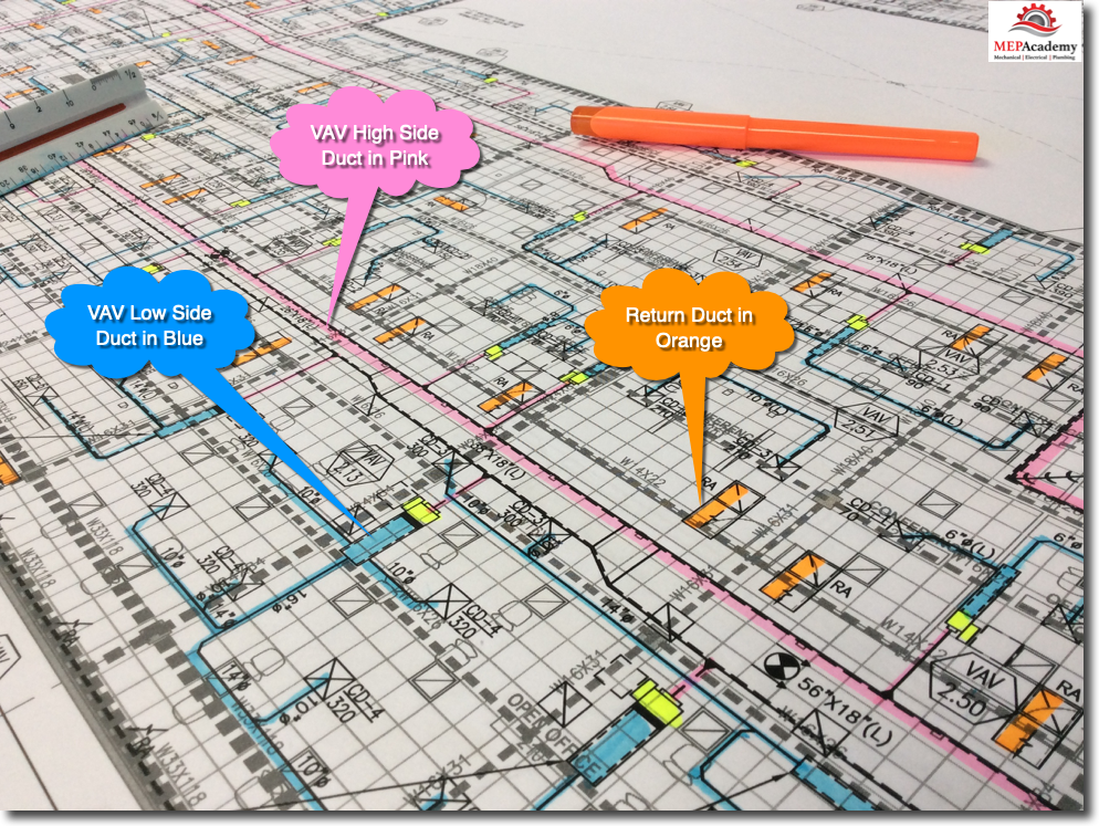
When starting a takeoff you must have a way to record what has been taken off and what has yet to be done. This is best done by coloring the portion of the ductwork that has been takeoff. If you’re using an estimating software program, then the coloring or indication of what has been taken off will be automatically done for you. All you have to do is setup the colors per system type, such as VAV High Side, VAV Low Side, Supply, Return and Exhaust air systems.
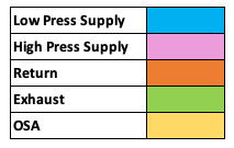
It’s also important to color each system a different color, as this will help you quickly identify a system by its equivalent color code. For example; Low Pressure Supply Air would always be colored light blue, while return air would be colored orange. By following this simple rule of coloring from one drawing to the next, it will make it easy to view drawings using a visual representation of system types.
Sheet Metal Takeoff Colors Chart
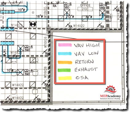
These are the standard colors we will be using through-out this training. It is also helpful for those that may not be familiar with your color coding, to put a legend on the drawing as shown in the picture below.
Color Chart Legend
It’s important to color your takeoff as you record the material taken-off, this will ensure that you can quickly recognize where you last left off. It’s also important that you don’t color in any of the material that you haven’t taken off into your takeoff sheet or computer.
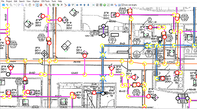
Trimble AutoBid Onscreen Takeoff System Colors
Computer estimating programs also use different colors to represent different portions and system types in a material take-off. Shown above is the Trimble AutoBid Sheet Metal Onscreen Takeoff View with different colors shown for the different system types.
Your company should establish a standard that everyone uses in order to maintain consistency. After a while you can instantly recognize a system based on the colors that were used during takeoff as we’ll show you below.
High Pressure Supply Ducts
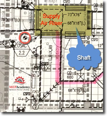
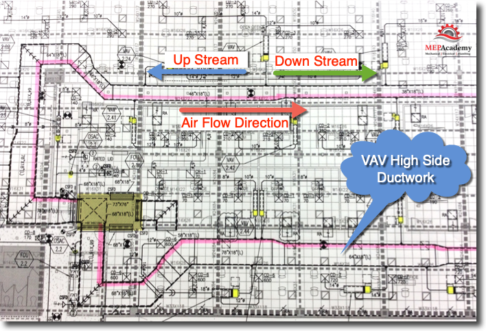
Begin your takeoff at the source of the air, which is often a main duct coming out of a shaft as shown below for this VAV high-side supply duct in a commercial HVAC system. It’s not actually seeing high static pressure, but the nomenclature is used to distinguish the low side from the high-side of the VAV terminal box. The specifications will define the static pressure to be used at various location in the duct system.
The first item at the shaft wall is a tap then a CSFD (Combination Smoke & Fire Damper). Remember that shafts can carry air from one floor to another and will usually require some form of smoke and or fire damper to protect the migration of smoke from one floor to another through the ductwork.
The duct will act as a transportation highway bringing toxic smoke that may occur from a fire on another floor through the shaft, so it is important to be aware of the requirements for smoke and fire dampers. We also know that a Smoke or Fire Damper will need an access door in the duct and another in the ceiling if the ceiling is constructed of inaccessible material like gypsum board.
VAV Highside Coloring
In this example we will take off all of the High-side VAV Supply main duct and color it pink to indicate the high pressure side. Of course, most likely it’s not high pressure ductwork, but can be anything from +2” sp to + 6” sp. We use this terminology only to distinguish the upstream from the downstream side of the VAV box.
As you can see in the drawing it’s easy to now identify where the high-side supply air duct main runs through-out the building.
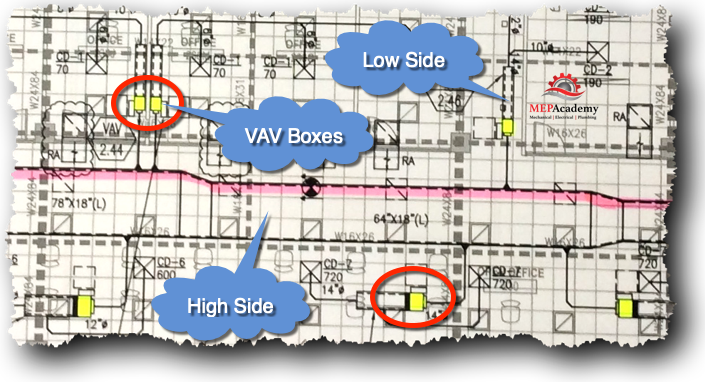
When we have finished with the High-side main duct we will color all of the VAV Terminal Units or VAV Boxes with a yellow highlighter. You could also do this in the beginning, while counting how many VAV boxes there are.
This will help us quickly visualize the demarcation between high-side and low-side. The VAV box separates the two pressure classes as often defined by Engineers and the static pressure requirements as seen by the duct.
VAV High Side Example
Low Pressure Supply Duct
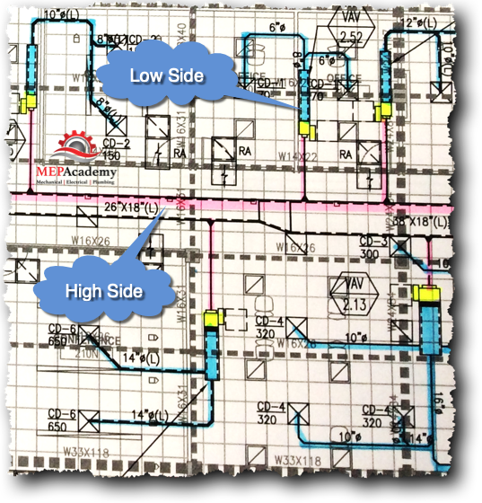
After completing the high pressure side takeoff then you can start with the low pressure side of the VAV box. We will use blue as our color for the low pressure side. This will allow you to quickly see where the high and low side start and stop.
Low Pressure Supply Example
Return Air Ducts
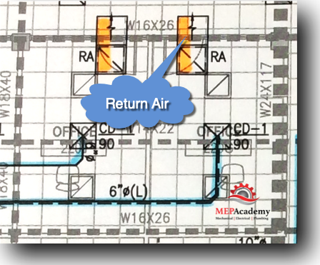
After completing the high and low pressure duct takeoff then proceed to the return air system. In this example the return air is not ducted back to the air handler, it is returned through the attic space un-ducted.
What the engineer has shown is sound boots in each office or space so that noise is not transmitted from one office to another through the return air grilles. In this case it appears that each office space has full height walls that would trap any return air, so a means for getting out of the space is required.
Return Air Systems
Additional Fittings
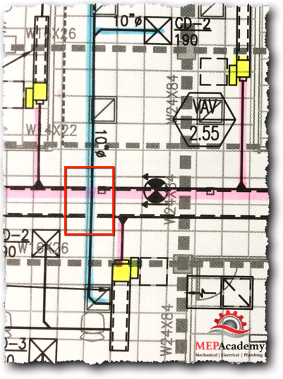
Another thing to consider is that engineers are not detailing the design drawings and additional fittings will be needed as the drawings are considered diagrammatic. This means that you will need to make some judgment as to where additional fittings will be required as shown in the below picture.
Outlined in the red box in the picture below you can see that the VAV box is at a similar elevation as the main duct. The VAV box is shown in yellow and the main duct has been colored pink. The low pressure duct in blue starts from the plenum of the VAV box and turns and goes back over the main duct without any fittings shown.
Extra Fittings Example
It would be impossible to do this if the VAV box and main duct are at the same elevation because that would mean that the low pressure duct is also at the same elevation.
In this case its best to add at least four (4) additional fittings, either 90 degree or 45 degree elbows. This will get you up and over the main duct and then back down over the other side of the main and back down to the starting elevation. If you are changing elevation of the low pressure duct then you can use just two (2) fittings to get you up over the main duct and then remain at that elevation without dipping down back to the starting elevation.
Overall View
It should now be easy to spot anything that was missed. You will notice any white areas of the drawing that haven’t been colored that may contain a piece of duct.
Estimating Drawing Standards
Sheet Metal Material Takeoff Sheets
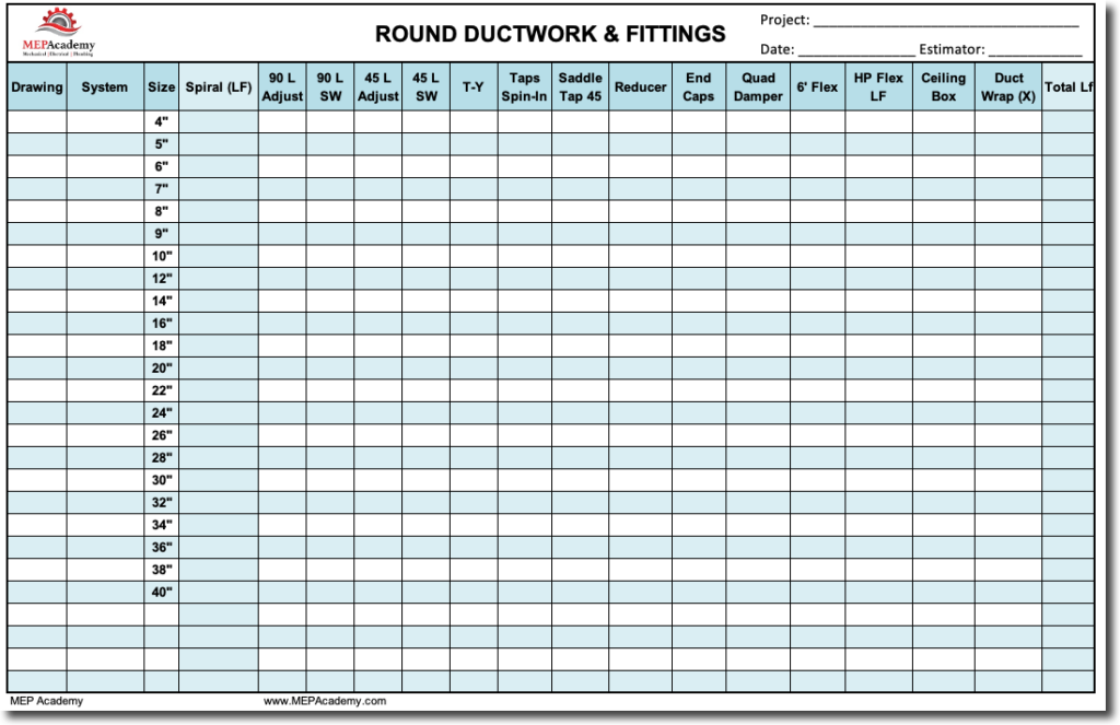
Round Duct Takeoff Sheet
When doing manual takeoffs without the benefit of a computer program, you should use preprinted forms or a computer spreadsheet to tally your material takeoff.
Round Duct Takeoff Sheet
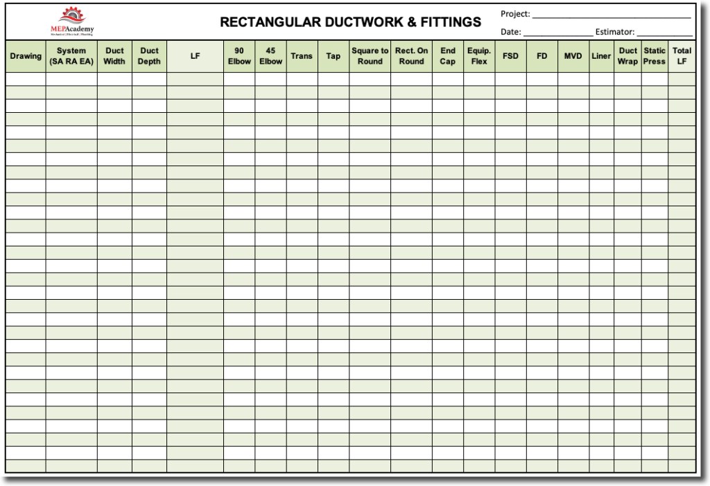
Rectangular Sheet Metal Takeoff Sheet
The most common fittings are shown on the takeoff sheet. You can rename any of the fittings that you commonly use in your area. The idea is to make takeoff’s as easy as possible without duplicating efforts.
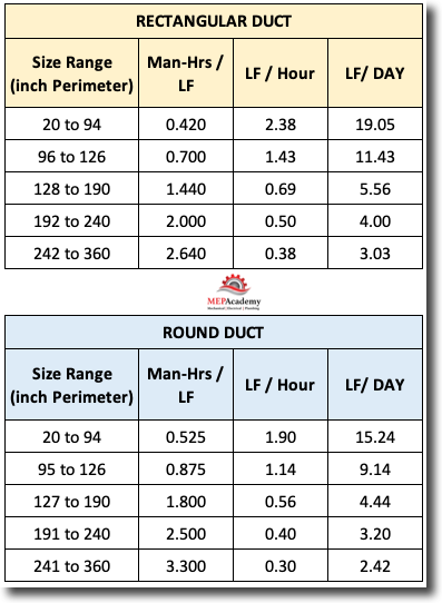
A sheet metal takeoff needs to be properly broken down so as to allow for easy labor analysis when you are complete. To do this, you will need to separate ductwork according size ranges that use similar productivity factors, such as is shown in this replication of the Military’s productivity schedule.
Military Sheet Metal Productivity-Chart
As can be seen in the chart above, the sizes are broken down into ranges based on the full perimeter of the ductwork. The perimeter is the same as the stretch-out we discussed in a previous section. If you have a 24” x 12” section of ductwork, then the perimeter (stretch-out) would be as follows;
24” + 12” + 24” + 12” = 72”
This would fall on the first line of the chart for rectangular ductwork.
The chart separates rectangular duct into different size ranges. All rectangular ductwork that ranges in size from 20” to 94” in total perimeter, equals 2.38 Linear Feet per Hour or 19.05 Linear Feet per Day. This would equal any ductwork where the perimeter or stretch-out length fell within those values, such as; 22” x 24” ductwork, which when stretched out equals a 92” perimeter (22” + 24” + 22” + 24” = 92”)
Zone, System & Size Breakdown
When doing a sheet metal takeoff, it’s helpful to separate the takeoff according to the following;
Drawing # (M-1, M-2)
Zone (AHU-1, or AC-5) Air Handling Unit #1 or Air Conditioner #5
System (Supply, Return, Exhaust, Relief, etc.)
Material Type
Size Ranges
By breaking out your takeoff in a structured way like this, it makes it easy for labor analysis and addendum modifications. Your takeoff might be organized as follows;
M-1, AC-5, Supply Air.
M-1, AC-5, Return Air
M-1, AC-5. Outside Air
If a week later an addendum was issued that changed the ductwork on AC-5, this would be an easy change for you since you have isolated it within your takeoff.
Starting the Takeoff
It’s best to start at the source of the air being provided into the duct. This could include an Air Handler, Air Conditioner, Fan or just the most upstream section of the ductwork, where it is at its largest dimension and CFM capacity.
Estimating Review Meeting
Depending on the size of your company there will be varying amounts of individuals participating in the estimate review. For a small company this could fall squarely on the owner or the estimator. For larger companies, the estimate review meeting could include field supervisors, estimating managers, salespeople and other decisions makers. The larger the project, the larger the potential estimate reviewers involved.
For this estimating review meeting, be sure to have copies of the labor reports for all those who will be attending, along with a copy of the sheet metal specialties sheet. Be organized and professional at all times, this is where you establish your credibility as an estimator, by the way in which you present yourself and your estimate.
Estimating Sign-Off Threshold Amounts
Some companies will establish threshold for sign-offs of the estimate based on the dollar amount of the bid. For project greater than a million dollars, maybe your estimating standards would require that the bid be reviewed and signed by an executive of the company. The more difficult the project, the more you want to get an experienced opinion of others.
Example of Threshold Sign-off Authority
Estimator $0 to $250,000
Estimating Manager $0 to $500,000
Vice President $0 to $2,000,000
Owner. President $0 to Infinity
Project Kickoff Meetings
When a project is successfully won and the project documents have been handed over to the construction department, there should be some form of project kickoff meeting. During this meeting the estimating team or individual estimator would explain the approach to the estimate and the values of the estimate.
At this point in the process, the estimator is usually the one most intimate with the project scope and details, so is one of the best to communicate all the information about the project. The project kickoff meeting will ensure that key information is transferred to the team that will be responsible for building the project.
Project Closeout Meetings
It’s also good to have some form of project closeout meeting, or lessons learned feedback so that anything of significance learned while executing the construction of the project can be shared with the estimators or estimating department to make them more efficient in future estimates.
Acknowledging where the estimate went over or under the estimated amount will help to make future adjustment in labor or material values as required to bring each category of the estimate in alignment with the actual cost. Realizing that labor is always going to be the biggest variable, this is an area for continuous study to better understand how your company performs in various environments and conditions.
Quality Control
Double checking your calculations and having a second set of eyes review the bid and proposal will help eliminate possible errors. Your company should have some measure of ensuring the accuracy of your bids. This can be by using estimating software, bid review meetings or several people reviewing the bid and proposal for projects exceeding a certain dollar value.
Summary
Establish estimating standards for your company so that as you grow there will be a way to have all your estimates uniformly arranged. This will make it easier and quicker to review and audit estimates.
Estimating standards will provide consistency from one estimate to the next. This includes using one estimating spreadsheet that gets updated as things change, but which mostly remains consistent from one estimate to another.
The front end documentation is not contained within the CSI (Construction Specification Institute, Inc) MASTERFORMAT divisions (Division 22 – Plumbing, Division 23- HVAC, Division 26 – Electrical). We consider front-end documentation to be all the sections and information setout before division 1 of the specifications, including the RFP (request for Proposal), Instructions to Bidders, Supplemental Instructions to Bidders, or an Invitation to Bid.
This is the first place to begin an estimate. We will cover some of the information found in these sections, the RFP and Division 1 (General Requirements).
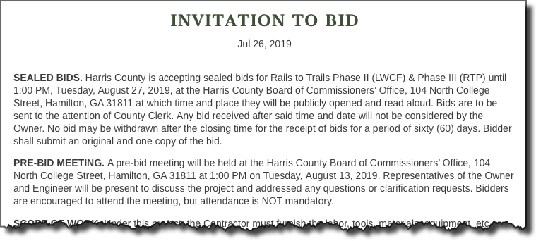
The invitation to bid will provide you with most of the information you will need to make a decision on whether to bid the project and the timelines of the proposal.
Invitation to bid
Bid Date and Time
Make sure to post the date and time of the bid, along with the RFI deadline and any job walks on your Bid Log and Bid Schedule.
As can be seen in the above example Harris County is accepting bids until 1:00 pm, Tuesday, August 27, 2019 at the Harris County Board of Commissioners Office for a certain project. This is a public project and the bid date and time are usually strictly enforced. If you are a minute late, your bid will be rejected.
Pre-Bid Meeting or Job Walk
Is there a job walk scheduled for this project? Is the walk mandatory? Is this a renovation project?
If the job walk isn’t mandatory, you could show the owner or general contractor that you’re interested in the project by attending the job walk or any pre-bid meetings. Make sure to review the drawings and specifications before the pre-bid meeting.
If this is a renovation project, then the pre-bid job walk would be a great time to determine the existing conditions under which you will be required to work during construction.
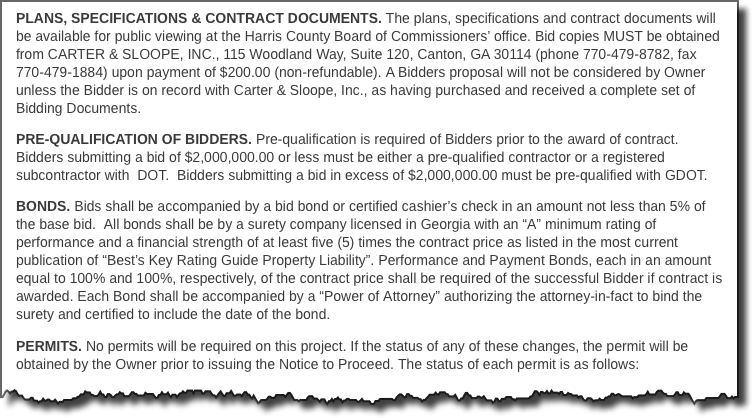
Plans and Specifications
Plans and specifications are often purchased through a depository or printing company that holds the documents for a public or private entity. In the below example you would need to pay $200 for a copy of the documents which is mandatory to be considered for the submission of a bid. With concern for the environment and the cost of printing documents, many entities have moved to delivering their plans and specifications electronically.
Bidding Documents
Pre-Qualification of Bidders
There are often requirements that a company wishing to bid a project must provide evidence of previous experience with a project of a similar scope. This particular project has a dollar threshold for differing pre-qualifications, one for under and another for being over $2,000,000.
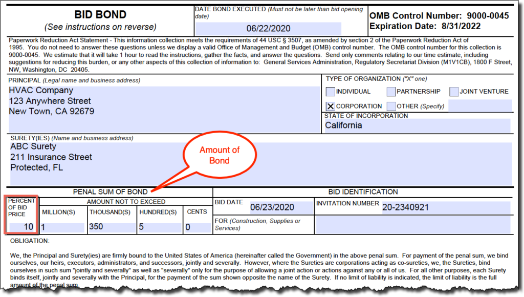
Bid Bonds
A Bid Bond will need to be provided by your surety in order to bid this project. This project requires a bid bond in the amount of 5% of your bid; often this is 10%. The bid bond ensures that you execute the contract at your bid price if you are the low bidder. In some event where you find yourself disqualified or you refuse to execute the contract, you can be liable for an amount equal to the difference between the amount of your bid and the next lowest bidder that the owner executes the contract with for the same scope of work, usually the next responsible lowest bidder.
Bid Bond
A bid bond is provided as a courtesy from your bonding company if you do enough work with them and have a good payment history.
Your liability should not exceed your bond amount. Failure to sign the contract and to furnish all items required by the bidding documents is ground for forfeiture of your bid bond.
A bid bond is provided as a courtesy from your bonding company if you do enough work with them and have a good payment history.
Performance and Payment Bonds
Federal, state and municipal projects usually require that you provide a Performance and Payment bond. The cost of this bond will need to be added to your proposal as your surety will charge you for this insurance. The performance and payment bond is to ensure the public entity that you will pay the material and labor expended for this project, along with payment to any subcontractors or vendors that furnished equipment or labor on your behalf. The cost of this bond will depend on your bonding capacity and history of paying such bonds.
Reservation of Rights
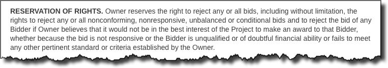
Reservations of rights allows the public entity the ability or right to reject any and all bids that it sees unfit according to the standards or criteria established by the owner.
Reservation of Rights
Bid Forms
Bid forms are a set of forms to be completed and sent in with your bid when bidding public projects. Privately funded projects don’t always use bid form, so you will prepare a proposal letter that contains all of your scope of work, exclusions, clarifications and assumptions.
Bid forms will include your price breakdown, alternate pricing, unit pricing, recognition of any addendums, performance and payment bond rate, along with your bid bond if required. Information about your company, including an authorized signature will be required.
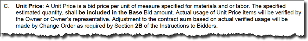
Unit Price
Does the project require you to submit unit pricing along with your bid? This can take some time to put together if you don’t already have some numbers generated. How much does your company charge if the owner decides to add 20 feet of 10” round ductwork and a ceiling diffuser, or to add a 12” x 12” fire damper? Unit pricing allows the owner to add or deduct items from the scope of work based on the unit prices you provide for each item. See the MEP Academy HVAC Piping Unit Pricing spreadsheet, that makes the creation of unit prices easy.
Unit Price
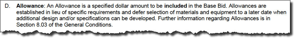
Allowance
Sometimes the owner will request that you include an allowance in your bid for a potential scope item that hasn’t been well defined yet, but for which the owner wants included in the cost proposal.
Bid Allowance
Alternate
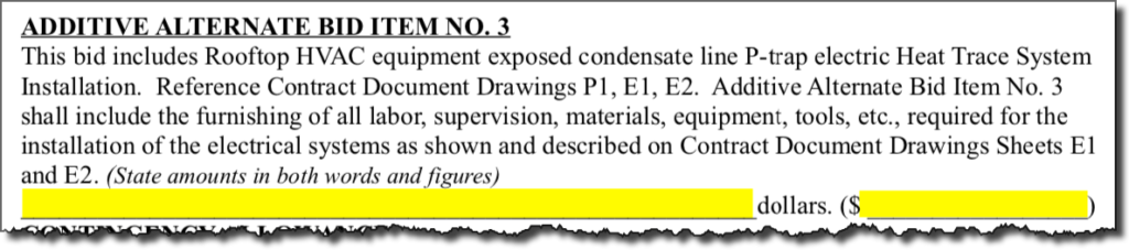
An alternate is for a specific scope of work or material not included in the base bid. The bid price for the Alternate is not included in the Base Bid amount. Alternates may be Additive or Deductive. The bid price for the Alternate should only represent the amount for the Alternate over and above the Base Bid work. See an example Additive Alternate below.
Additive Alternate 3
Addendum
Have any addendums been issued? All Addendums issued will become part of the contract, including any issued before the bid date. Addendums could be in the form of drawings, specifications or clarifications. It’s important to make sure you have the latest set of drawings and that all addendums are accounted for.
Also, it’s important that you assess the addendum for any impact it might have to cost, schedule or your vendors and subcontractors. Make sure to indicate that you have included the addendum in your proposal, and if it’s a public bid, then there should be a spot on the bid form for indicating the addendum number and date as shown below.
Addendum
Liquidated Damages
You won’t put any cost for this in your estimate as the intent is to complete the project as defined in the specifications to avoid incurring a liquidated damages penalty. This might be found in the section entitled progress schedule, where it states that if the project goes past its scheduled completion date, there will be damages assessed. This is a penalty for delaying the completion of the project, and is usually stated in so many dollars per day for every day that you pass the scheduled completion date, such as $500 per Day.
Here is what the government inserts into their contracts related to liquidated damages. They allow the governments contracting officer the right to determine what the penalty will be on any government contract that they are overseeing.
(a)If the Contractor fails to complete the work within the time specified in the contract, the Contractor shall pay liquidated damages to the Government in the amount of ____________ [Contracting Officer insert amount] for each calendar day of delay until the work is completed or accepted.
(b)If the Government terminates the Contractor’s right to proceed, liquidated damages will continue to accrue until the work is completed. These liquidated damages are in addition to excess costs of repurchase under the Termination clause.
Welcome to the course that will teach you how to Estimate HVAC Sheet Metal for the commercial industry. If you are mostly working in the HVAC residential industry, then this course will allow you to see what is involved to enter the commercial industry, while also giving you good estimating practices. In this course we will cover the steps needed to complete an HVAC Sheet Metal Estimate from material takeoff to field laboring.
The first section will cover the requirements needed to read engineered drawings, and what to look for in the plans and specifications that are applicable to the HVAC estimate. This includes understanding how to read the symbols used on drawings, and how to read the various CAD generated lines and the basic drawing layout. The building should be built just as its shown on the drawings and as indicated according to the specifications.
At the end of each section, there will be a short quiz to help you remember the material that was covered in that section.
The drawings that are used to bid the project will become part of the contract if your company is the winning bidder. So it’s important that you read through the drawings and specifications completely to ensure that you have all the cost covered to make for an accurate bid, one that will provide a profit for your company.
There are several different sets of drawings created for the construction or renovation of a building. The one that we will be focusing on are the Mechanical set, specifically the HVAC portion of the mechanical drawings.
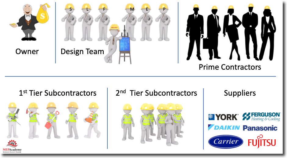
There are various players in any construction project. Depending on the delivery method, which there are three that are mostly used in construction: Plan and Spec, Design/Assist, and Design/Build. The parties to a construction contract are as follows.
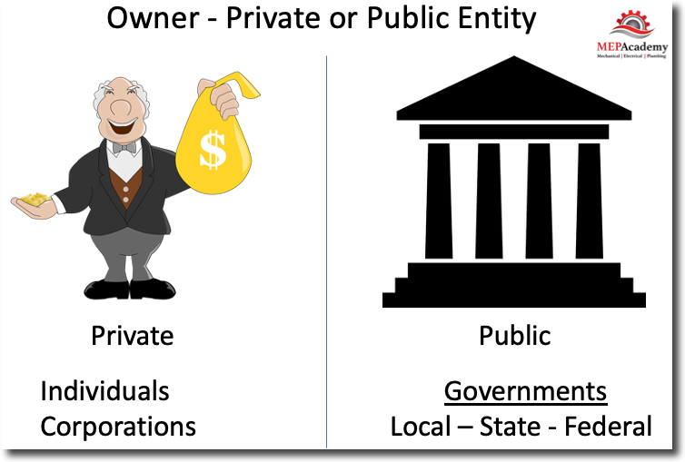
Project Owner (Private or Public)
The owner can be a public or private entity and is the one behind the reason or purpose for building or renovating a construction project. In the private sector this could be an individual or more likely a corporation. For the public sector this is usually your local, state or federal government which has more stringent and regulated bidding requirements then the private sector.
Ownership
The owner provides the money or can secure the funds for the project. They will hire the design team under the Plan and Spec delivery method, which includes the Architect and the associate trade engineers such as the Mechanical, Electrical, Plumbing and Structural engineers.
Plans and Specs Contractual Hierarchy
Design Team
Under a plans and specification delivery method, the private sector owner will hire an architect to carry out the design according to the owners directive and needs. The architect will hire all the other designers needed to provide a complete set of engineered drawings. These drawings will then be sent out with an (RFP) request for proposals from a list of approved general contractors.
Building Design Team
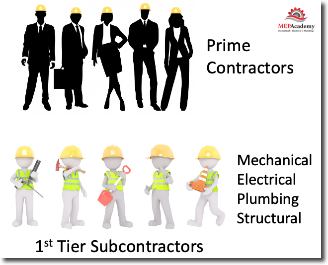
General Contractors (Prime Contractors)
The General Contractor will manage the construction project, using some or none of their own labor, and for which the owner contracts with for the construction of the project. The General Contractor will invite 1st tier subcontractors to provide bids on their respective trades, this would include the MEP (Mechanical, Electrical, Plumbing) trades, in addition to all the other trades.
1st Tier Subs
1st Tier Subcontractors
This is the level where the mechanical, electrical, plumbing and all other trade contractors will receive their subcontract agreement from the general contractor. There are instances when the contract will be directly with the owner, but in the most cases a General Contractor will be used in a plan and spec delivery method. This is the first tier of subcontractors to the general contractor, the next tier will be the subs of the subs.
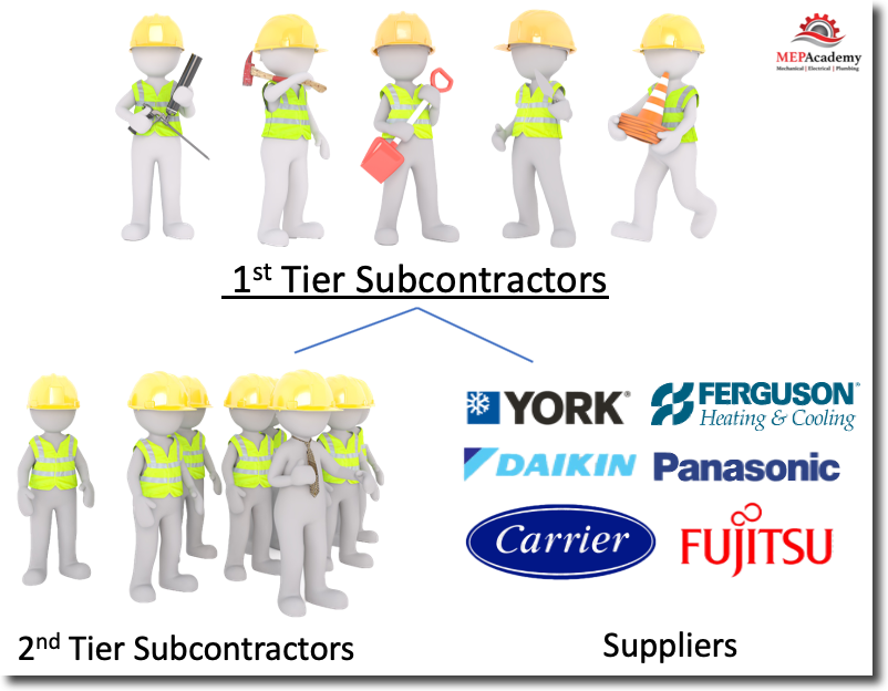
2nd Tier Subs and Vendors
2nd Tier Subcontractors
These are the contractors that get hired by the first tier subcontractors, which makes them the second tier subs to the general contractor as shown in the diagram. If you are the mechanical contractor, then you might hire an Water and Air balance company or an insulator to insulate the air conditioning ducts and piping.
Suppliers
You will also have agreements in the way of purchase orders with suppliers for the purchase of the equipment and materials needed to carry out the mechanical portion of the scope of work. During the bidding process they will provide quotations based on the plans and specifications as designed by the mechanical engineer.
Bidding Cycle
Estimating by Construction Activity/Construction Work Element
Before estimators can create a detailed estimate, projects must be broken down into smaller parts, so each part can be individually estimated. A subset of material, equipment, and labor estimates is created for each construction work element.
For example to install a 50 foot section of duct in a high bay area would require the following:
(Material) The material estimate identifies required quantities of duct, fittings, air distribution, and any sheet metal accessories.
(Rentals) The sheet metal estimate identifies that a scissor lift is required to install the hangers and ductwork.
(Labor) The sheet metal takeoff provides the quantity of hours and the number of man-days required to perform work.
(Fabrication) The takeoff identifies the pounds of sheet metal that has to be fabricated or purchased.
The following items should be provided to you by the salesperson or the general contractor, or whoever is responsible for bringing in the documents.
Drawings and specifications (Plans and Specs)
RFP (Request for Proposal) and a narrative description of the project’s scope
Bid Forms if applicable
Project schedule
Bid conference or job walk date
Bid date and time
Method of delivery for bid
What makes a Good Estimator?
The estimator must;
Visualize the separate operations of the job as the work would progress through the various stages of construction
Read, conceptualize, and obtain measurements from drawings
Have knowledge of mathematics, previous construction experience, and a working knowledge of all branches of construction
Have good judgement when determining what effects numerous factors and conditions will have on the construction of the project and what allowances should be made for each of them including labor adjustments.
Do accurate work and present it in a complete and organized format for an estimate review and handoff to operations if the project is successfully won.
SMACNA Company Spotlight – Black & McDonald
Black & McDonald, a Canadian based multi-trade contractor with offices across Canada and the United States. Watch this video to learn a little about how an experienced HVAC contractor conducts business. You can see their fabrication shop is setup to be efficiently run.
SMACNA Spotlights Black and McDonald Company
Prequalifying The Bid
It’s not feasible to bid everything that is available, as you will spend a lot of time and money chasing after work that you have very little chance of winning. This is why it’s important that you have some method to determine whether a certain project is worth the time and money to pursue.
Prequalifying is a set of questions that you ask of the opportunity to determine if it rates high enough to warrant pursuing it further. Here are some questions you might ask about the opportunity before you make a decision to pursue it.
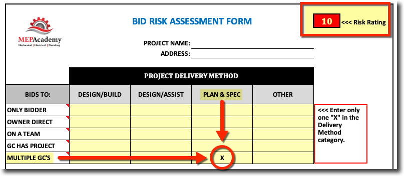
Bid Risk Assessment
Having some form of rating system will help you make a decision whether or not to bid a project based on some form of evaluation of the opportunity for success, such as the MEP Academy “Bid Risk Assessment” form which is part of the MEP Academy Estimating Spreadsheet.
Bid Risk Delivery Method
Project Delivery Method
There are several delivery methods from Design/Build to Plan & Spec. Each delivery method has more or less risk associated with it. The delivery method runs horizontally across the top header, and the entity accepting the bids runs vertically on the chart.
Design/Build means that you are responsible for the design and construction of the project. This means you either hire the mechanical engineer to be part of your team or you have in-house engineers that will design the project. This would make you the design-build contractor.
Design/Assist means that there is a 3rd party engineer that you will assist in the development of the materials and methods of construction and any value engineering ideas you have to make the project meet the owners budget and performance objectives.
The Plans and Specifications mean that there is a 3rd party engineer that designs the project and then mechanical contractor compete to build the project according to those plans and specs. You the contractor have no responsibility of the design, and should receive a change-order for any changes or corrections to the drawings that add cost to the project execution.
Design/Build projects allow you better control of the design, materials and methods of construction and so they usually allow for better margins or profits. This would be considered less risky and earn a lower score, meaning less risk on the assessment form and a better opportunity.
Plan and spec projects are usually more competitive and the opportunity for making profits that are comparable with the design-build delivery method are less, so this would rate a higher risk value.
Projects Bids to
The vertical column assesses who your competition is and who you are bidding to. Being the “Only Bidder” as shown on the top row would of course be the best position to be in as a bidder, so this would rate a low value or low risk factor.
The last row shows having “Multiple GC’s”, that is there would be more than one general contractor that you would have to submit your price to in order to have the greatest chance of winning the project. With more general contractors, there will be more mechanical contractors bidding, as each general will invite their typical three or more regular mechanicals to bid. This is the worst case scenario as the competition will be high and the margins driven lower in order to compete and win the project, so this gets the worst score in this category.
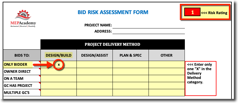
Looking at the above “Bid Risk Assessment Form” you see that bidding on a project that is Plan and Spec’s with Multiple GC’s will get you a high score of “10” points, which isn’t good. The risk assessment score is like a golf score, the lower the score the better, or in this case the less the risk the lower the score. Looking at the same form shown below, but this time we are bidding a Design-Build project and we are the only bidder, this gives you a score of “1”, which is good. Obviously this opportunity has less risk in the way of being the successful, which is what this form was created to determine.
Bid Risk Assessment Form in the MEP Academy Estimating Spreadsheet
How many other Sheet Metal bidders are there? You don’t want to be bidding against a large pool of bidders, unless you think that you have a lower overhead cost then the competitors.
How many General Contractors are bidding the project? If you are bidding to a general contractor, then you will need to know if they are bidding against a pool of other general contractors. The more general contractor there are bidding the project, the less chance you have of winning the project.
If there are four generals bidding and each one of them invites four mechanical contractors to bid the project, then it’s possible that you are one bidder out of sixteen possible sheet metal contractors. What’s the chance that you will win against fifteen other bidders. If you do win, what’s the chance you’ll make money having been the low bidder out of sixteen bidders?
Does the project have funding approved?
Is the schedule reasonable and do you have the field labor to perform the work when required?
Is the decision based on low price?
Are there any non-union bidders? If you are a union contractor trying to compete against non-union contractors you could be at a disadvantage on labor cost, unless the union grants some form of concession.
Do you have a relationship or experience working with the general contractor or owner?
Estimates that Lose Money
If you are an estimator long enough, you will have estimates that don’t make a profit as anticipated at time of the initial bid. This can be caused by many reasons. Some of the most common include;
Errors. Some of the causes of errors include not reading all the specifications for the requirements, or reviewing all the details and notes on the drawings. Errors can occur because of being rushed to get a project bid without the time to do your due diligence with all the bid documents.
Labor Productivity in the field may not have produced according to the assumption made at bid time. This could be due to unforeseen project conditions that increased the difficulty for the installers to hit the labor productivity factors assumed at bid time in the estimate.
Was the estimate short on material or equipment cost?
Was there adequate rental equipment cost in the bid, including the proper duration or the time required for its use?
Was the project schedule extended, requiring additional cost for extended general conditions?
Whatever the reason, you should have a closeout meeting with the project management team to determine a better approach on the next project that poses similar risk possibilities.
Sometimes it’s just not possible to predict how a certain general contractor or owner will manage the construction project, and how that will impact your labor. By having a strong project management team on the project to ensure that any legitimate change order is procured can help minimize or mitigate the risk of poor management of the construction by the general contractor or owner.
Bidding on Federal Construction Projects
All GSA (General Services Administration) design and construction contracting opportunities are advertised on the Federal Business Opportunities (“FedBizOpps“). To receive drawings and specifications for projects, contractors must be registered in the System for Award Management (SAM) system and in FedBizOpps, as drawings and specifications are usually issued electronically there. Announcements will contain instructions on obtaining classified drawings and specifications which are not distributed through FedBizOpps. The following areas are included in construction.
Beginning an Estimate
Deciding on whether to bid a project or not is sometimes beyond the estimators role. Often, a salesperson, contract executive, construction manager, Vice President, owner or some other individual will make the decision of whether or not to proceed on a bid. Some of the factors that go into the decision could be;
What is the availability of our staff to run this project?
What is the projected availability of field personnel to install the project according to the project schedule?
Who is the competition?
Who are you bidding to?
Do they pay on time?
Do they manage a project in a proficient way?
Are there multiple general contractors?
Once the decision has been made to proceed with a project it is best to begin by following the procedures outlined in this course, you will ensure that each and every estimate that you assemble will be done in the most efficient and fail safe method, thus avoiding costly mistakes.
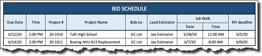
After the decision is made to pursue a project, then there should be somewhere that the name, date and time is displayed for the estimating team and for vendors that visit your office.
Below is the minimum information that you should have when tracking bids and their due dates.
Due Date & Time: When is the bid due and at what time? Depending on whether the bid is public or private can make a big difference on the actual submission time. Most public entities won’t accept bids that are submitted a minute late, while private companies have more leeway.
Project Number: This should match the project number entered on the bid log above in order to track all the records related to the bid.
Project Name: Usually this is the name on the drawings and specifications and what everyone will referred to, especially working with your vendors and subcontractors.
Estimating Bid Schedule
Bids To: List who the bid will be sent to. If it’s a public bid then there could be specific instructions in the bid documents on how to address the envelope and how many copies are required.
Lead Estimator: If you have multiple estimators, then list the estimator assigned to lead the estimate.
Job Walk: List the date and time of any job walks. There are some job walks that are mandatory in order to submit a bid. At these job walks or project conferences there will be a sign-in sheet to confirm to everyone who was present at the mandatory meeting.
RFI Deadline: You will need to study the drawings and read the specifications to derive at any questions that you might want to submit as an RFI (Request for Information). RFI’s help clarify items on the drawings, specifications or from the job walk site visit.
Bid Log
Next you will want to record the project into an estimate log and assign it a proposal number. This will allow you to provide a year-end report on various parameters related to success ratios, project types and delivery methods.
Bid Log
Estimating Bid Log
After you finish the estimate, you should record the pertinent information into a bid log. If you are using one of the many software programs for tracking bids, then this would be automated with that program.
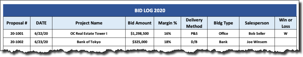
The bid log should be something similar to the above. The bid log is used to keep track of the order in which projects arrive into the estimating department and for reference when looking back to check an old estimate.
Proposal #: Put the estimate number on all documents related to that bid, especially the estimate spreadsheet and proposal. The numbering system shown above includes the last two digits of the year, followed by the number of the project bid in that year. As shown in the example above (20-1001), this bid was the first bid in the year 2020. You should create a estimate tracking system to keep track of the estimates that you work on. This will make it easier for you to reference at a later date.
Date Received: Enter the date you received the documentation and the name of the project.
Bid Amount and Margin After the project bids you can enter the bid amount, margin and latter if you won or lost the project. You can include any information that you deem important for your company to track.
Delivery Method: P & S is the abbreviation for Plans & Specifications and is your typical Design-Bid-Build process of construction. D/B would indicate Design-Build, a much different process than plan and spec. This course will cover the P&S (Design-Bid-Build) process, but many of the procedures are applicable to both. See our other course on Design/Build.
Building Type: Tracking the building type is for historical reasons. Often your looking for a project to compare an estimate that is of a similar building type.
Salesperson: Indicate the individual that brought the project into the estimating department or the individual that is responsible for presenting the project proposal to the company receiving the bids.
Wins and Losses: The bid log will help to total the dollar amount of the projects won and loss for the year, and the success ratio.
Bid Notification
There are a lot of software programs available that automate vendor and subcontractor notification.
List the name of the project, the engineer and the bid date. The reason the engineer is important is because some vendors assign their salespeople according to who the engineering firm is. The vendor bid notification should be filled out early in the process, so that everyone that needs to provide pricing has a reasonable amount of time to do so.
Poor estimating practice is to notify the vendor and subcontractors late in the bidding process, forcing them to be hurried in preparing their bid. The less time you give your vendors and subcontractors to prepare the more likely that their price will be uncompetitive.