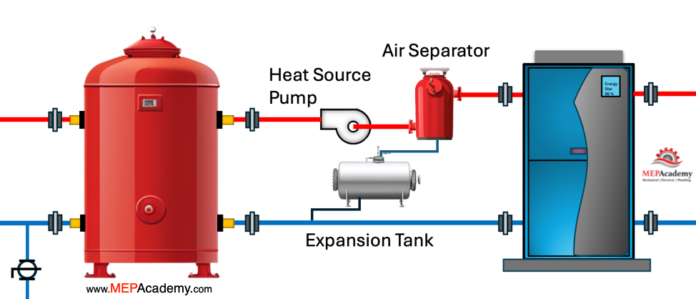
A buffer tank acts as a thermal energy battery for heating hot water or chilled water systems that lack enough water volume during low load conditions to avoid short cycling. They can be used with geothermal heat pumps, chilled water systems, low-mass boilers, and low mass radiation systems. We’ll show you how they work and a couple examples of how to size them for a heating hot water and chilled water system. See Calculations below.
If you prefer to watch the video of this presentation, then scroll to the bottom.
A buffer tank serves several important functions.
Preventing Short Cycling
Buffer tanks prevent short cycling of boilers, heat sources and chilled water systems. Short cycling occurs when the heating or cooling system turns on and off rapidly due to small fluctuations in demand. This can be inefficient and cause wear and tear on the heating and cooling equipment and is one of the top causes of failure in a heating system.
The buffer tank provides a reservoir of heated water, allowing the system to operate more steadily. A buffer tank can help prevent a compressor from short cycling during low load in a Geo-thermal or chilled water system.
Here is what happens during low load conditions. The boiler or compressor turns on and quickly satisfies demand, shutting off just as quickly because of low load condition. This short cycling of on and off continues under low load conditions creating additional wear on the boiler or compressor. So, by adding additional load and water volume with a buffer tank, this short cycling period is reduced or eliminated during low load periods.
A buffer tank is basically an insulated storage tank that adds additional mass to absorb or reject heat during low load conditions to prevent short cycling of the equipment, and to prevent accelerated equipment wear.
Sizing Buffer Tanks
Here are two different formulas, one for a geothermal heat pump system, and another for a chilled water system.
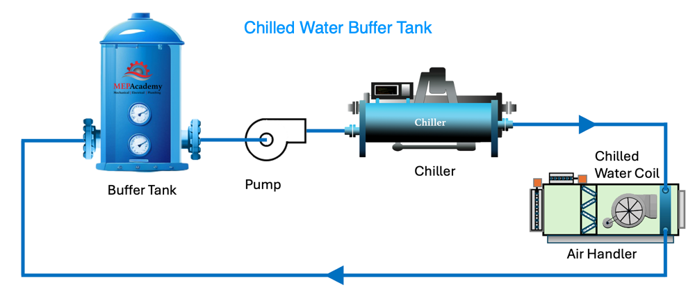
Chilled Water Buffer Tank Sizing
The following formula is offered by one manufacturer, and any calculations you make should be confirmed by a Mechanical Engineer or the manufacturer.
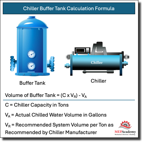
Volume of Buffer Tank = (C x VR) – VA
C = Total Chiller Capacity in Tons
VA = Actual Chilled Water Volume in Gallons
VR = Recommended System Volume per Ton as Recommended by Chiller Manufacturer
We’ll need to make up some values for this example. Let’s say we have a small chiller of 100 Tons, and the manufacturer requires 6 gallons per ton minimum volume. If we use this information, we can derive a value at which anything below that value would require a buffer tank.
100 tons x 6 Gals. /Ton = 600 Gallons minimum system volume.
If the actual system volume is less than 600 gallons, then a buffer tank becomes required. Let’s say our system volume is 480 gallons.
Chilled Water Buffer Tank Calculation
Chiller Buffer Tank Volume = (100 Tons x 6 Gals. / Ton) – 480 Gallons = 120 Gallons
From the calculation, we can see that for every gallon the existing system total is under 600 gallons, another gallon is added to the tank capacity to provide the minimum required of 600 gallons of system volume.
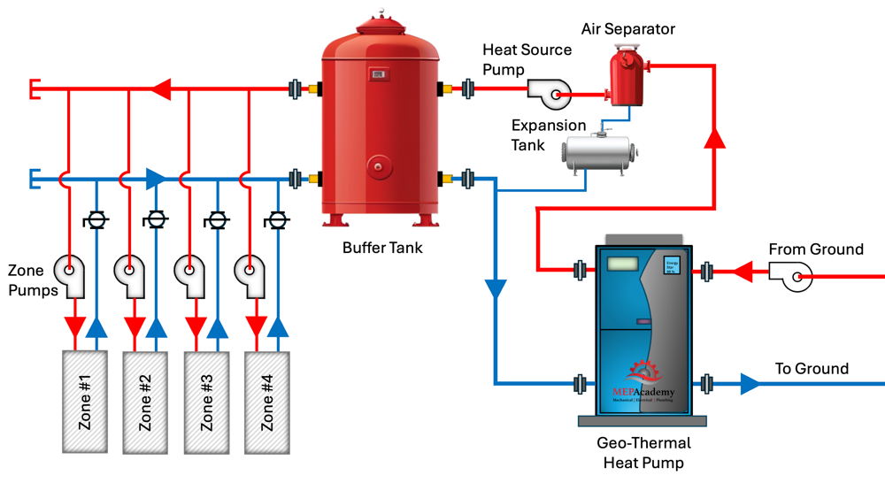
Water Source Heat Pump Buffer Tank Sizing
The following formula is offered by one manufacturer, and any calculations you make should be confirmed by a Mechanical Engineer or the manufacturer. The calculation is meant to allow for the Boiler or Source of Heat to run for a minimum amount of time before cycling off.
Buffer Tank Calculation Formula
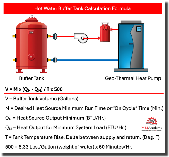
V = M x (QH – QM) / T x 500
- V = Buffer Tank Volume (Gallons)
- M = Desired Heat Source Minimum Run Time or “On Cycle” Time (Min.)
- QH = Heat Source Output Minimum (BTU/Hr.)
- QM = Heat Output for Minimum System Load (BTU/Hr.)
- T = Tank Temperature Rise, Delta between supply and return. (Deg. F)
- 500 = 8.33 Lbs./Gallon (weight of water) x 60 Minutes/Hr.
For our example let’s assume that we have a heat pump that outputs a minimum of 60,000 BTU/Hr., and that the manufacturer recommends a minimum cycle time of 10 minutes, and that the smallest zone is 9,000 BTU/Hr., and the radiant heating zones allowable temperature differential is from 90 to 100 (F). If zones 1 through 3 were off, and only zone 4 was running at 9,000 BTU/Hr. our calculation would look like this.
Hot Water Buffer Tank Calculation
V = 10 minutes x (60,000 – 9,000) / (100 – 90) x 500 = 102 Gallons
For more information see our article on our website which goes into greater detail about the benefits of using buffer tanks.
Other Benefits of a Buffer Tank
Temperature Regulation
The tank helps maintain consistent water temperature in the system by absorbing excess heat or releasing stored heat as needed.
Increasing System Efficiency
By reducing the frequency of the boiler or compressor cycling, buffer tanks can improve overall system efficiency. They allow boilers and chillers to operate at their most efficient levels for longer periods, reducing energy consumption.
Accommodating Variable Demand
In systems with fluctuating demand for hot water, such as those serving large buildings or facilities, buffer tanks provide a buffer of stored hot water that can be drawn upon during peak demand periods. This helps ensure a consistent supply of hot water without putting excessive strain on the heating equipment.
Protection Against Stratification
Buffer tanks help prevent stratification of water temperature within the heating system. This occurs when hot water rises to the top of the system while cooler water sinks to the bottom, resulting in uneven temperatures and reduced system efficiency. The tank allows for mixing of water to maintain more uniform temperatures throughout the system.
Overall, buffer tanks play a crucial role in optimizing the performance, efficiency, and reliability of heating hot water systems in various applications, including commercial buildings, hospitals, and other facilities.


