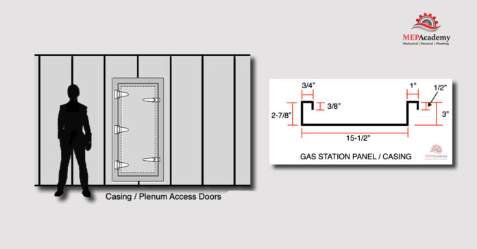
Chapter #8 – Sheet Metal Casings and Plenums
There are projects that will require large plenums or casings, such as in built up system where components of the air conditioning system are bought in separate pieces and then assembled. In order to build these larger sheet metal plenums you will need to use additional methods of construction than those for traditional duct fabrication. These larger sheet metal plenums are often built the size of a small or large room and house fans, coils, filter banks and dampers. These large plenums will have doors to provide access to the various sections.
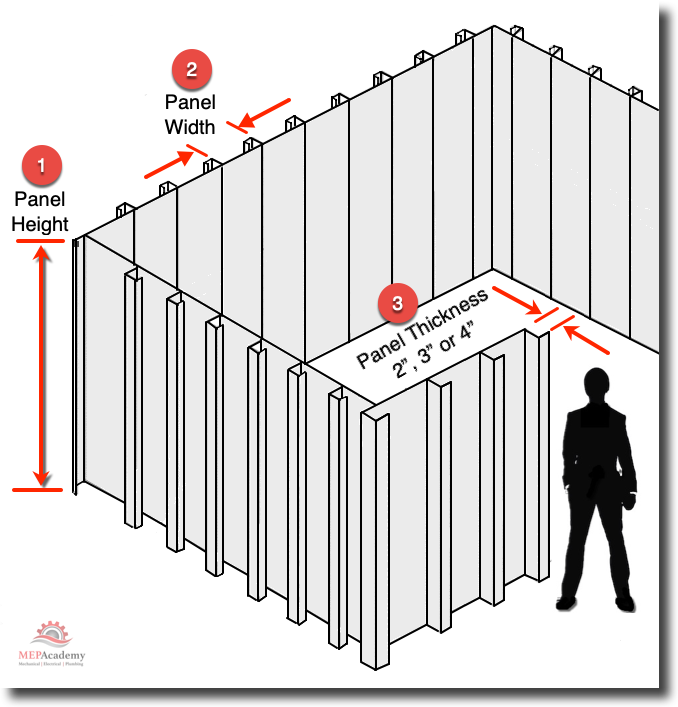
The purpose is to provide an area for supply, return or exhaust air to accumulate before or after the fan section, so they will need to be built to the appropriate pressure class. In some cases walls and floors of the building will make up one or more of the sides of the plenum, requiring that the plenum be sealed tight at this connection. Any penetration of the casing or plenum will require proper sealing to prevent leakage or infiltration.
SMACNA states that all ductwork fabricated on the suction side of the fan are built to 2 in. wg (500 Pa) pressure classification, while the discharge matches the design pressure classification of the system. If the casing or plenum exceeds negative 3 in wg (750 Pa) then you may build according to SMACNA’s Rectangular Industrial Duct Construction Standards.
As the height or width (#1) of the Casing/Plenum increases, the thickness (#2) of the material, Steel Angles (#3) and Standing Seams (#4) will increase as shown in SMACNA Figure 9-1 below.
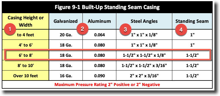
Construction methods include the use of Standing Seams, Gas Station Panels or TDC/TDF Flanges. As can be seen from the chart above, as the height increases so does the requirement for a thicker gage material, larger angle and standing seam. Openings in the plenum or casing will be framed with angle to provide reinforcement.
Gas Station Panel Roll Forming Machine
There are not many fabrication shops that own their own Gas Station Panel Roll Forming Machine because the cost of these machine are high compared to the volume of this type of sheet metal required by the average commercial construction company. Unless your company builds a lot of large built up systems, then chances are they won’t own one of these, but will use other methods that are less productive but yet provide a similar product.
The below chart shows what determines the requirements for building a large Plenum or Casing. The columns are as follows: Span (#1) defines the Panel Height of the casing, Panel Gage (#2) defines the thickness of the metal, Depth (#3) is the Panel Thickness (2”, 3” or 4”), Load Class (#4) is determined by the pressure class (Static Pressure wg.) of the system.
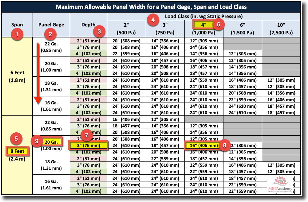
For example in the chart above, if you had a Panel Span (#5) of 8 feet and a system Static Pressure (#6) of 4” wg., and you wanted to use a Panel Depth (#7) of 3” with a Panel Width (#8) of 16”, this will inform you to use a Panel Gage (#9) of 20 Ga. The above chart includes additional Panel Span Heights: 10’, 12’, 14’, 16’ and 18’, (See SMACNA Manual for Additional Chart Data)
Sheet Metal Fabrication shops that have a roll forming machine will want to make efficient use of the coil sizes in inventory without waste. The below image shows a panel that was made from a standard 24” coil without any waste. If you add up all the dimensions of the below panel you will come up with 24”. Although the panel width in the below example is only 15-1/2”, you would use the 16” panel width and 3” wide column for all your panel requirements.
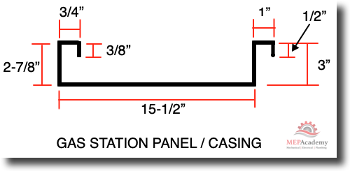
Many of these roll forming machines are used to fabricate metal roofing panels on large industrial projects.
The casing can be lined with insulation and a solid (Double Wall) or perforated sheet metal interior skin. There are vendors, who sell prefabricated insulated plenum wall panels, but they are usually more expansive then those that your shop can fabricate or that the shop you purchase your duct from can fabricate for you.
Estimating Built Up Casings / Plenums
In order to determine how much sheet metal is included in the design you will need to measure the linear feet of the Panel walls and ceilings across its Face Area. As shown below a typical Panel Width of 15-1/2” when stretched out or flatten, the actual width is 24”, which includes all the sides and parts of the metal that was rolled formed. The stretch-out of the panel above would look like the panel below. This would allow the fabrication shop to use a standard 24 inch wide panel or coil.
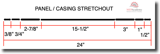
Example:
20 linear feet of a 16” (15-1/2”) Panel Width would be equivalent to much more because an additional 8” or 50% of the metal is consumed in the roll forming process using a 24” sheet metal coil.
#1 Panel Height 8 Feet
#2 Casing Wall Width 25.83 Feet (310 Inches)
#3 Casing Wall Width 5 Feet
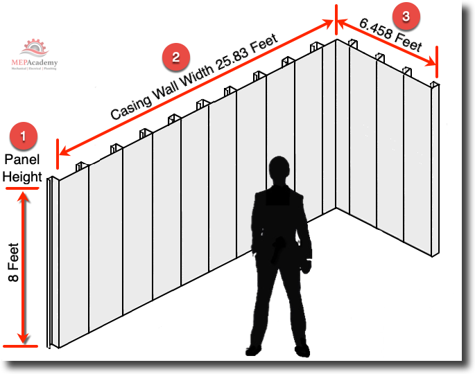
A rough way to estimate how much panel material there is in the above casing walls is as follows;
Step #1 (Calculate Quantity of Panels in Casing Wall #2)
The first step is to determine how many Full Height Panels (#1) are required in Casing Wall Width #2 by turning the total footage into Inches and then dividing by the Panels Face Width.
25.83 feet x 12 inches/Foot = 310 Inches
310 Inches / 15-1/2” Inches/Panel Width = 20 Panels
Step #2 (Calculate Quantity of Panels in Casing Wall #3)
6.458 feet x 12 inches/Foot = 77.5 Inches
77.5 Inches / 15-1/2” Inches/Panel Width = 5 Panels
Step #3 (Calculate the Total Square Feet of Material)
Sum the total quantity of Casing Panels.
20 Panels + 5 Panels = 25 Casing Panels
Figure the Total Stretch-out Square Footage based on Panel Face Width and Material Width used to create the panel. The width of the material is determined by the wall width (2”, 3” or 4”). In the example above we were using a 24” coil width with a 3” Casing Panel Width, so we will use 24” for a stretch-out material width. Remember that the visible Face Panel Width is only a portion of the total material that you see or use in creating a panel, the rest is used in making the roll formed panel width (2”, 3” or 4”).
Using Panel Height (8 Feet) we can now calculate the total Square Feet of the material required to make this plenum or casing.
25 Panels x 24” width/Panel = 600 Inches / (12 Inches/Foot) = 50 Feet total width of material stretched out.
50 Feet (Width) x 8 Feet (Panel Height) = 400 Ft2
Answer 400 Ft2 of Material
Step #4 (Determine Total Poundage of Material)
Using the Maximum Allowable Panel Width chart above, we can see that with a Panel Height of 8 feet (#5) and a width of 3” (#7), and a static pressure of 4” wg, we find that using a panel width of 16 inches (#8) we get the required sheet metal gage of 20 ga. Note that we are using a panel width of 15-1/2”, and not 16”. The chart allows any size smaller then that listed, but not one greater than the listed panel width. The reason we are using 15-1/2 inches is that allows for you to use a perfect 24” sheet metal coil are flat stock without any waste.

Now that we know the Gage and the square footage of the material required to make the panels we can determine the total poundage.
400 Ft2 x 20 ga (1.656 Lbs/Ft2) = 400 x 1.656 = 662.4 Lbs
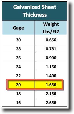
Whenever you have a bunch of calculations to perform its best to use a computer program or application for this like Microsoft’s Excel program.
There are additional materials when figuring out the cost of a Casing or Large Plenum, such as Angles, anchors, gaskets, sheet metal screws, Access Doors, etc . There are also other methods of fabricating casings, but these are the ones illustrated in the SMACNA manual.
Access Doors
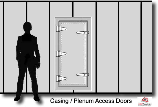
With large built up HVAC systems there will be a need for access doors in the plenum walls to provide a means for maintenance staff to replace the filters, clean the coils or to replace fan motors. SMACNA prefers that you limit the amount of doors so as to maintain the integrity of the plenum.
Now let’s look at chapter #8 on how to figure shop fabrication productivity.
- Chapter #1 – Introduction to Sheet Shop Fabrication
- Chapter #2 – Sheet Metal Materials
- Chapter #3 – Sheet Metal Coil Line
- Chapter #4 – Plasma Cutting Table
- Chapter #5 – Spiral Machine
- Chapter #6 – Sheet Metal Seams
- Chapter #7 – Sheet Metal Joints
- Chapter #8 – Casings and Plenums
- Chapter #9 – Sheet Metal Shop Fabrication Productivity


