How to read a refrigerant chart. The heat transfer properties of refrigerant is the key ingredient used in the HVAC industry for cooling. Reading a refrigerant pressure-enthalpy (P-H) chart allows you to analyze and understand the thermodynamic properties of a refrigerant at different pressures and temperatures. Being able to read a refrigerant chart allows you check the health of a refrigerant system.
If you prefer to watch the video of this presentation then scroll to the bottom or click on the following link: How to Read a Refrigerant Chart
Here’s a step-by-step guide on how to read a refrigerant P-H chart:
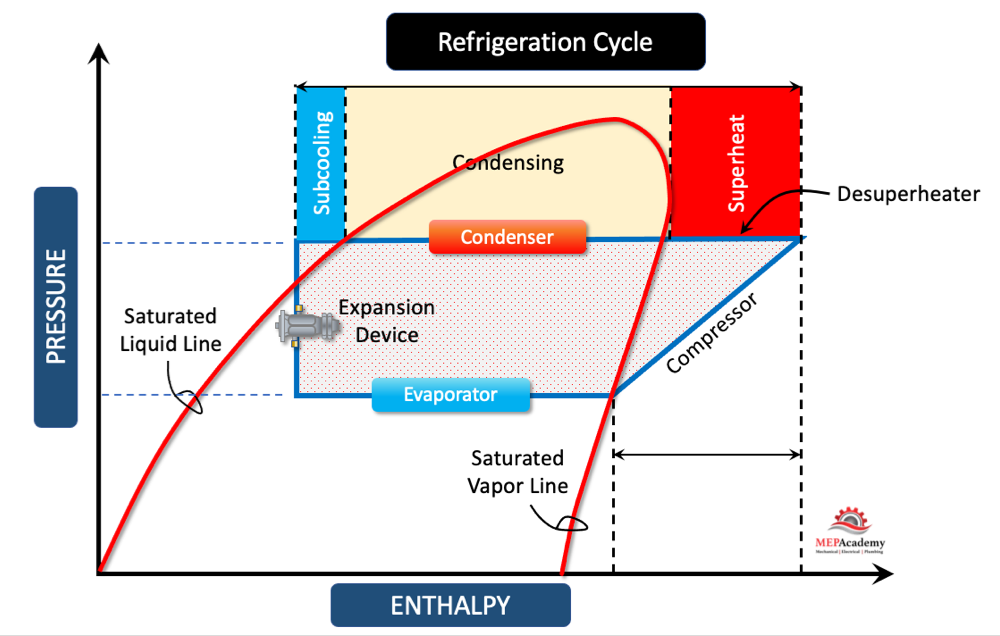
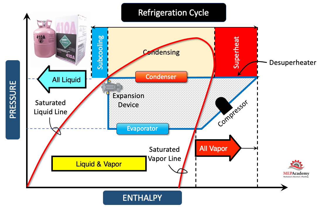
1. Understand the axes: The P-H chart typically has the pressure (P) axis on the y-axis and the enthalpy (H) axis on the x-axis. The pressure is usually measured in units like psi, kPa, or bar, while the enthalpy is measured in units like Btu/lb, kJ/kg, or kcal/kg.
2. Identify the refrigerant: Determine which specific refrigerant is being represented on the chart. Different refrigerants have their own unique Pressure Enthalpy charts, so make sure you have the correct one for your refrigerant of interest.
Checkout Refrigerants here3. Locate the pressure: Find the desired pressure on the y-axis of the chart. Trace a horizontal line from that pressure value until it intersects with the graph. If you want to use gauge pressure then add atmospheric pressure.
4. Determine the Temperature: Once the horizontal line intersects the graph, locate the corresponding temperature value on the 100% saturated liquid line or 100% saturated vapor line. The temperature in-between these two saturation lines is constant and runs horizontally, while outside this bubble area the temperature lines run vertically. This temperature represents the saturation temperature of the refrigerant at the given pressure.
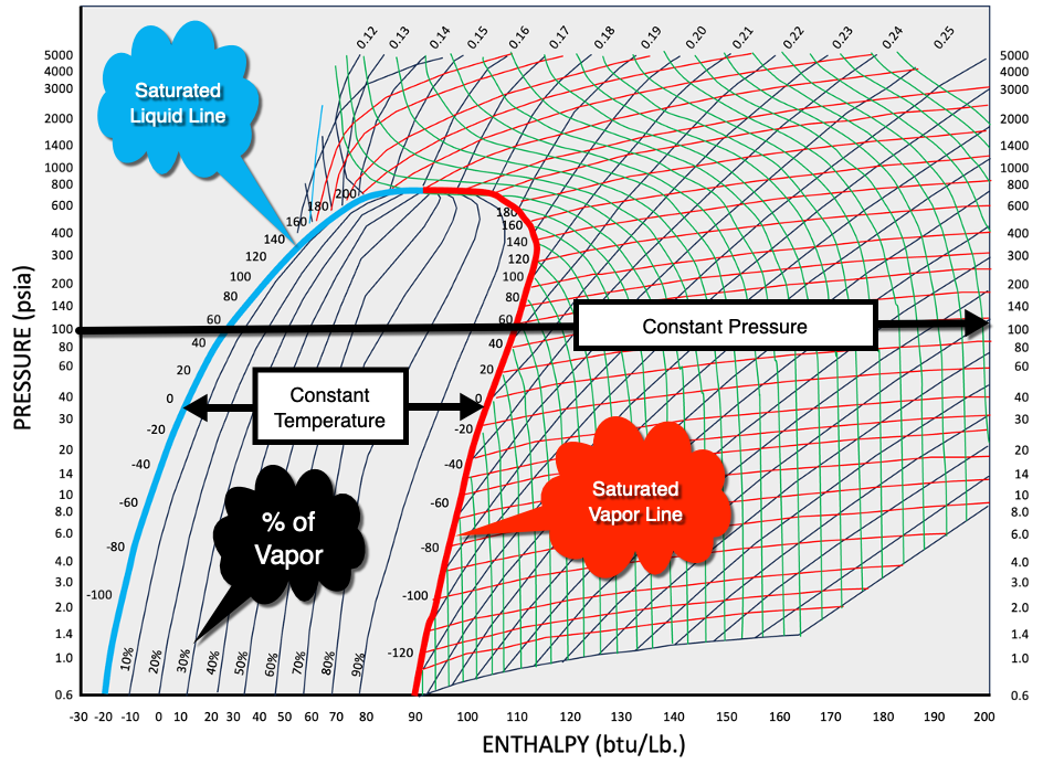
The saturation temperature for a refrigerant refers to the temperature at which the refrigerant exists in a state of equilibrium between its liquid and vapor phases at a specific pressure. It represents the temperature at which the refrigerant will undergo a phase change from liquid to vapor (to boil) or from vapor to liquid (to condense).
The Constant Quality line runs vertically within this bubble area indicates the percentage of refrigerant that is in the vapor state. You can see as the constant quality line leaves the saturated liquid line and approaches the saturated vapor line, more and more of the refrigerant is turned into vapor, until it’s 100% vapor at the saturated vapor line.
5. Analyze enthalpy:
Analyze enthalpy: From the intersection point, trace a vertical line downward until it intersects with the enthalpy scale on the x-axis. This gives you the specific enthalpy value for the corresponding pressure and temperature.
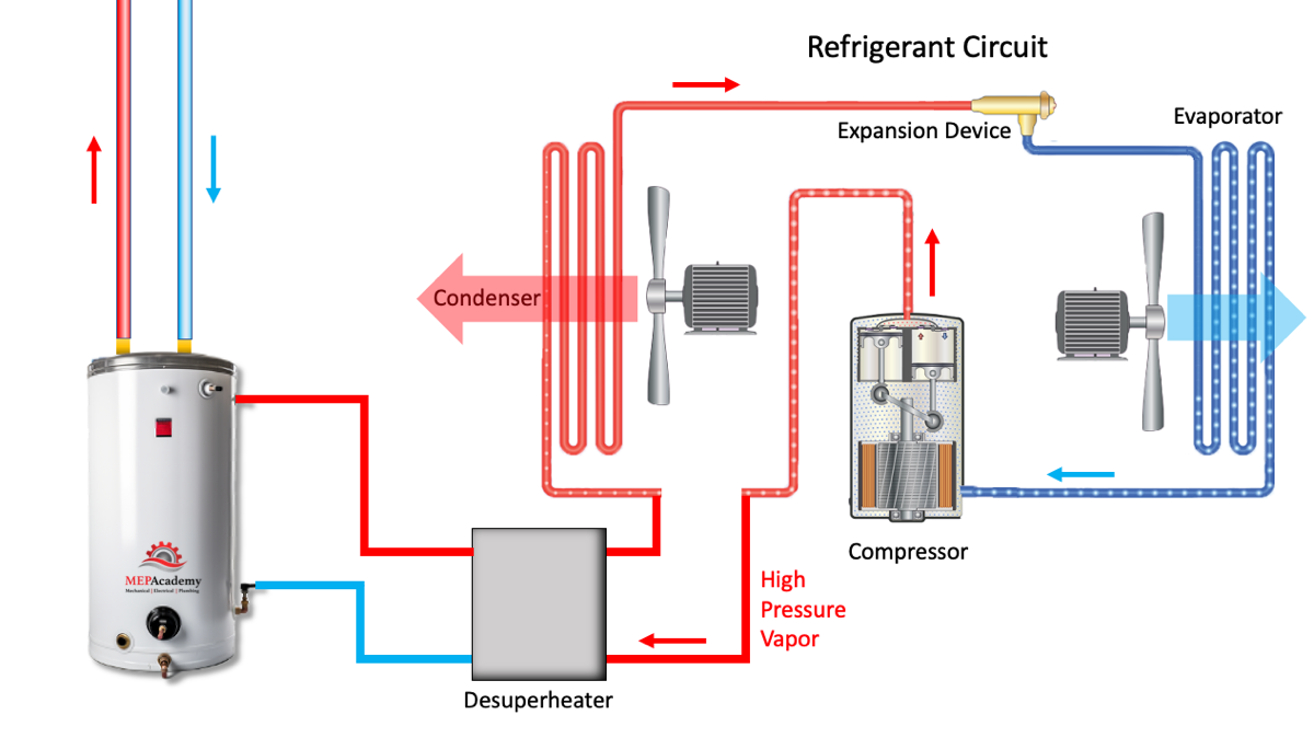
The constant temperature and pressure line is where the evaporator turns liquid refrigerant into vapor. When it reaches the saturated vapor line it should be 100% vapor as this is where it will enter the compressors which only works with vapor. The compressor will raise the pressure and temperature up to the condensing temperature and pressure. This small section beyond the saturated vapor line is where de-superheating takes place. This runs from the compressor discharge until it intersects the saturated vapor line, and from there it remains at a constant temperature. See our video on Desuperheating.
Here the condenser line runs from the exit of the compressor until it reaches the expansion valve. In order to reuse the cooling effect of the refrigerant, we’ll need to lower its temperature. This is done by lowering the pressure through the expansion device. As refrigerant pressure is related to temperature. As the refrigerant liquid enters the expansion device some it flashes causing the temperature to lower. You can see that at the entrance to the evaporator a certain percentage of the refrigerant has already been evaporated and turned into vapor, approximately 35% in our example.
6. Interpret properties: Using the enthalpy value, you can gather important information about the refrigerant. For example, you can determine the refrigerant’s state (saturated liquid, saturated vapor, or superheated vapor) and calculate its specific heat capacity or other thermodynamic properties.
7. Additional information: Some P-H charts may include additional data points or curves, such as lines of constant entropy or lines representing superheated vapor or subcooled liquid regions. Familiarize yourself with any such features to extract more information from the chart.
Remember, reading a P-H chart requires understanding of the thermodynamic properties and behavior of refrigerants. It’s recommended to consult relevant textbooks, manuals, or guides to gain a deeper understanding of how to interpret and use these charts effectively.
The bubble point on a refrigerant pressure-enthalpy (P-H) chart refers to the state at which a refrigerant undergoes a phase change from a liquid to a vapor (boiling) when pressure is held constant. It represents the saturation curve or the boundary between the liquid and vapor phases of the refrigerant.
When reading a P-H chart, the bubble point is the point on the chart where the refrigerant is in a saturated liquid state. It occurs at a specific pressure and temperature combination where the refrigerant starts to boil and transition from a liquid phase to a vapor phase.
Superheat
Superheat, in the context of refrigeration systems and a refrigerant pressure-enthalpy (P-H) chart, refers to the temperature increase of a vapor refrigerant above its saturation temperature at a given pressure. It represents the amount of sensible heat added to the refrigerant after it has completed the phase change from liquid to vapor.
On a P-H chart, the superheat region is located beyond the saturation curve, where the refrigerant is in a vapor state and has a temperature higher than its saturation temperature at a specific pressure. The superheat region is typically represented by lines or curves that indicate constant levels of superheat.
Measuring and controlling superheat is crucial in refrigeration systems to ensure optimal performance and prevent potential issues. By monitoring and adjusting the superheat, technicians can achieve efficient and reliable operation of the system.
The superheat value is important for several reasons:
1. System efficiency: Proper superheat ensures that the refrigerant completely evaporates in the evaporator coil before it reaches the compressor. This maximizes the system’s cooling capacity and energy efficiency.
2. Compressor protection: Superheat helps prevent liquid refrigerant from entering the compressor, which can cause damage due to inadequate lubrication and potential compressor failure.
3. Temperature control: Superheat helps maintain a consistent temperature in the evaporator coil, ensuring proper cooling and preventing frost or ice formation.
To determine the superheat value on a P-H chart, locate the point on the chart that corresponds to the operating pressure and temperature of the refrigerant in the superheated vapor state. The difference between this temperature and the saturation temperature at that pressure represents the superheat value.
By monitoring superheat and adjusting system parameters such as refrigerant flow, evaporator pressure, and temperature settings, technicians can optimize the performance and efficiency of refrigeration systems.
Sub-cooling
Subcooling, in the context of refrigeration systems and a refrigerant pressure-enthalpy (P-H) chart, refers to the temperature decrease of a liquid refrigerant below its saturation temperature at a given pressure. It represents the amount of sensible heat removed from the refrigerant after it has completed the phase change from vapor to liquid.
On a P-H chart, the subcooling region is located below the saturation curve, where the refrigerant is in a liquid state and has a temperature lower than its saturation temperature at a specific pressure. The subcooling region is typically represented by lines or curves that indicate constant levels of subcooling.
Sub-cooling is important in refrigeration systems for several reasons:
1. System efficiency: Proper subcooling ensures that the liquid refrigerant is condensed and remains in a liquid state before entering the expansion device. This maximizes the system’s cooling capacity and energy efficiency.
2. Expansion device performance: Subcooling helps optimize the operation of the expansion device (such as a thermostatic expansion valve) by providing a stable liquid refrigerant flow rate and improving the accuracy of the refrigerant metering process.
3. System stability: Subcooling helps maintain a stable refrigerant flow and temperature control, preventing issues such as flashing or unstable operation in the evaporator.
To determine the subcooling value on a P-H chart, locate the point on the chart that corresponds to the operating pressure and temperature of the refrigerant in the subcooled liquid state. The difference between this temperature and the saturation temperature at that pressure represents the subcooling value.
By monitoring subcooling and adjusting system parameters such as condenser pressure, refrigerant flow, and condenser temperature settings, technicians can optimize the performance and efficiency of refrigeration systems while ensuring the proper operation of key components.
Latent Heat of Fusion
The latent heat of fusion for a refrigerant refers to the amount of heat energy that must be added or removed from the refrigerant to cause a phase change from a solid to a liquid state, or vice versa, at a specific temperature and pressure.
When a refrigerant undergoes fusion, which is the transition from a solid to a liquid state, the latent heat of fusion represents the heat energy required to break the molecular bonds and convert the refrigerant from a solid (usually in the form of ice) to a liquid without a change in temperature. Similarly, when a refrigerant solidifies from a liquid to a solid state, the same amount of heat energy is released.
The latent heat of fusion is a characteristic property of each substance, including refrigerants, and is typically expressed in units such as joules per kilogram (J/kg) or calories per gram (cal/g). It is important to note that the latent heat of fusion is specific to the refrigerant being used.
Knowing the latent heat of fusion is significant in refrigeration and air conditioning applications, particularly when dealing with phase change processes such as melting or freezing. Understanding this property helps in sizing components like evaporators and condensers, determining the amount of energy required for phase changes, and predicting the thermal behavior of the refrigerant during these transitions.
It’s worth noting that not all refrigerants exhibit a solid phase at typical operating conditions. Some refrigerants, such as hydrofluorocarbons (HFCs) and hydrochlorofluorocarbons (HCFCs), do not undergo a solid-liquid phase change but instead transition directly between vapor and liquid states. In such cases, the concept of latent heat of fusion may not apply.
Latent Heat of Vaporization
The latent heat of vaporization for a refrigerant refers to the amount of heat energy that must be added or removed from the refrigerant to cause a phase change from a liquid to a vapor state, or vice versa, at a specific temperature and pressure.
When a refrigerant undergoes vaporization, which is the transition from a liquid to a vapor state, the latent heat of vaporization represents the heat energy required to break the intermolecular forces and convert the refrigerant from a liquid to a vapor without a change in temperature. Conversely, when a refrigerant condenses from a vapor to a liquid state, the same amount of heat energy is released.
The latent heat of vaporization is a characteristic property of each substance, including refrigerants, and is typically expressed in units such as joules per kilogram (J/kg) or calories per gram (cal/g). It is important to note that the latent heat of vaporization is specific to the refrigerant being used.
Knowing the latent heat of vaporization is crucial in refrigeration and air conditioning applications as it helps in sizing components such as evaporators and condensers, determining the amount of energy required for phase changes, and predicting the thermal behavior of the refrigerant during these transitions.
The latent heat of vaporization also plays a significant role in the overall cooling process. When the refrigerant evaporates, it absorbs heat energy from the surroundings, providing the cooling effect. Later, when the refrigerant condenses, it releases the absorbed heat energy, which is transferred to the environment or rejected through the condenser.
Understanding and utilizing the latent heat of vaporization is essential for designing and operating efficient refrigeration systems. It allows engineers and technicians to optimize system performance, select appropriate equipment, and determine the energy requirements for the desired cooling or refrigeration applications.
Sensible Heat
The sensible heat of a refrigerant refers to the amount of heat energy that causes a change in the temperature of the refrigerant without a change in phase (from liquid to vapor or vice versa). It is the heat energy associated with changing the sensible (perceptible) temperature of the refrigerant.
When heat is added or removed from a refrigerant in its liquid or vapor state, the sensible heat causes a change in temperature without causing a phase change. Sensible heat can be measured and quantified as the product of the mass of the refrigerant and its specific heat capacity.
The specific heat capacity is the amount of heat energy required to raise the temperature of a unit mass of the refrigerant by one degree Celsius or Kelvin. It is a characteristic property of the refrigerant and varies depending on the specific substance.
The sensible heat of a refrigerant is relevant in refrigeration and air conditioning systems for various reasons:
1. Temperature control: Adding or removing sensible heat allows for precise control of the refrigerant’s temperature, ensuring that it meets the desired cooling or heating requirements.
2. Comfort control: In air conditioning applications, adjusting the sensible heat of the refrigerant helps regulate the temperature of the conditioned space to provide comfort for occupants.
3. Heat transfer: Sensible heat transfer occurs in heat exchangers, such as evaporators and condensers, where heat is exchanged between the refrigerant and the surrounding medium (air or water) without a phase change.
In refrigeration and air conditioning systems, sensible heat is typically managed through processes such as heat exchange, throttling, and temperature control devices to achieve efficient and controlled cooling or heating.
Understanding the concept of sensible heat is important for system design, operation, and troubleshooting, as it enables engineers and technicians to optimize cooling or heating processes, select appropriate equipment, and ensure efficient heat transfer within the system.
Latent Heat
The latent heat of a refrigerant refers to the amount of heat energy that is absorbed or released during a phase change of the refrigerant, such as the transition from a liquid to a vapor state (vaporization) or from a vapor to a liquid state (condensation), at a constant temperature and pressure.
When a refrigerant undergoes a phase change, the latent heat represents the heat energy required to break or form intermolecular forces without causing a change in temperature. It is called “latent” because this heat energy is hidden or concealed within the refrigerant during the phase change.
The latent heat of a refrigerant can be divided into two components:
1. Latent heat of vaporization: This is the amount of heat energy absorbed or released when the refrigerant changes from a liquid to a vapor state (vaporization). The latent heat of vaporization is typically associated with the evaporator in a refrigeration or air conditioning system, where heat is absorbed from the surroundings to convert the refrigerant into a vapor.
2. Latent heat of condensation: This is the amount of heat energy released or absorbed when the refrigerant changes from a vapor to a liquid state (condensation). The latent heat of condensation is typically associated with the condenser in a refrigeration or air conditioning system, where heat is released to the surroundings as the refrigerant condenses.
The latent heat of a refrigerant is an important factor in the cooling or heating process. It determines the amount of heat energy required or released during phase changes and influences the overall heat transfer and efficiency of the system.
Understanding the latent heat of a refrigerant is crucial for designing and operating efficient refrigeration and air conditioning systems. It allows engineers and technicians to determine the energy requirements, select appropriate equipment, and optimize the heat transfer processes to achieve desired cooling or heating effects.
Bubble Point
The bubble point is important in refrigeration systems because it helps determine the conditions at which refrigerant evaporates inside the evaporator coil. By knowing the bubble point, you can determine the saturation temperature and pressure at which the refrigerant will change from a liquid to a vapor, which is crucial for system design, operation, and troubleshooting.
On a P-H chart, the bubble point is typically represented by a curved line or boundary that separates the liquid region from the vapor region. This curve shows the relationship between pressure and enthalpy for the refrigerant during the boiling process at constant pressure.
Understanding the bubble point and its location on the P-H chart allows engineers, technicians, and professionals in the refrigeration industry to analyze the behavior of the refrigerant and make informed decisions regarding system performance, capacity, and efficiency.
Checkout Refrigerants hereRefrigerant Pressure Temperature Charts
R410A: R-410 A Pressure Temperature Chart