5 Practical Home Plumbing Upgrades to Help Conserve Water and Energy. Water and energy conservation is a priority in many households, and plumbing upgrades are one of the most effective ways to help achieve this goal. Many options are available to help reduce water usage, but some upgrades are more effective than others.
This blog post will explore the top plumbing upgrades that can help you save water and energy. We’ll look at the benefits of each upgrade and discuss how they can help you meet your water and energy conservation goals. So, let’s get started!
The technology behind dual flush toilets is based on a simple concept. When the user pushes the button, a diverter in the tank opens to allow the water to flow into the bowl. The type of flush depends on the size of the opening. A full flush opens up a larger opening for more water, while a half flush opens a smaller opening for less water.
These toilets come in various designs and colors, making them easy to fit into any bathroom decor. They are also available in standard and elongated models, so you can choose the one that works best for your space. Additionally, these toilets use less water per flush, so you don’t need to think of high water bills.
The installation of a dual-flush toilet is relatively simple and should be done by a professional plumber. This will give you peace of mind knowing that your new toilet is installed properly and meets all local plumbing codes. Once installed, you’ll enjoy the benefits of a dual-flush toilet for years.
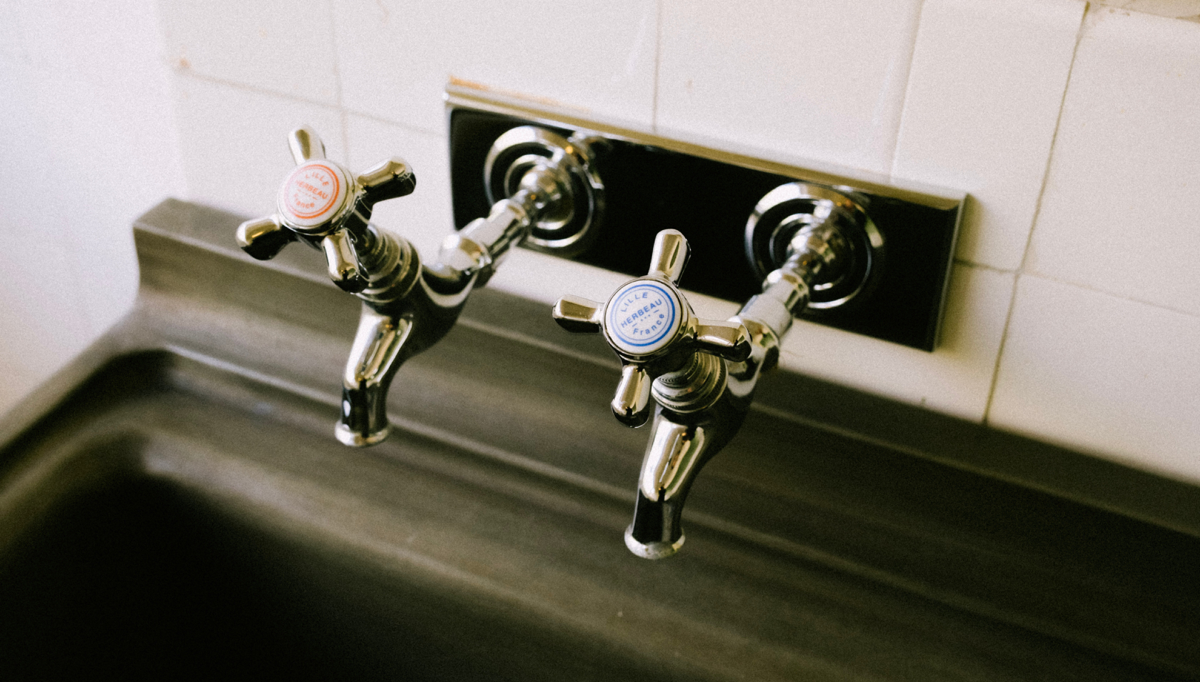
2. Low-Flow Faucets and Showerheads
Low-flow fixtures are often equipped with aerators that mix air with water, creating a mist-like spray. This spray is sufficient for everyday uses like washing hands or dishes and helps conserve more water than a traditional fixture.
Low-flow fixtures can also be equipped with pressure-compensating devices that maintain a consistent flow rate regardless of the incoming water pressure. This ensures that the water used remains consistent even if your home’s water pressure changes.
Choose Low Flow Fixtures to save water
A low-flow faucet or showerhead, for instance, can help you save anywhere from 10-15% in water usage, depending on what type of device you choose.
3. Greywater Systems
Two types of greywater systems are available: point-of-use (POU) and whole-house systems. POU systems use a pump and filter to collect greywater from one or two fixtures, such as a bathroom sink or shower.
Whole-house systems capture all of the greywaters from the house, treating and storing them for future use. Depending on the size of your home and the type of system you choose, installation costs can start from a few hundred dollars up to several thousand.
Overall, greywater systems are an excellent way to help conserve water in your home. They are a cost-effective and efficient way to reduce water usage while helping you save money on utility bills.
When choosing a greywater system, select one certified for safe use, as some systems can be hazardous if not properly maintained. Also, check with your local authorities, as regulations for greywater systems vary by state. If done correctly, a greywater system can be a great way to conserve water in your home!
4. Low-Flow Toilets
Low-flow toilets are one of the most popular plumbing upgrades for conserving water. These toilets are designed to reduce the amount of water used with each flush, using around 1.6 gallons of water in every flush, unlike traditional toilets, which can use up to 3.5 gallons per flush. This makes low-flow toilets a great option for saving on water bills and reducing water waste, and they are usually quite affordable, too.
Choose Low Flow Fixtures to save water
5. Tankless Water Heaters
Modern tankless water heaters have features that will ensure that you’re only heating water when needed, helping save even more water in the long run.
Some models come equipped with features that allow users to set their desired water temperature, which helps ensure that only the necessary amount of water is heated instead of wasting hot water that isn’t being used. Others come with recirculating pumps installed so that hot water reaches your fixtures quicker than usual. This means less water is wasted while waiting for hot water to reach the faucet or shower head.
However, installing a tankless water heater may be challenging. Water heater installation should include proper measurements to ensure the toilet fits comfortably in the available space.
During a water heater installation, professional plumbers can check for any potential plumbing problems that may cause leaks or other plumbing issues down the road. They also check the connections between the tank and bowl of the new dual-flush toilet to ensure everything fits properly and maximizes water conservation.
Save Water and Energy with These Plumbing Upgrades
Making eco-friendly home improvements can greatly lower your water and energy usage, saving you money and helping the environment simultaneously. If you’re looking to reduce your water and energy consumption, plumbing upgrades are one of the best places to start.
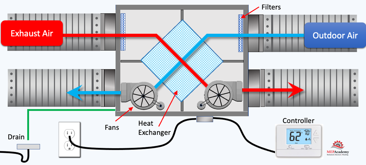
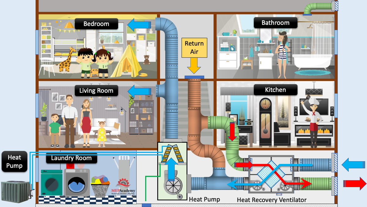
Learn how a Heat Recovery Ventilator works. The purpose of the Heat Recovery Ventilator is to transfer sensible heat between the incoming and exhaust air streams, and to increase indoor air quality. Instead of wasting the heat, it’s recovered from the exhaust stream in cold climates and in warmer climates the incoming hot air is cooled down by giving up some of its heat by the cooler exhaust leaving the building.
Ventilation air is required for human health and indoor air quality. The conditioning of this outdoor air takes lots of energy. By using a heat recovery ventilator, the load on the air conditioner can be reduced, thereby creating a more efficient system.
The heat recovery ventilator is made of a painted galvanized steel housing. There is a supply and exhaust fan capable of multiple speeds. There should be washable and/or disposable filters at the intake to both fans to keep the fans and heat exchanger clean. Some commercial HRV’s allow for final filters, which is a second set of filters of higher quality.
Heat Recovery Ventilator Construction
Then there is the air-to-air heat exchanger which is made of polypropylene or aluminum. There will be a 120-volt power cord that plugs into any nearby outlet or hard wired to a circuit breaker in a nearby electrical panel. A low voltage control wire will be routed from the controller to a connection on the ventilator.
A drain pan and drainpipe will be needed to carry away any water that accumulates during heat transfer or the defrost cycle. There will need to be two holes cut in the exterior wall to allow for the ventilation intake and exhaust grilles. Ductwork will be routed from the grilles to the heat recovery ventilator. The ductwork can be pre-insulated flexible duct or rigid round with insulation.
HRV manufacturers position their fans and filters differently. Some will have the filter before the fan and some after. Some will configure the fans in a blow through arrangement while others use the draw through method.
How a Heat Recovery Ventilator Works
First its best to remember that heat moves from a warmer object to a cooler one as defined by the second law of thermodynamics. Heat will always seek to equalize itself with any cooler objects it meets. Therefore, you wear a jacket in winter, to retain the heat in your body and avoid it from equalizing with the cold outdoor air.
Now we’ll explain three common methods of using a Heat Recovery Ventilator. One method is used without an air conditioner or furnace, the next one with an integrated A/C system, and the final one integrated with all connections on the return duct feeding an air conditioner.
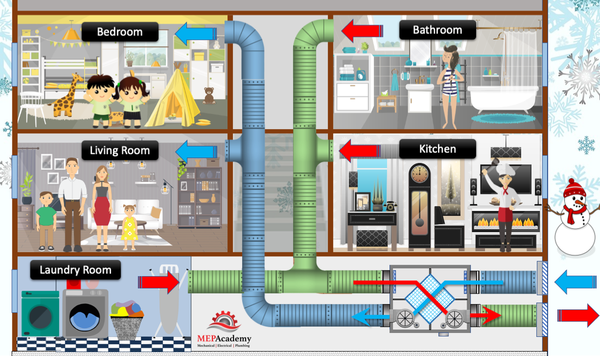
Ventilation air Ductwork will be routed from the outdoors through the heat recovery ventilator to various rooms, like bedrooms, living rooms and family rooms. It’s recommended to design the airflow so that the fresh air is routed from clean spaces to rooms where the air is to be exhausted because of odors. This would have the fresh air travel into the bedroom and then be exhausted through the bathroom, kitchen or laundry room where smells are generated.
Heat Recovery Ventilator without Air Conditioning
This will provide a good path for fresh air to enter spaces where occupants are sleeping and living, while exhausting areas that generate smells or have stale air. This moves fresh air from clean areas through dirty areas. Now let’s add an air conditioning unit to the space.
This will require an outdoor unit and an indoor air handler. See our video on “How Split System Air Conditioners or How Heat Pumps Work” for an explanation of these systems. The indoor and outdoor units are connected with refrigerant piping.
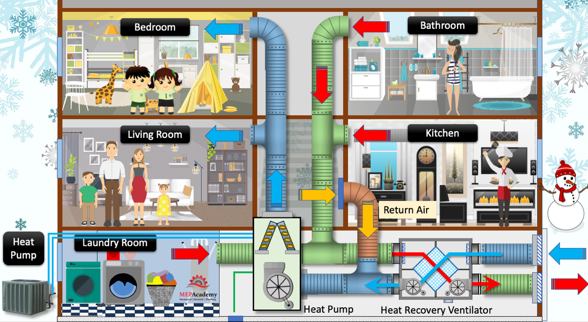
Heat Recovery Ventilator with Heat Pump Unit
The heat recovery ventilator works the same way but is connected directly to the return air duct of the heat pump unit. The fresh air duct will need a manual volume damper to balance the air volume. The fresh air will be distributed through the existing air conditioning or furnace supply air ductwork. This requires that the air conditioner is running any time the heat recovery unit is running. There is an interlock between the two systems to ensure that one is not running without the other.
A backdraft damper should be provided in the return air duct upstream of the fresh air connection. This will avoid the heat recovery ventilator from pushing air backwards through the return air ductwork if the air conditioner was off or failed. Also, the distance from the return air connection to the air conditioner to where the fresh air tap into the return air is dictated by code, check your local code for distance requirements. Some manufacturers require at least 10 feet (3 m)
If the building has more than one air conditioner, there will need to be a separate Heat Recovery Ventilator for each.
Heat Recovery Ventilator integrated with Return Duct of A/C System
The heat recovery ventilator works the same way but once again is connected differently. Both the fresh air intake and exhaust are connected to the return air ductwork. Instead of taking air directly from the bathroom, kitchen or laundry areas, this system arrangement just exchanges enough return air with the required amount of fresh air.
Heat Recovery Ventilator with Return Air Duct
The bathroom and laundry rooms can have their own exhaust fan while the kitchen will have a range hood to exhaust air when cooking on the stove.
How to Size a Heat Recovery Ventilator
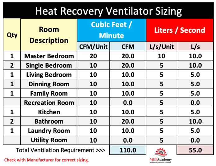
For small residential properties various equipment manufacturers provide convenient charts based on a quantity of cubic feet per minute (CFM) or Liters per Second (L/s) for each room in the home. Bedrooms receive the greatest amount of CFM (L/s), followed by all other rooms. One manufacture recommends 20 CFM (10 L/s) for Master Bedrooms and 10 CFM (5 L/s) for each of the other bedrooms and spaces within the home.
Heat Recovery Ventilator Sizing Chart Based on CFM or Liters/second
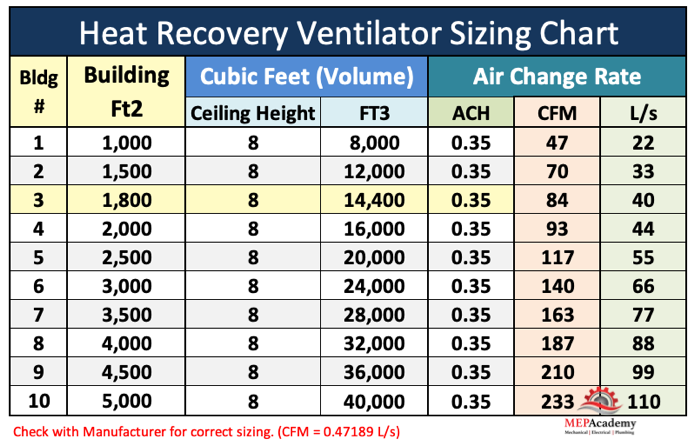
Another sizing method uses Air Changes per Hour (ACH). See our video on Air Changes per Hour for a better explanation. One manufacturer recommends 0.35 ACH. The formula would look like this: Total Ft3 of building x 0.35 ACH / 60 Minutes/Hour.
Example: A 30’ x 60’ home
1,800 Ft2 x 8’ Ceilings = 14,400 Ft3
14,400 Ft3 x 0.35 ACH = 5,040 Ft3
5,040 Ft3 / 60 minutes = 84 CFM (40 L/s)
Heat Recovery Ventilator Sizing Chart
Winter Mode
Cold fresh air is brought into the ventilator through a filter by a blower fan. The blower sends the cold air into the heat exchanger where it absorbs heat from meeting the material of the heat exchanger. The heat exchanger is warmed up by the exhaust air leaving the building. The exhaust air is brought in from the spaces within the building. The exhaust is filtered before the blower and then sent across the heat exchanger, before being thrown outdoors.
A heat recovery ventilator brings in ventilation air through one end and exhaust air through the other end. They cross paths internally within the ventilators heat exchanger, but the air streams never physically mix, so there is no contamination of the fresh air by the stale exhaust air. Instead, they transfer heat between heat exchanger surfaces that keep the two air streams separated.
If frost accumulates then a defrost cycle could be implemented whereby the supply fan shuts off, while the exhaust fan speed increases. This allows the warm exhaust time to defrost the system when no supply air is brought in. The defrost cycle is turned on by measuring the temperature of incoming ventilation air. If the air is too cold the defrost cycle commences for a fixed time.
Summer Mode
The process is the same as in winter except that warm air is now brought in with the ventilation air. The blower sends the warm fresh air into the heat exchanger where it rejects heat as it crosses paths with the cooler exhaust air. The heat exchanger is warmed up by the ventilation air entering the building. The exhaust air is from the bathroom, kitchen and laundry as we showed before. The cooler exhaust air is filtered before the blower sends it across the heat exchanger where it picks up heat, before being exhausted outdoors.
Heat Recovery Ventilator versus an Energy Recovery Ventilator
First, we need to explain that there is a difference between a Heat Recovery Ventilator (HRV) and the Energy Recovery Ventilator (ERV). An Energy recovery ventilator removes both sensible and latent heat (humidity), while a heat recovery ventilator removes only sensible heat. Remember that sensible heat involves raising or lowering the dry bulb temperature of the air and doesn’t include the energy required for water vapor to change state. Latent heat is associated with water vapor and humidity.
Heat Recovery ventilators are cost effective at reclaiming heat during winter and are used in colder climates, while energy recovery ventilators are used in warmer humid climates to help control humidity.
Heat Recovery Ventilator Control
There are various methods for activating the heat recovery ventilator.
Thermostats can turn the unit off and on based on temperature or fan only status. Remember if the ventilator isn’t running, there won’t be any fresh air coming into the building by this method.
If used with Carbon Monoxide Detectors, some manufactures offer an interface connection that would allow the fan to go into high-speed mode. This would assist with CO dilution and exhaust.
These units can also use a humidistat to control the speed of the fan. When humidity levels get too high within the space the humidistat can call for the fan to go into high-speed mode. Humidistats can be in bathrooms, laundry rooms or kitchens where moisture is generated. But remember, this is a heat recovery unit, it does not remove latent heat or moisture.
A remote timer can be used to allow occupants to turn the heat recovery ventilator on for the duration that they plan to occupy the space. There are also programmable fan timers that can be set to allow the system to come on and off throughout the day based on a schedule.
A simple switch could be used to allow occupants to turn the unit on and off as they wish, or the switch can allow for high-speed fan operation.
The recovery ventilator could also be connected to a building management system in a commercial application.
Heat Recovery Ventilator Maintenance
Remember to disconnect the power before performing any maintenance or hire a professional to avoid unintended accidents.
As with any air moving equipment, filters will need to be cleaned or replaced every quarter or based on usage.
Clean the fans of any dust or grease that may have attached itself to the fan blades and fan housing.
Check the drain opening and connected piping to ensure that the pathway is clear for condensate to flow unobstructed.
Inspect the ventilation intake grille to ensure that the opening isn’t clog with debris like leaves and trash.
Have the air ducts inspected and cleaned, if need be, or replaced if in poor conditioned. A dirty or leaking air duct will reduce the performance of the heat recovery ventilator.
Clean the heat exchanger of any dust that may have accumulated. Some units allow for the easy removal of the heat exchanger and allow cleaning with a warm water/detergent solution. Check the manufacturers literature for maintenance and cleaning requirements.
Make sure to maintain all clearance requirements for the removal of the core and fans. The manufacturers literature will indicate the required clearances.
Do not exhaust clothes dryers, flammable fumes, dusty environments, or appliances.
1 CFM = 0.47189 L/s
1 L/s = 3.6 m3/Hr.
The heat recovery ventilator is designed to recover or reject heat in homes, hotels, offices, meeting halls and just about anywhere except where the air contains coarse dust, soot, flammable, or explosive mixtures, or any dangerous or harmful substances.
Digital Planner for Construction Estimators. This is the only digital planner especially made for construction estimators that allows for tracking of all the important task of the job.
The digital planner is automatically linked to all the pages, just click any link and it will take you to that page. This digital planner is available for the GoodNotes and Notability Apps.
Estimating Bid Schedule indicates all current projects bidding
Let’s start with the Bid Schedule. Here is where you will list all the projects that you’re currently bid including the bid due date and time, any job walk and RFI deadline dates and who it bids to. The first item which is the Estimate number is used throughout the planner to track all the documents related to that particular project.
Bid Log
The bid log is a history of all your bids for the current year. Here is where you can quickly go to see the date of any project you bid, the amount of the bid, the corresponding material take off pages which we’ll show shortly.
Keep Track of all your estimates in one neat file according to the year it was bid
The delivery method whether plans and specs or Design/Build or any other method, and whether you were successful. Keeping track of your wins and losses for the year will help you at the end of the year to do a wins/loss percentage and to see what type of jobs you were most successful at.
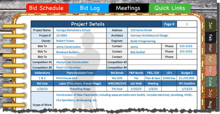
Project Details
Next we’ll hop over to the “Project Details” page where you can quickly see the address of the project and the key players, like owner, Architect, Engineer. Who the competition is. If bid bonds, Performance and Payment bonds are required.
Details of project your bidding. All project details for the year in one simple digital file for safe keeping.
Delivery method, and if Liquidated Damages apply. If there is a owner budgeted amount. If there are any labor requirements, such as prevailing wages, any disadvantaged enterprise participation requirements, bid meetings, and a place to indicate a brief scope of work.
Job Walks
This form keeps track of all your job walks and a list of those in attendance and it records any important details that need to be noted.
Construction Job Walks – Keep Track of Job Walks and Important details
RFI Log
There is an RFI log to track when RFI’s are due and if and when you submitted any with a brief description of the scope.
Request for Information (RFI Log)
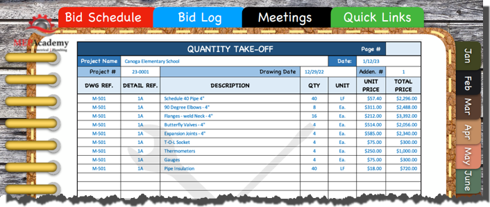
Quantity Takeoffs
You can do material takeoffs if you like and it will remain in your digital planner for ever. Document the drawing and detail number along with a description of the item required. Back at the office input the required material and labor cost for a quick estimate.
Material Takeoffs are easily documented in the digital planner.
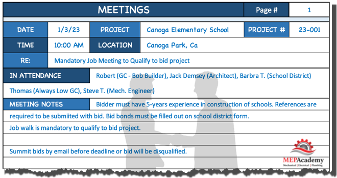
Project Meetings
Keep track of all your project meetings for the year in one neat digital planner. This is a record of when and where meetings are held, and who was in attendance, along with notes of what was discussed and the important items that need your attention.
Estimating Meetings
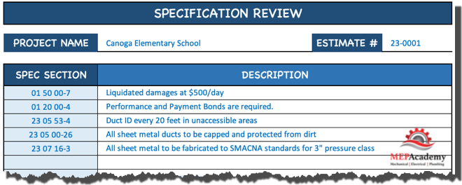
Specification Review
Record all the important sections of the specifications to ensure that you don’t forget to cover the cost of high impact specification sections.
Construction Specification Review Notes
Goals
List your personal and business goals. Remember if you write it down you’re more likely to accomplish your goals. So start tracking your goals.
Misc.
This is for anything you want it to be.
Note Paper
Somewhere to take additional notes for later review. Items that may not fit in any other category.
Things to Do
List the important things that you need to get done every day, starting with this most important to your success in life and business.
Graph Paper
Somewhere for you to make sketches of project conditions or when discussing construction projects with the owner, contractor or sub.
Monthly Calendar
The digital calendar includes all the months for the year.
Yearly Overview
Included is the complete yearly calendar for quick reference.
This digital planner has everything you need to keep accurate records of your complete year of estimating, all in one easy file.
Any of the pages can quickly be duplicated, allowing for an endless amount of projects and estimates for the year.
Start keeping track of all your estimates by requiring a digital planner of all your estimators.
How do Geothermal Heat Pumps work? We’ll learn the different types of Geothermal Heat Pump Systems, along with information on where to find incentives and rebates, the efficiency compared to a regular heat pump and the cost you might expect to pay to have one installed.
If you prefer to watch the video version of this presentation than scroll to the bottom or click the link here “How do Geothermal Heat Pumps work?“
Ground Source Heat Pumps – Ground Temperatures and Loop Depth
The use of geothermal heat pump systems takes advantage of the earths relatively constant temperature beneath the surface based on location and height. The earth maintains a ground temperature range from 45°F (7°C) to 75°F (21°C). taking advantage of this natural heat source is what gives the Geothermal Heat Pump greater efficiencies than a standard heat pump. This source of heat is also naturally renewable making it a great energy source.
The Geothermal Heat Pump System comes with various options on how to tap into this natural reservoir of heat. We will discuss open and closed loop systems, and horizontal versus vertical system, and when to use them.
The cost of a geothermal heat pump system is more than that of a typical heat pump system, but this cost is saved by possible incentives and rebates in addition to the yearly energy savings which we’ll cover shortly.
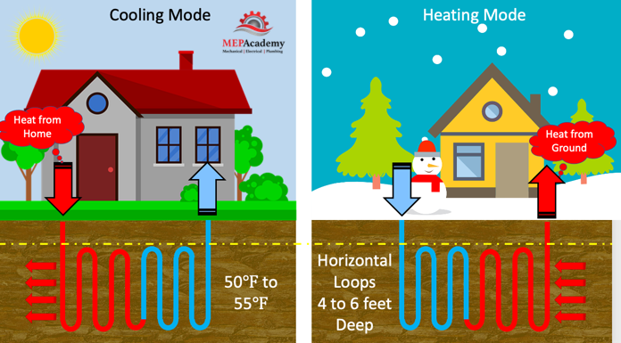
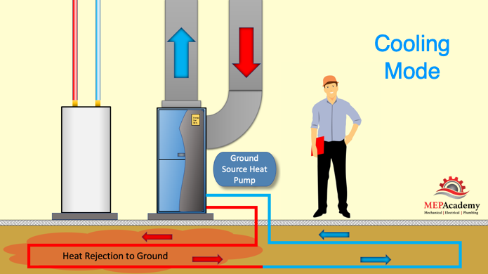
In cooling mode, warm air from within the building is brought into the ground source heat pump. The heat pumps indoor coil will absorb the warm air into the cooler liquid refrigerant circulating through the coil. Absorbing the heat will cause the refrigerant to boil and turn into a gas. The refrigerant will circulate through the system and be absorbed by the cooler water circulating through the system from the underground.
The heat is then absorbed by the water and circulated underground where the heat is rejected to the cooler ground. Remember the 2nd law of thermodynamics states that heat moves from a warmer to a cooler item. The water and refrigerant never come in contact with each other. For a complete understanding of the refrigerant cycle see our other video.
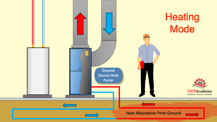
Geothermal Heat Pump System in Heating mode
Geothermal Heat Pump in Heating mode
In heating mode the opposite occurs. We will always follow the heat as stated by the second law of thermodynamics. The heat in this case is provided by the ground. The cool water is circulated to the ground where it absorbs heat from the ground.
This warm water then circulates into the ground source heat pump where it is absorbed into the refrigerant causing the liquid refrigerant to boil and turn into a vapor. The hot refrigerant is then circulated to the indoor coil where it comes in contact with the cooler return air from the space. The cool return air absorbs the heat from the hot refrigerant and heats the leaving supply air.
In order to tap into the earths free source of energy we’ll need to run plastic tubing beneath the surface. This tubing acts as a heat exchanger between the fluid in the tubes and the ground. The tubing is configured in various patterns and depths based on available land area and the composition of the soil below ground.
If there is enough ground area and the soil is good for heat transfer than a horizontal system can be installed. If there isn’t enough ground area or the soil isn’t good for heat transfer, then vertical tubing is another option. These systems circulate water with antifreeze or there is the option to use a refrigerant based system. Another option if you have a body of water nearby is to use an open or closed loop system into the body of water. We’ll cover each of these now.
Horizontal loop GSHP
Given enough area for the tubing to achieve the heat transfer required to support the cooling and heating load of the building or home, using the horizontal loop is more feasible than drilling vertically. Horizontal loops are buried from 3 to 5 feet (0.9 to 1.5m) deep and are economically feasible as long as excavation can be done without difficulty due to soil composition.
Geothermal Heat Pump Horizontal Trench with Looped Tubing
The length of the loop is determined by the amount of heat transferred required or the tonnage of the heat pump. In order to determine the length of tubing required, a heating and cooling load calculation is performed on the building. Tube length can run between 500 to 600 feet (152 to 182m) per ton of heat pump capacity. This means that a 4-ton system would require 2,000 to 2,400 feet (610 to 732m) of tubing. Allowing for spacing to achieve efficient heat transfer, an approximate area from 1/4 to 3/4 acre could be required for a typical sized home.
Vertical Loop GSHP
Using vertical loops requires less land area as the tubing is sent hundreds of feet below the surface. For commercial buildings this could include bore holes 100 to 500 feet (30 to 152m) deep, spaced 20 feet (6m) apart to allow for proper heat transfer. These holes can be up to 4” to 6” (10 to 15cm) in diameter and contain plastic tubing that traverses to the bottom where it makes a U-turn and comes back out of the hole where it connects to a horizontal manifold. Residential systems would require fewer bores and would most likely be 300 feet (91m) deep or less. Vertical loops can be used when there isn’t enough land area and when greater efficiency maybe required.
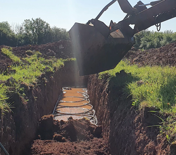
The Slinky Geothermal Loop Installation
This geothermal System uses coiled tubing which allows for the use of less area by increasing the heat transfer ability per area used. This occurs because the tubing is coiled in the trench requiring less land area, but more tubing per linear feet. The coils are laid in a horizontal trench 3 to 8 feet (1 to 2.4M) deep. A combination of water and antifreeze circulate through the tubing and the heat pumps heat exchanger.
Geothermal Heat Pump Loop
DX Refrigerant Based Geothermal Ground Loop
Another energy efficient option is the DX ground loop system that uses refrigerant circulating around a buried copper coil. Instead of water, refrigerant is the heat transfer medium, avoiding the additional step of transferring the heat to the refrigerant in a water based system. This helps with the increased efficiency and greater heating capacities. This also eliminates the need for a water pump, as this is a waterless system.
Another difference is that this loop is in a wide vertical hole, something like 3 feet (1m) in diameter and 70 feet (21m) deep. This eliminates the need for large areas of land. The soil will need to be tested to make sure it’s not corrosive to the copper, and if found to be corrosive then a ground loop protection method will be installed.
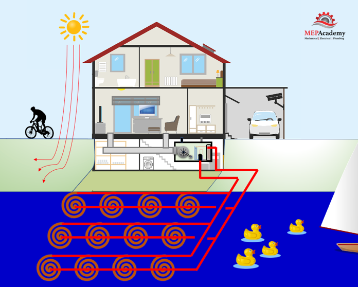
Having a body of water near the property allows for the option of using water as the heat sink, where heat is transferred to and from the tubing either in an open or closed loop arrangement.
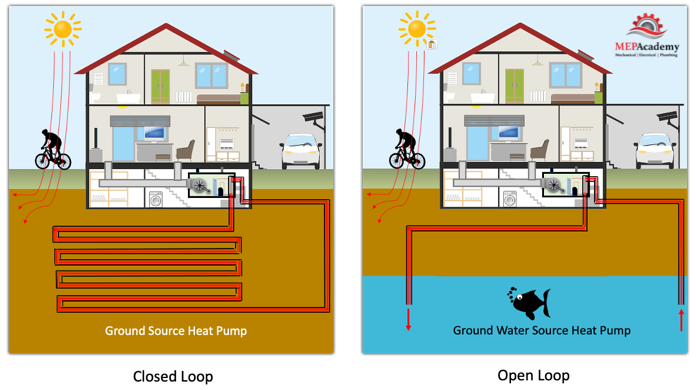
Ground Source Heat Pump – Closed and Open Loop Systems
Closed loop Systems.
The tubing can be installed at the bottom of a pond on the property if the pond is large enough, maybe 1/2 an acre or larger depending on its depth. If close enough to a lake this option is also available pending local authority approval. A pump circulates the water and antifreeze solution through tubing within the body of water where it rejects or absorbs heat from the geothermal heat pump.
The use of lakes, wells, ponds or waterways for a heat sink.
Open Loop System
The difference between the closed and open loop systems is that the open system uses the pond, well or lake water to be circulated through the tubing and up to the heat pump. This raises additional concerns for environmentalist and code authorities about water depletion and ground water contamination.
The use of well water is an option if a body of water exist under your property and the use of a horizontal ground loop doesn’t work for lack of area or feasibility. Open loop systems require more maintenance than a closed loop, due to the minerals and other impurities that maybe in the water.
Are open loop Systems Legal?
There are laws governing the use of bodies of water for the use of any open system that will take water from the source and use it in some process before returning it back again. The legitimate concern is what happens to the quality of the water in the process. Another concern is for the wild life or living organism in the water that maybe effected by the warmer discharge temperatures.
You’ll need to check with the jurisdictional authority when contemplating the use of any body of water. An alternative would be a closed loop system which should be less stringent.
Is a Geothermal Heat Pump System worth the Cost?
Energy savings from the installation of a geothermal heat pump system could take anywhere from 5 to 10 years to payback the additional investment cost above a conventional system according to the department of energy.
The DOE states that an average geothermal heat pump system costs about $2,500 per ton of capacity. If a home requires a 3-ton unit, then it would cost about $7,500 (plus installation and drilling costs). A comparable Air Source Heat Pump system with air conditioning would cost about $4,000, but the energy costs could easily equate to the extra cost of installing a geothermal heat pump.
Geothermal heat pump systems have an average 20+ year life expectancy for the heat pump itself and 25 to 50 years for the underground infrastructure.
Geothermal Heat Pump System Frequently Asked Questions (FAQ)
1) How Long Do Geothermal Loops Last?
The geothermal loop is buried underground so it’s protected well and should last anywhere from 50 to 100 years. The underground piping often has a warranty period of 25 to 50 years, check with the manufacture about their warranty period.
2) How long does it take for a Geothermal System to Pay For Itself?
Based on the type and size of the project the payback period varies but expect 4 years or more. Ask your contractor for a payback analysis.
3) Do Geothermal Systems use a lot of Energy?
No. Geothermal systems are used for the purpose of saving energy and providing a more sustainable solution. The heat pump uses electricity but more efficiently.
4) Do Geothermal System Require A lot of Maintenance?
No. Geothermal systems require less maintenance than other types of heat pumps.
5) How Deep Should Geothermal Horizontal Loops be?
Anywhere from 3 to 8 feet (1 to 2.4m) deep is a common depth for a horizontal geothermal heat pump system. The tubing can be placed side by side in a couple feet wide trench, or spaced several feet apart at different depths in a more shallow trench.
6) What is better, a Closed or open loop Geothermal System?
A open loop system will be more efficient and less costly, but will be more regulated due to the system discharging into the water way.
7) Can I Install my Own Geothermal System?
The installation is best done by an experienced contractor and is not something a home owner should attempt on their own.
8) Do you need supplemental Heat when using a Geothermal Heat Pump?
A properly sized Geothermal heat Pump should be sufficient to handle the calculated heating and cooling load of a space. This is why it’s important that a load calculation be done to ensure that the system is sized correctly. If need be, additional electric heat can come on after its maxed its capacity
9) Is a Geothermal System worth the investment cost?
One of the greatest benefits of a geothermal system is that they use 25 % to 50% less electricity than your typical heating and cooling system. And efficiencies can be increased by adding a desuperheater that heats the domestic water. If you consider the environment then the investment value is increased as less carbon is injected into the environment.
10) What material is used for geothermal heat pump underground tubing?
The three most commonly used materials for water based systems include PEX (polyethylene), HDPE (high-density polyethylene) and PE-RT (polyethylene (PE) resin).
11) Can my Geothermal Heat Pump be powered by a Solar System?
A PV Solar system can provide the power needed to run a geothermal heat pump. Have your contractor do a comparative analysis between the capacity of the solar system and the required power of the heat pump system.
12) How much does a Geothermal System Cost?
Cost vary by location and type of system installed. Residential systems can range from $25,000 on the low end for a small system to over $60,000 for larger systems. For commercial properties the range is much greater because the system sizes encountered are much larger than residential systems.
13) What size tubing is used for Geothermal Heat Pump Systems?
The loops are typically using 3/4” to 1” (1.9 to 2.54cm) tubing, while the main headers will be larger in the range of 1-1/2” (3.8cm) for a 3-ton system.
14) Are there any Tax Rebates or Incentives for Geothermal Heat Pump Systems?
In 2022 tax credits were extended through 2034 for ENERGY STAR rated geothermal systems. Check local utility companies for incentives and geothermal Heat Pump manufactures for rebates.
Geothermal Heat Pump Process
One of the first things when considering the installation of a geothermal heat Pump system is to engage an experienced contractor. The contractor should develop a plan for the execution of the system starting with the options on the type of Geothermal System appropriate for your site. This should include a site visit from the contractor and a review of the home or space. A heating and cooling load will need to be done on the home to determine the correct size of the system.
Included in the contractors review should be an analysis of the energy savings from the various heat pump systems, including any possible rebates, incentives or tax credits.